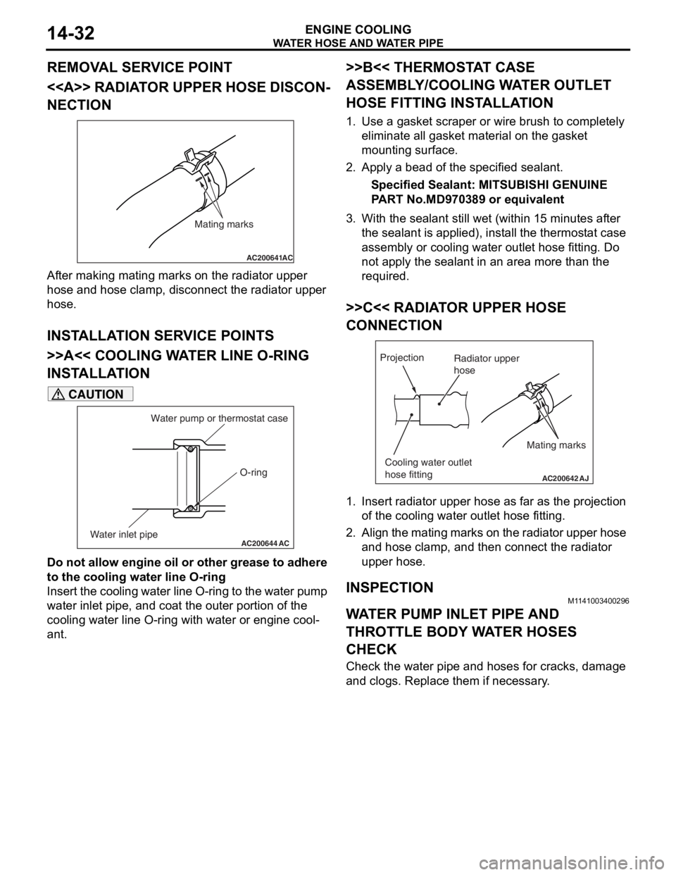
engine MITSUBISHI LANCER 2006 Owner's Guide
[x] Cancel search | Manufacturer: MITSUBISHI, Model Year: 2006, Model line: LANCER, Model: MITSUBISHI LANCER 2006Pages: 800, PDF Size: 45.03 MB
Page 38 of 800
THERMOSTAT
ENGINE COOLING14-24
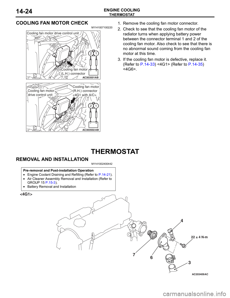
COOLING FAN MOTOR CHECK
M1141007100220
1
2
AC303501AB
Cooling fan motor drive control unit
Cooling fan motor
(L.H.) connector
1
2
AC303502AB
Cooling fan motor
drive control unit
Cooling fan motor
(R.H.) connector
<4G1 with A/C>
1. Remove the cooling fa n mot o r co nnector .
2.Check t o see that t he co oling fan motor of the
ra diato r turns wh en ap plying b a ttery power
b e tween th e con nect o r terminal 1 and 2 of t he
cooling fa n mo tor . Also ch eck to see tha t there is
n o abno rmal soun d co min g from the cooling fa n
motor a t this time.
3.If the cooling fan moto r is defective, replace it.
(Refe r to
P.14-33) <4G1> (Refer to P.14-35)
<4G6>.
THERMOSTA T
REMOVA L AND INST ALLA TION
M1141 0024 0044 2
Pre-removal and Post-installation Operation
•Engine Coolant Draining and Refilling (Refer to P.14-21).
•Air Cleaner Assembly Removal and Installation (Refer to
GROUP 15
P.15-3).
•Battery Removal and Installation
AC203409AC
4
3
6
7
22 ± 4 N·m
<4G1>
Page 39 of 800
AC301429
1
2 36
7
13 ± 2 N·m
AD
5
<4G6>
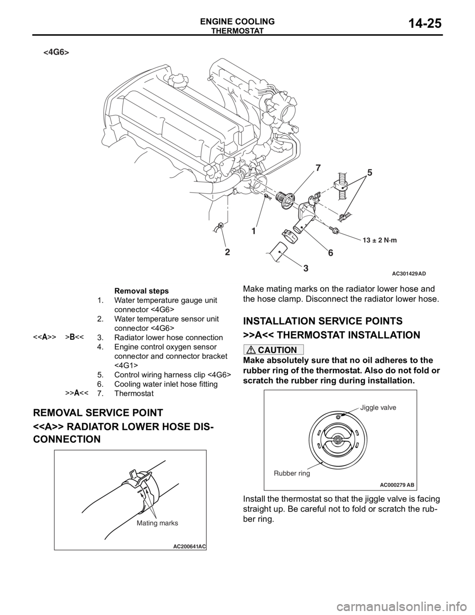
Removal steps
1.Water temperature gauge unit
connector <4G6>
2.Water temperature sensor unit
connector <4G6>
<>>B<<3.Radiator lower hose connection
4.Engine control oxygen sensor
connector and connector bracket
<4G1>
5.Control wiring harness clip <4G6>
6.Cooling water inlet hose fitting
>>A<<7.Thermostat
THERMOST
A T
ENGINE COOLING14-25
REMOV A L SER V ICE POINT
<> RADIAT OR LOW E R HOSE DIS-
CONNECTION
AC200641AC
Mating marks
Make mating marks on the rad i ator lower ho se an d
the hose clamp. Disconn
ect t he radiator lower hose.
INSTALLA T ION SER VICE POINTS
>>A<< THERMOSTA T INST ALLA TION
CAUTION
Make absolutely sure that no oil adheres to the
rubber ring of the thermostat. Also do not fold or
scratch the rubber ring during installation.
AC000279
Jiggle valve
Rubber ring
AB
Install the thermostat so that the jiggle valve is facing
straight up. Be careful not to fold or scratch the rub
-
ber ring.
Page 40 of 800
THERMOSTAT
ENGINE COOLING14-26
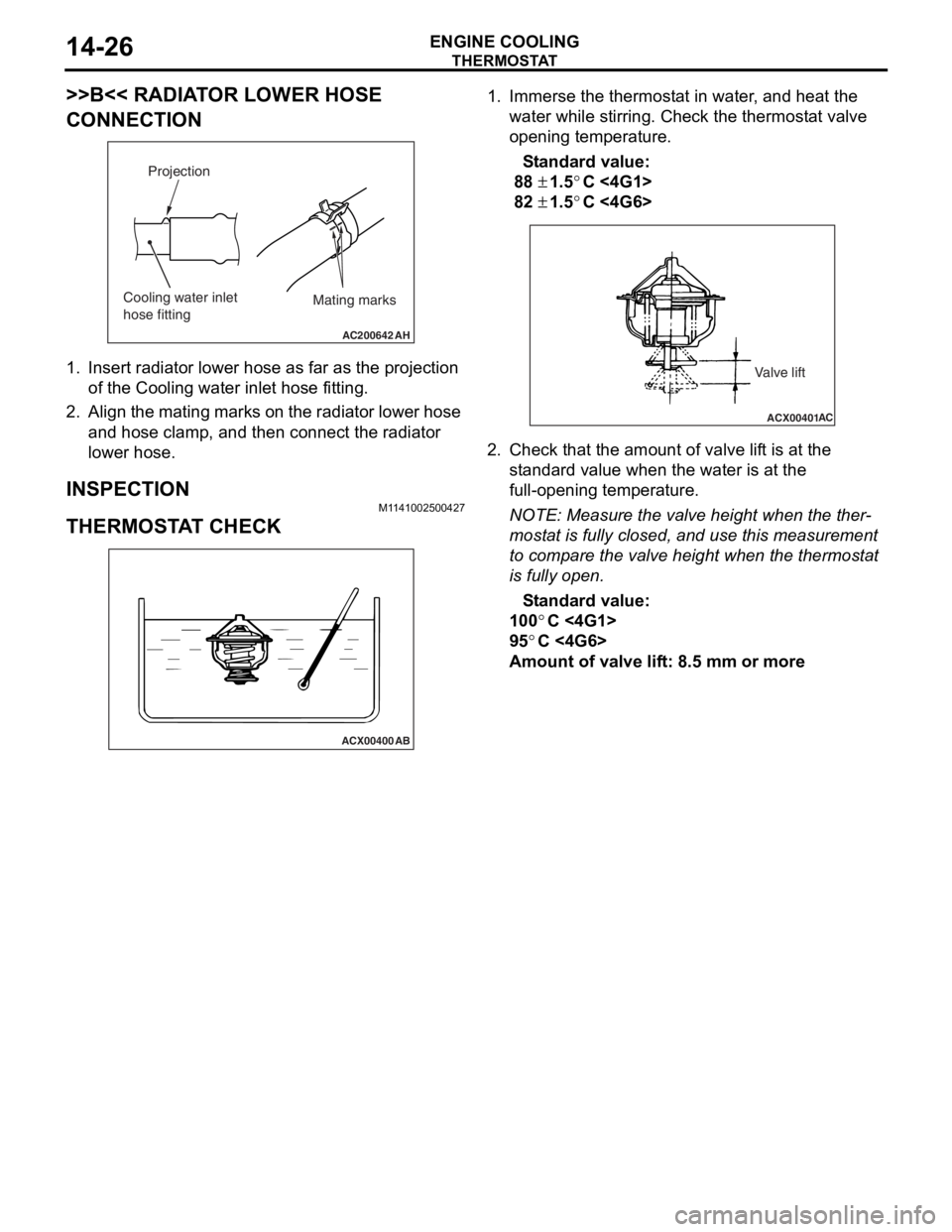
>>B<< RADIATOR LOWER HOSE
CONNECTION
AC200642
Mating marks
Projection
Cooling water inlet
hose fitting
AH
1.In sert ra diato r lower h o se a s fa r as th e projection
of the Cooling wa ter inlet ho se fitting .
2.Align the mating marks on the radiator lower hose
an d hose clamp, and then connect the radia t or
lower hose.
INSPECTION
M1 141 0025 0042 7
THERMOSTA T CHECK
ACX00400
AB
1.Imme rse th e thermost at in water , and h eat the
wate r wh ile stirring. Ch eck the th ermost a t va lve
o penin g temperatu r e.
St andard va lue:
88 ± 1.5°C <4G1 >
82 ± 1.5°C <4G6 >
ACX00401 AC
Valve lift
2.
Check t hat the amo unt of valve lif t is at the
st a ndard valu e when th e water is at the
fu ll-o penin g temperatu r e.
NOTE: Meas ure the valve height when the the r-
mostat is fu lly closed , and use t h is measurement
to
comp are the valve h e ight wh en the thermost at
is fully open.
St andard va lue:
100°C <4G1>
95°C <4G6>
Amou nt of val ve lif t: 8 . 5 mm or more
Page 41 of 800
WATE R P U M P
ENGINE COOLING14-27
WAT E R P U M P
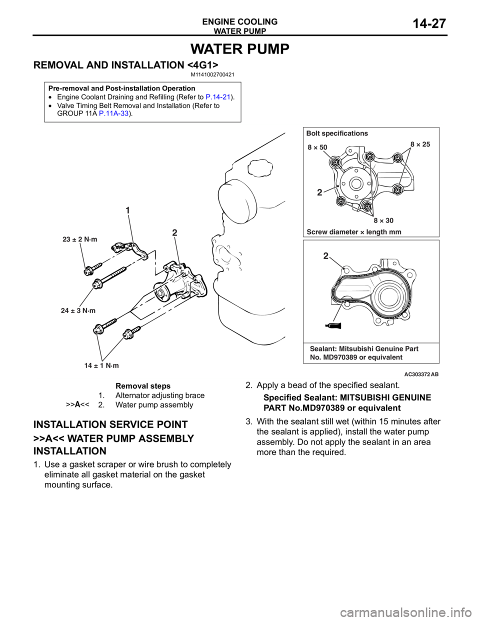
REMOVAL AND INSTALLATION <4G1>M1141002700421
Pre-removal and Post-installation Operation
•Engine Coolant Draining and Refilling (Refer to P.14-21).
•Valve Timing Belt Removal and Installation (Refer to
GROUP 11A P.11A-33).
AC303372
24 ± 3 N·m23 ± 2 N·m
14 ± 1 N·m
1 2
Bolt specifications
Screw diameter × length mm 8 × 50
8 × 308 × 25
AB
2
2
Sealant: Mitsubishi Genuine Part
No. MD970389 or equivalent
Removal steps
1.Alternator adjusting brace
>>A<<2.Water pump assembly
INST ALLA T ION SER VICE POINT
>>A<< WA TER PUMP ASSEMBL Y
INST
ALLA TION
1.Use a gaske t scraper o r wire brush to complet e ly
eliminate all gasket material o n the g a sket
mounting surface.
2. App l y a bead of the specified sealan t.
Specified Sealant: MITSUBISHI GENUINE
P
ART No.MD970 389 or eq uivalen t
3.With the sea l ant still wet (within 1 5 minutes af ter
th e se alant is applied), inst all the wa ter pump
a sse mbly . Do not a pply the sealant in an are a
more th an the required.
Page 42 of 800
WATE R P U M P
ENGINE COOLING14-28
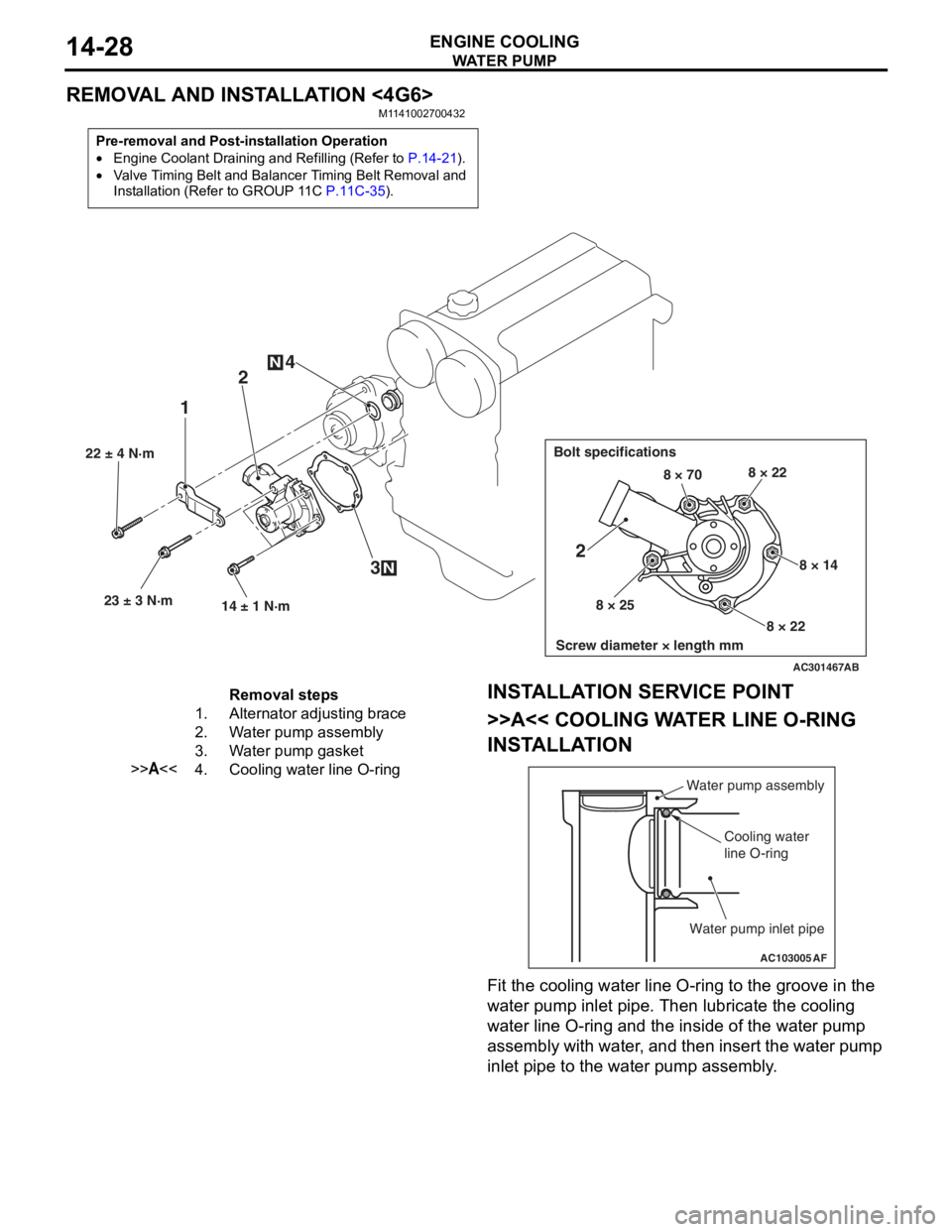
REMOVAL AND INSTALLATION <4G6>
M1141002700432
Pre-removal and Post-installation Operation
•Engine Coolant Draining and Refilling (Refer to P.14-21).
•Valve Timing Belt and Balancer Timing Belt Removal and
Installation (Refer to GROUP 11C
P.11C-35).
AC301467
22 ± 4 N·m23 ± 3 N·m 14 ± 1 N·m
12
3
4
N
N
Bolt specifications
Screw diameter × length mm
8 × 70 8 × 22
8 × 14
8 × 22
8 × 25
2
AB
Removal steps
1.Alternator adjusting brace
2.Water pump assembly
3.Water pump gasket
>>A<<4.Cooling water line O-ring
INST
ALLA T ION SER VICE POINT
>>A<< COOLING WA TER LINE O-RING
INST
ALLA TION
AC103005
Water pump assembly
Cooling water
line O-ring
Water pump inlet pipe
AF
Fit the coo ling water line O-ring to the groove in the
wa
ter pump in let p i pe. T hen lubricate th e co olin g
wa
ter line O-ring and the inside of the wat e r pump
assembly with wa
ter , and then insert the wa ter pu mp
inle
t pip e to the water pu mp asse mbly .
Page 43 of 800
WATER HOSE AND WATER PIPE
ENGINE COOLING14-29
WATER HOSE AND WATER PIPE
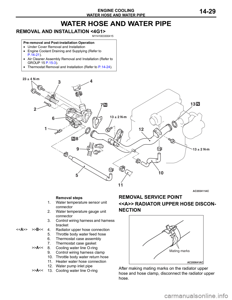
REMOVAL AND INSTALLATION <4G1>M1141003300415
Pre-removal and Post-installation Operation
•Under Cover Removal and Installation
•Engine Coolant Draining and Supplying (Refer to P.14-21).
•Air Cleaner Assembly Removal and Installation (Refer to
GROUP 15 P.15-3).
•Thermostat Removal and Installation (Refer to P.14-24).
AC203411
1
2 3
4
5
6
7
8
10
9
13 ± 2 N·m
23 ± 4 N·m
13 ± 2 N·m
N
N
AC
1112
13
N
Removal steps
1.Water temperature sensor unit
connector
2.Water temperature gauge unit
connector
3.Control wiring harness and harness
bracket
<>>>B<<4.Radiator upper hose connection
5.Throttle body water feed hose
6.Thermostat case assembly
7.Thermostat case gasket
>>A<<8.Cooling water line O-ring
9.Control wiring harness clamp
10.Throttle body water return hose
11 .Heater water hose connection
12.Water pump inlet pipe
>>A<<13.Cooling water line O-ring
REMOV
A L SER VICE POINT
<> RADIAT OR UPPER HOSE DISCON-
NECTION
AC200641AC
Mating marks
After making matin g ma rks on the radia t or upp er
hose
and h o se clamp, disconnect the radia t or upp er
hose
.
Page 44 of 800
WATER HOSE AND WATER PIPE
ENGINE COOLING14-30
INSTALLATION SERVICE POINTS
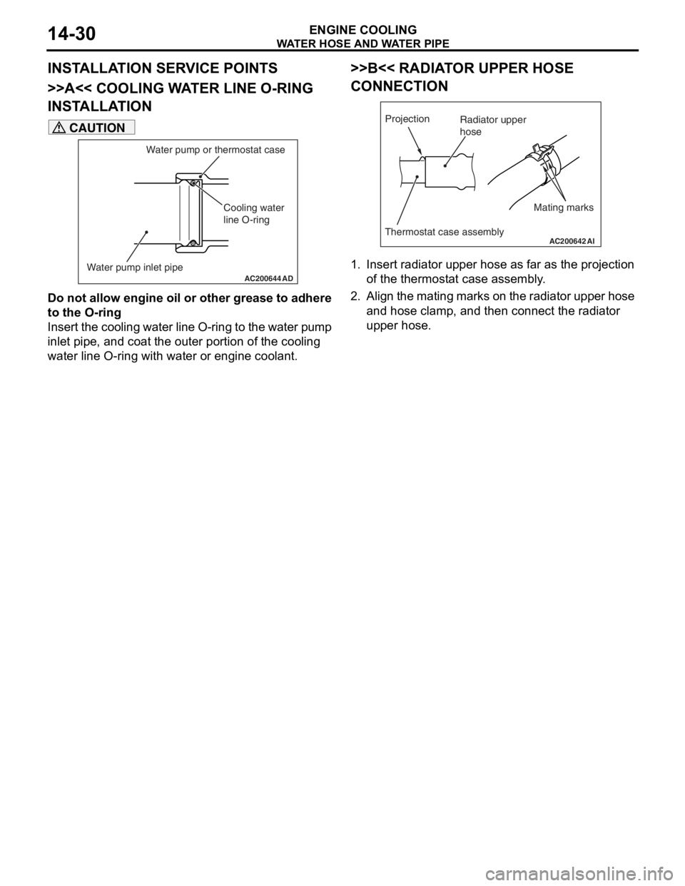
>>A<< COOLING WATER LINE O-RING
INSTALLATION
AC200644 AD
Cooling water
line O-ring
Water pump inlet pipe Water pump or thermostat case
CAUTION
Do not allow engine oil or other grease to adhere
to the O-ring
Insert the cooling water line O-ring to the water pump
inlet pipe, and coat the outer portion of the cooling
water line O-ring with water or engine coolant.
>>B<< RADIATOR UPPER HOSE
CONNECTION
AC200642
Mating marks
Projection
Thermostat case assemblyAI
Radiator upper
hose
1. Insert radiator upper hose as far as the projection
of the thermostat case assembly.
2. Align the mating marks on the radiator upper hose and hose clamp, and then connect the radiator
upper hose.
Page 45 of 800
WATER HOSE AND WATER PIPE
ENGINE COOLING14-31
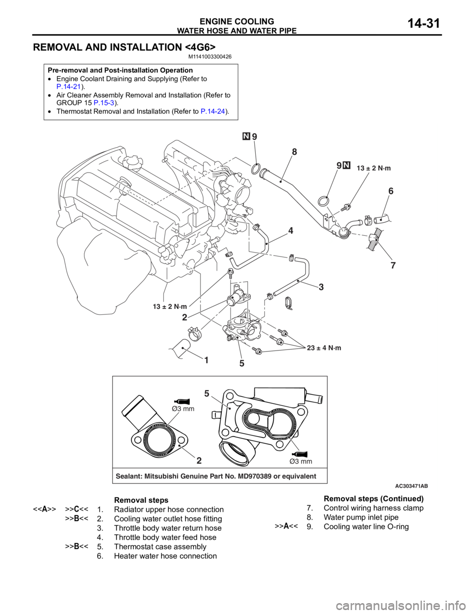
REMOVAL AND INSTALLATION <4G6>
M1141003300426
Pre-removal and Post-installation Operation
•Engine Coolant Draining and Supplying (Refer to P.14-21).
•Air Cleaner Assembly Removal and Installation (Refer to
GROUP 15 P.15-3).
•Thermostat Removal and Installation (Refer to P.14-24).
AC303471
1
2
3
4
5 6
7
8
9
9
13 ± 2 N·m
23 ± 4 N·m
13 ± 2 N·m
N
N
AB
2
Sealant: Mitsubishi Genuine Part No. MD970389 or equivalent
Ø3 mm
Ø3 mm
5
Removal steps
<>>>C<<1.Radiator upper hose connection
>>B<<2.Cooling water outlet hose fitting
3.Throttle body water return hose
4.Throttle body water feed hose
>>B<<5.Thermostat case assembly
6.Heater water hose connection
7.Control wiring harness clamp
8.Water pump inlet pipe
>>A<<9.Cooling water line O-ring
Removal steps (Continued)
Page 46 of 800
Page 47 of 800
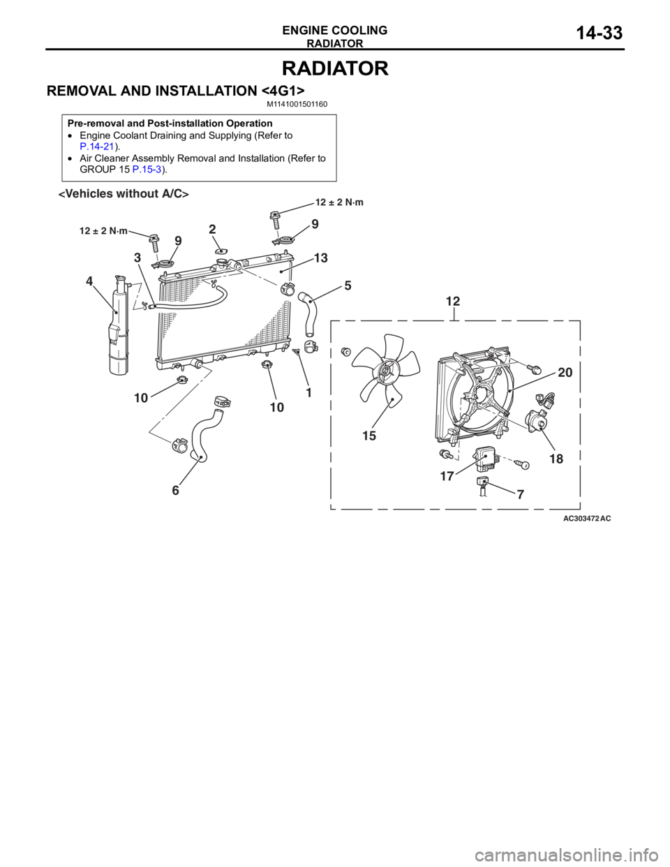
RADIATOR
ENGINE COOLING14-33
RADIATOR
REMOVAL AND INSTALLATION <4G1>M1141001501160
Pre-removal and Post-installation Operation
•Engine Coolant Draining and Supplying (Refer to
P.14-21).
•Air Cleaner Assembly Removal and Installation (Refer to
GROUP 15
P.15-3).
AC303472
18
17
15 20
12
9
13 5
2
9
3
4
1
10
6
10
AC
12 ± 2 N·m
12 ± 2 N·m
7