engine MITSUBISHI LANCER 2006 Repair Manual
[x] Cancel search | Manufacturer: MITSUBISHI, Model Year: 2006, Model line: LANCER, Model: MITSUBISHI LANCER 2006Pages: 800, PDF Size: 45.03 MB
Page 71 of 800
CHARGING SYSTEM
ENGINE ELECTRICAL16-9
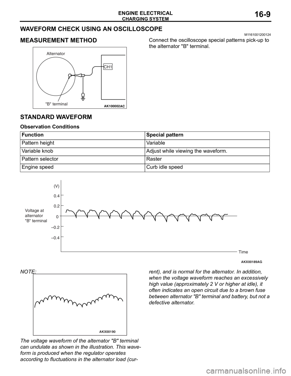
WAVEFORM CHECK USING AN OSCILLOSCOPE
M1161001200124
MEASUREMENT METHOD
AK100002
Alternator
"B" terminal CH1
AC
Co
nnect the oscillo scope specia l p a tt erns p i ck-up to
the alternato
r "B" terminal.
STANDARD W A VEFORM
Observ ation Conditi ons
FunctionSpecial pattern
Pattern heightVariable
Variable knobAdjust while viewing the waveform.
Pattern selectorRaster
Engine speedCurb idle speed
AKX00189
0.4 (V)
0.2
0
–0.2
–0.4
Voltage at
alternator
"B" terminal
Time
AG
NOTE:
AKX00190
The volt age waveform of th e alte rnator "B" t e rminal
can u
ndulate as sho w n in th e illustratio n . This wave
-
form is produce d when t he regu lator operate s
accordin
g to fluctu ation s in the alterna t or loa d (cu r
-
rent), and is normal fo r the alterna t or . In ad dition,
wh
en the volt ag e wavef o rm re ache s an excessively
high
value (app roximate ly 2 V or higher at idle ), it
of
ten indicates an o pen circuit du e to a brown fuse
be
twe e n a l te rn at or "B " t e r m in al an d ba tt er y , b u t n o t a
defective alte
rnator .
Page 72 of 800
CHARGING SYSTEM
ENGINE ELECTRICAL16-10
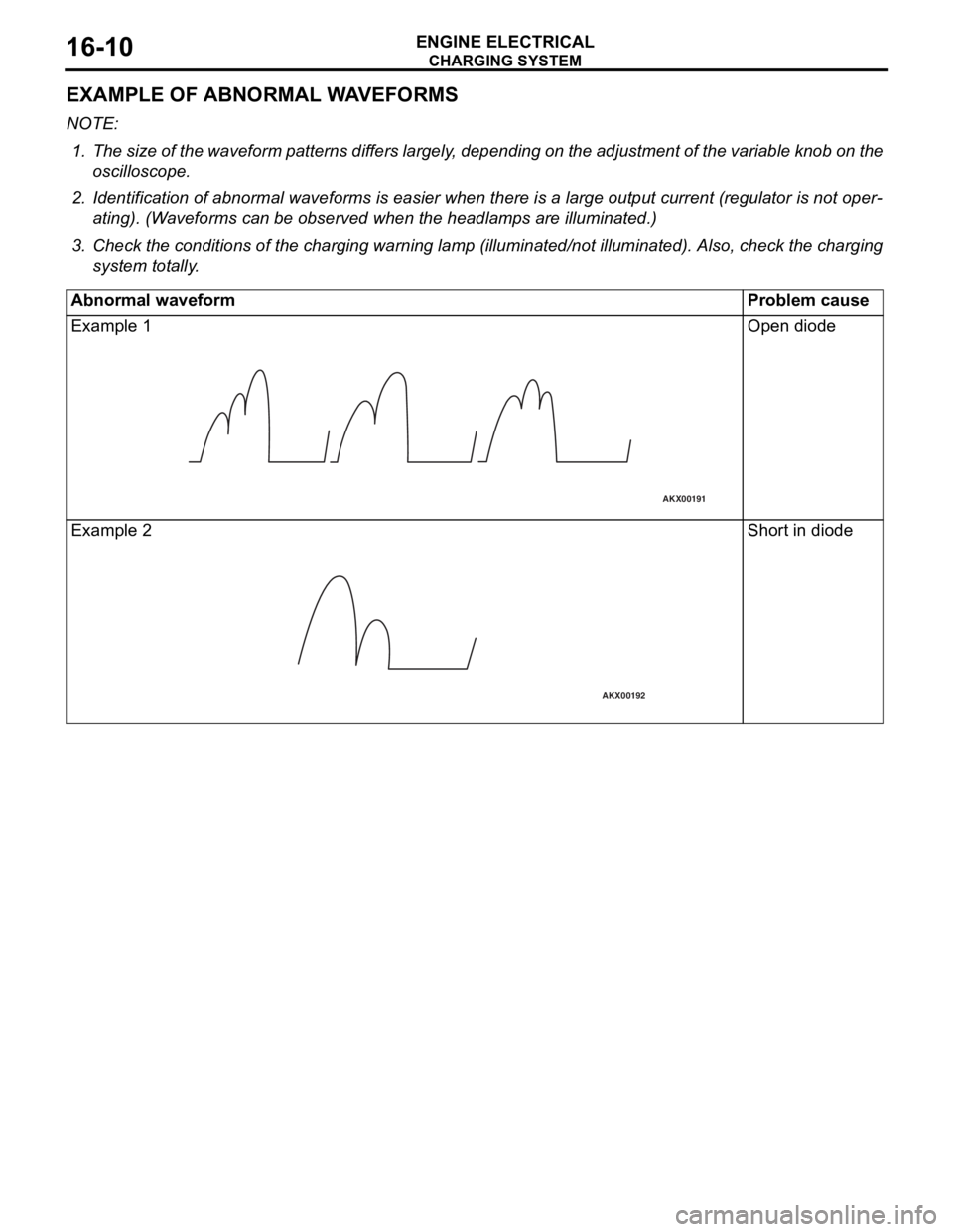
EXAMPLE OF ABNORMAL WAVEFORMS
NOTE: .
1. The size of the waveform patterns differs largely, depending on the adjustment of the variable knob on the
oscilloscope.
2. Identification of abnormal waveforms is easier when th ere is a large output current (regulator is not oper-
ating). (Waveforms can be observed when the headlamps are illuminated.)
3. Check the conditions of the charging warning lamp (illuminated/not illum inated). Also, check the charging
system totally.
Abnormal waveformProblem cause
Example 1
AKX00191
Open diod e
Exampl e 2
AKX00192
Shor t in diode
Page 73 of 800
CHARGING SYSTEM
ENGINE ELECTRICAL16-11
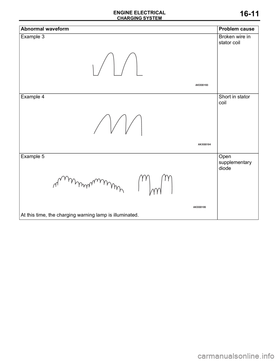
Example 3
AKX00193
Broken wire in
stator coil
Examp l e 4
AKX00194
Shor t in st ator
coil
Exampl e 5
AKX00195
At this time, the charg i ng warn ing lamp is illuminated .
Open
suppleme
n t a ry
d
i ode
Abn o rm al waveform P roble m caus e
Page 74 of 800
CHARGING SYSTEM
ENGINE ELECTRICAL16-12
ALTERNATOR ASSEMBLY
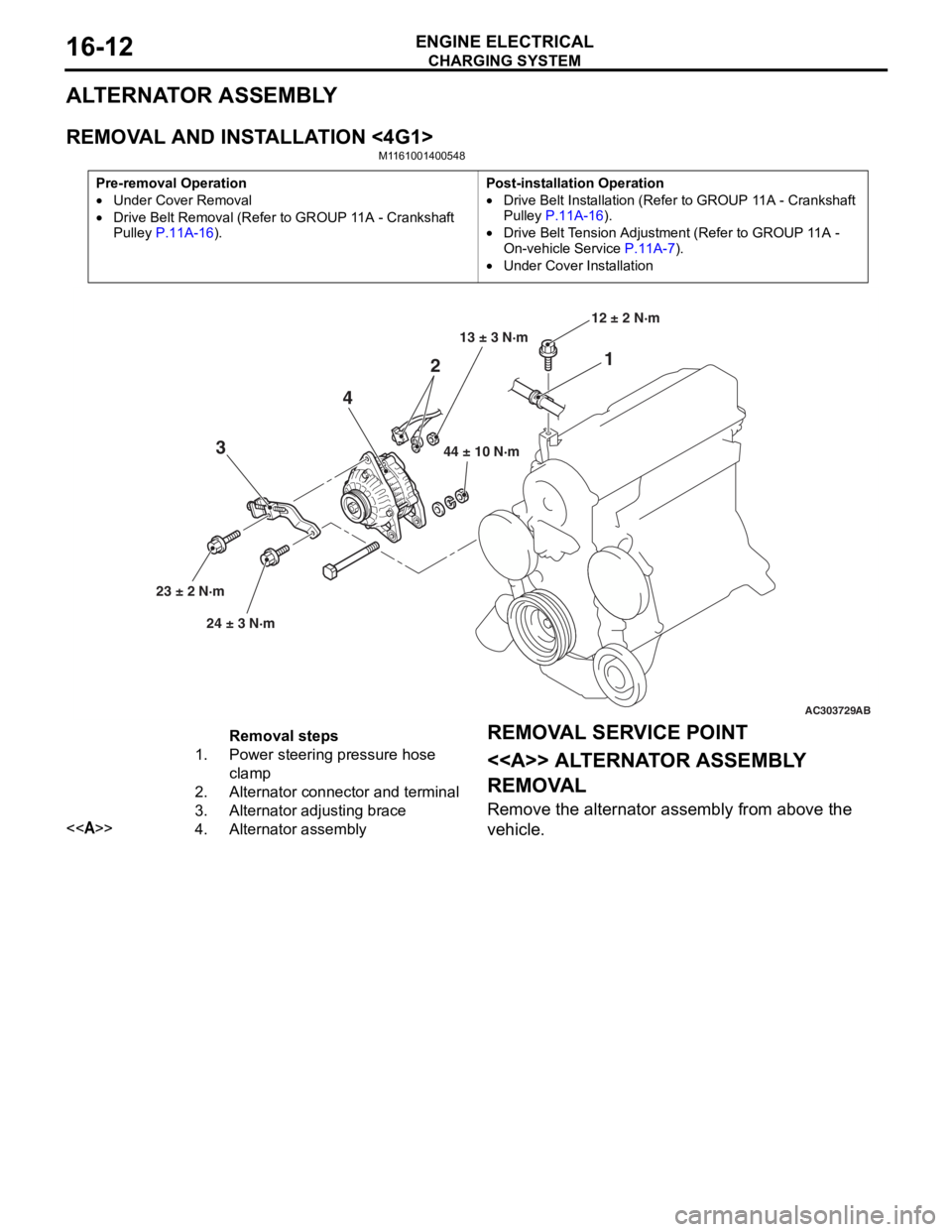
REMOVAL AND INSTALLATION <4G1>
M1161001400548
Pre-removal Operation
•Under Cover Removal
•Drive Belt Removal (Refer to GROUP 11A - Crankshaft
Pulley
P.11A-16).
Post-installation Operation
•Drive Belt Installation (Refer to GROUP 11A - Crankshaft
Pulley P.11A-16).
•Drive Belt Tension Adjustment (Refer to GROUP 11A -
On-vehicle Service P.11A-7).
•Under Cover Installation
AC303729
1
2
4
3
44 ± 10 N·m
23 ± 2 N·m 24 ± 3 N·m 12 ± 2 N·m
AB
13 ± 3 N·m
Removal steps
1.Power steering pressure hose
clamp
2.Alternator connector and terminal
3.Alternator adjusting brace
<>4.Alternator assembly
REMOV
A L SER VICE POINT
<> ALTERNA T O R ASSEMBL Y
REMOV
A L
Remove the a l tern ator assembly from above the
vehicle.
Page 75 of 800
CHARGING SYSTEM
ENGINE ELECTRICAL16-13
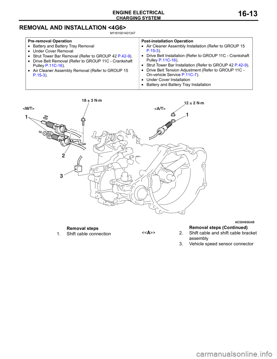
REMOVAL AND INSTALLATION <4G6>
M1161001401347
Pre-removal Operation
•Battery and Battery Tray Removal
•Under Cover Removal
•Strut Tower Bar Removal (Refer to GROUP 42 P.42-9).
•Drive Belt Removal (Refer to GROUP 11C - Crankshaft
Pulley P.11C-16).
•Air Cleaner Assembly Remo val (Refer to GROUP 15 P.15-3).
Post-installation Operation
•Air Cleaner Assembly Installation (Refer to GROUP 15 P.15-3).
•Drive Belt Installation (Refer to GROUP 11C - Crankshaft
Pulley P.11C-16).
•Strut Tower Bar Installation (Refer to GROUP 42 P.42-9).
•Drive Belt Tension Adjustment (Refer to GROUP 11C -
On-vehicle Service
P.11C-7).
•Under Cover Installation
•Battery and Battery Tray Installation
AC504936
1 1
2
3
18 ± 3 N·m 12 ± 2 N·m
AB
Removal steps
1.Shift cable connection<>2.Shift cable and shift cable bracket
assembly
3.Vehicle speed sensor connector
Removal steps (Continued)
Page 76 of 800
AC303827
65
84
9
7
22 ± 4 N·m
23 ± 3 N·m
8.8 ± 1.0 N·m 44 ± 10 N·m
AB
13 ± 3 N·m
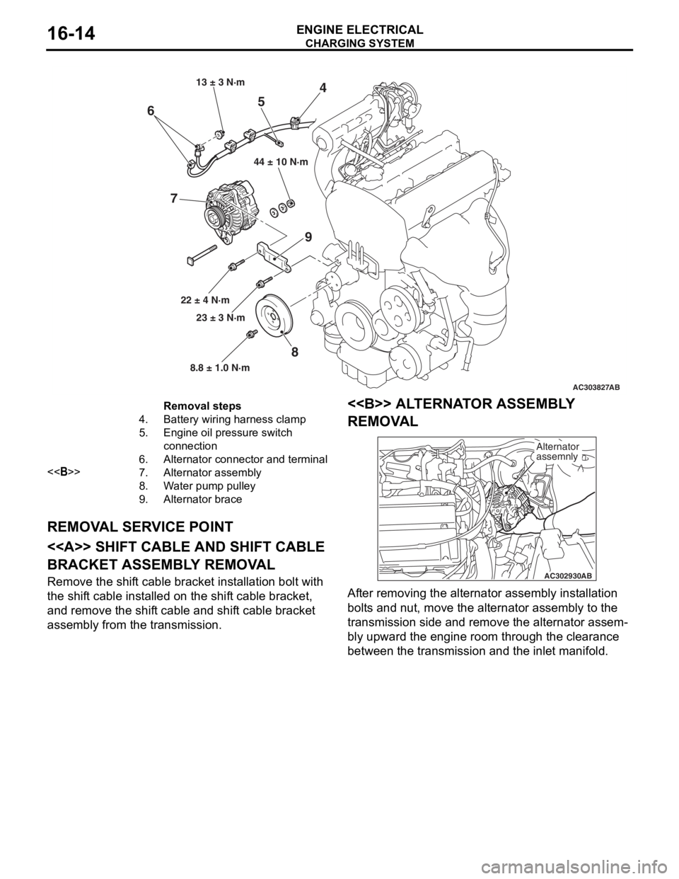
Removal steps
4.Battery wiring harness clamp
5.Engine oil pressure switch
connection
6.Alternator connector and terminal
<>7.Alternator assembly
8.Water pump pulley
9.Alternator brace
CHARGING SYSTEM
ENGINE ELECTRICAL16-14
REMOV
A L SER V ICE POINT
<> SHIFT CABLE AND SHIFT CABLE
BRACKET ASSEMBL
Y REMOV A L
Remove the shift cable bracket inst allation bolt with
the shif
t ca ble inst alled o n the shif t cable bracket,
and remove
the shif t cable and shif t cable bracket
assembly fro
m the transmission.
<> ALTERNA T O R ASSEMBL Y
REMOV
A L
AC302930 AB
Alternator
assemnly
Af
ter re moving the alternato r assembly inst allation
bolt
s a nd nu t, move the alte rnator a sse mbly to the
transmission side an
d remove the alternato r assem
-
bly upward the engine roo m thr ough th e clearan ce
between t
he tran smission and the inlet ma nifold.
Page 77 of 800
CHARGING SYSTEM
ENGINE ELECTRICAL16-15
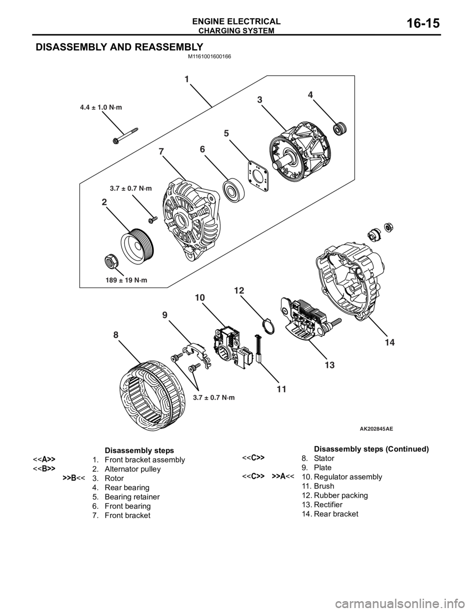
DISASSEMBLY AND REASSEMBLY
M1161001600166
AK202845
1
2 3
4
5
6
7
8 9
10
11
12
1314
AE
4.4 ± 1.0 N·m
3.7 ± 0.7 N·m
189 ± 19 N·m
3.7 ± 0.7 N·m
Disassembly steps
<>1.Front bracket assembly
<>2.Alternator pulley
>>B<<3.Rotor
4.Rear bearing
5.Bearing retainer
6.Front bearing
7.Front bracket
<
9.Plate
<
11 .Brush
12.Rubber packing
13.Rectifier
14.Rear bracket
Disassembly steps (Continued)
Page 78 of 800
Page 79 of 800
CHARGING SYSTEM
ENGINE ELECTRICAL16-17
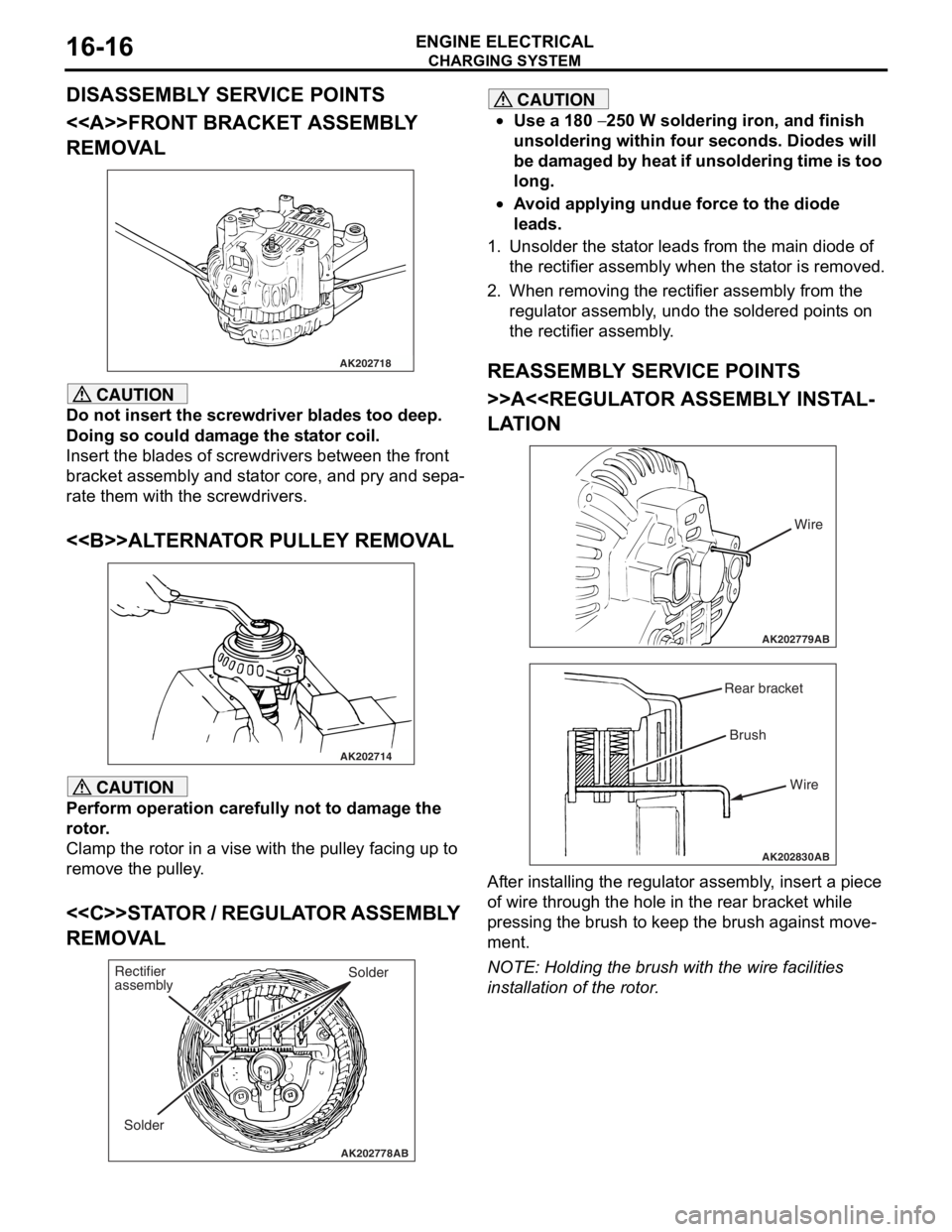
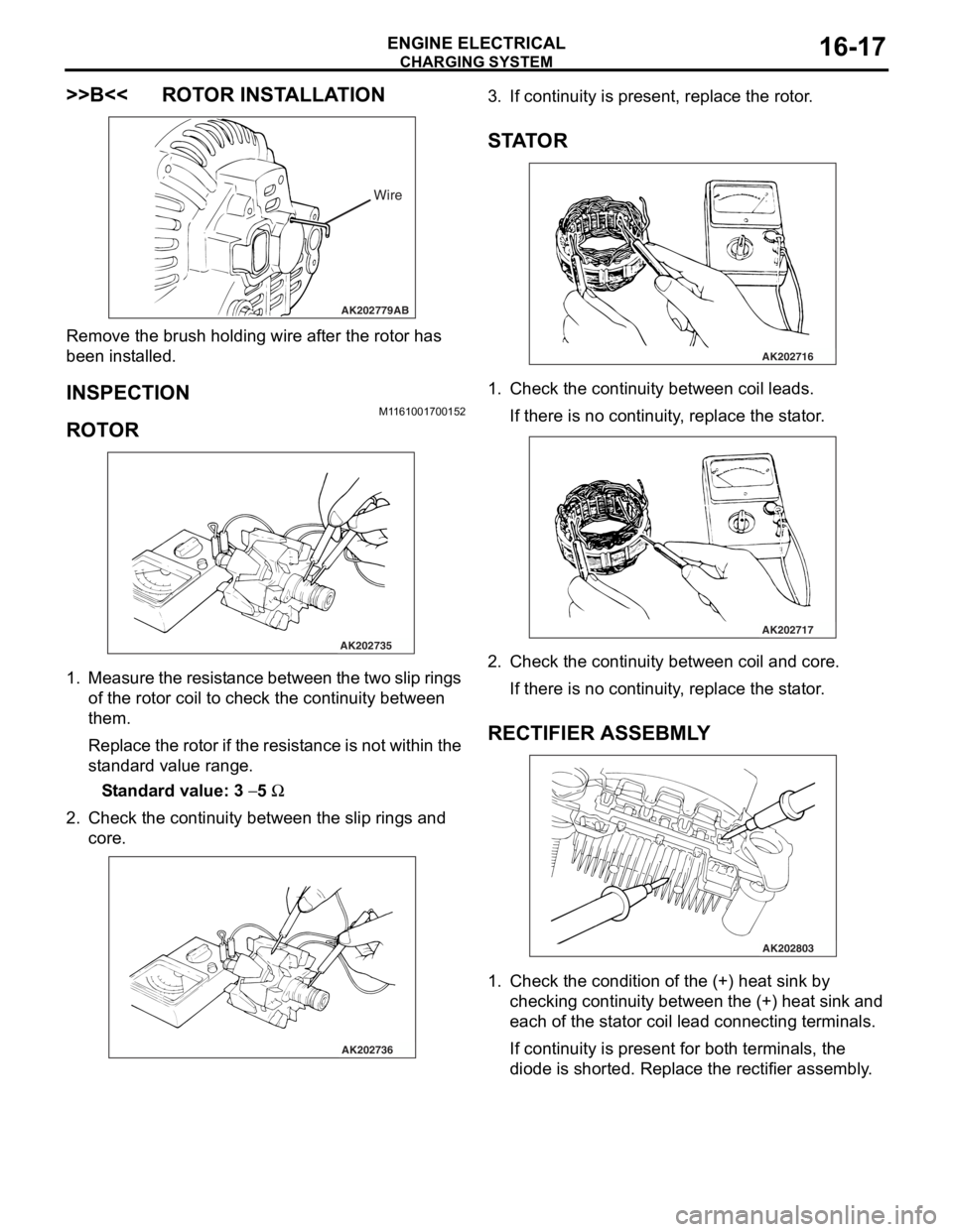
>>B<< ROTOR INSTALLATION
AK202779
Wire
AB
Remove the br ush holding wire af ter the rotor ha s
been inst
alled.
INSPECTION
M1161 0017 0015 2
ROTO R
AK202735
1. Measure th e resist a n ce b e tween the two slip rings
of the rot o r coil to check t he co ntinu i ty between
th em.
Repla c e th e r o to r if th e resist ance is no t within the
st
a ndard valu e range .
St andard va lue: 3 − 5 Ω
2.Check t he co ntinu i ty between the slip rings and
core.
AK202736
3. If cont inuity is pre s ent, repla c e th e rotor .
STA T OR
AK202716
1.Check t he co ntinu i ty between coil le ads.
If there is no con t inuity , replace the st a t or .
AK202717
2.Check t he co ntinu i ty between coil and core .
If there is no con t inuity , replace the st a t or .
RECTIFIER ASSEBMLY
AK202803
1.Check t he co ndition o f the (+) h eat sink by
checkin g contin uity be twe en t he (+) heat sink and
e a ch o f the st a t or coil lead conn ecting termina l s.
If cont inuity is pre s ent for both terminals, the
d
i ode is shorte d. Repla c e th e rectifie r assembly .
Page 80 of 800
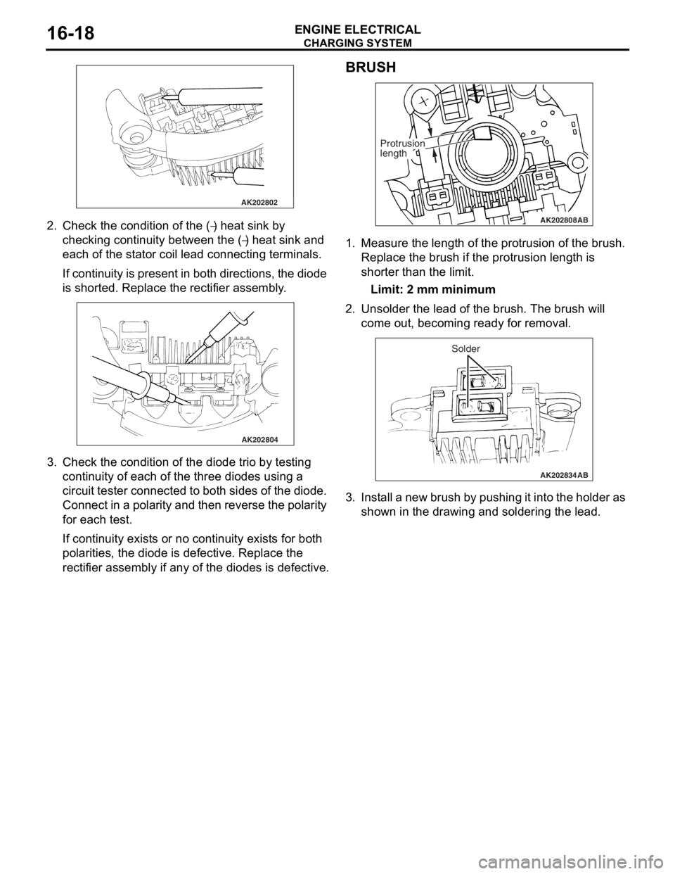
AK202802
CHARGING SYSTEM
ENGINE ELECTRICAL16-18
2.Check t he co ndition of the (−) heat sink by
checkin
g
con
t
inuity b
e
tween th e (
−) he at sink and
ea
ch o
f
the st
a
t
or co
il lead conne
cting termina l s.
If con t inu i ty is p r ese n t in bot h d i re ctio ns, the dio de
is shorted.
Re place the rectifier assembly .
AK202804
3.Check t he co ndition of the diode t r io by testing
continuity of ea ch o f the th ree diodes using a
circuit tester con necte d to both sides of the dio de.
Co nnect in a p o la rity a nd then reverse the polarity
fo r each test.
If continuity exist s or no cont inuity exist s for bo th
po
larities, the d i ode is d e fective . Repla c e th e
rectifier assembly if a
n y o f the d i odes is defe c tive.
BRUSH
AK202808
Protrusion
length
AB
1.Measure the lengt h of the prot rusion o f the bru s h.
Replace the b r ush if the protrusion lengt h is
shorter than th e limit .
Limit: 2 mm mini mum
2.Unsolde r the lead o f the br ush. The bru s h will
come out, b e coming ready for removal.
AK202834
Solder
AB
3.I n st all a ne w b r ush b y pu sh in g it int o the h o lde r a s
shown in the d r awing a nd soldering th e lea d .