Special tool MITSUBISHI LANCER 2006 Repair Manual
[x] Cancel search | Manufacturer: MITSUBISHI, Model Year: 2006, Model line: LANCER, Model: MITSUBISHI LANCER 2006Pages: 800, PDF Size: 45.03 MB
Page 262 of 800
POWER STEERING GEAR BOX AND LINKAGE
POWER STEERING37-32
3. Wrap the rack end with plastic tape, and push the rack bushing onto the rack.
>>E<< CIRCLIP INSTALLATION
CAUTION
Insert the circlip to the rack stopper hole while
turning the rack stopper clockwise.
ACX01158
Circlip
Slot
AB
Circlip
Slot
Insert the circlip to the rack stopper hole through cyl-
inder hole. Turn the rack stopper clockwise and
insert the circlip firmly.
>>F<< UPPER OIL SEAL/UPPER
BEARING INSTALLATION
ACX01159AC
MB990938
MB991203
Oil seal
MB991203 Bearing
MB990938
Apply a coating of ATF DEXRON III or DEXRON II to
the outside of the upper oil seal/upper bearing. Using
the following special tools, press the upper oil
seal/upper bearing into the valve housing.
•Bar (snap-in type) (MB990938)
•Oil seal and bearing Installer (MB991203)
>>G<< SEAL RINGS INSTALLATION
ACX01160
AB
MB991317
Because the seal rings expand after installation,
tighten after installing by using special tool seal ring
installer (MB991317) to compress the rings, or press
down by hand.
>>H<< LOWER OIL SEAL INSTALLATION
ACX01161
Housing
AC
Oil
seal
Approximately
1 mm
MB990941
CAUTION
To eliminate a seal malfunction at the valve hous-
ing alignment surface, the upper surface of the
oil seal should project outward approximately 1
mm from the housing edge surface.
Using special tool torque tube bearing installer
(MB990941), press the oil seal into the valve hous
-
ing.
>>I<< END PLUG INSTALLATION
ACX01162
AB
End plug End plug
1. Apply specified sealant to the threaded part of the
end plug.
Page 263 of 800
POWER STEERING GEAR BOX AND LINKAGE
POWER STEERING37-33
Specified sealant: 3M ATD Part No.8661 or
equivalent
2. Secure the threaded portion of the end plug at two places by using a punch.
>>J<< RACK SUPPORT COVER/LOCK
NUT INSTALLATION
1. Position the rack at its centre.
2. Apply specified sealant to the threaded part of the
rack support cover.
Specified sealant:
3M ATD Part No.8661 or equivalent
AC100273
MB990607
MB991621
AJ
3.Use the fo llo wing special to ol to tigh ten the rack
suppor t cover to 2 3
± 2 N⋅m.
•To rque wren ch socket (MB990607 )
•Piston driver (MB9916 21:
4.T u rn the rack suppo rt cover 30° anticlockwise .
5.Use the special tool to hold the r a ck sup port
cove r , and t hen tighten the lock nut to 59
± 10
N
⋅m.
>>K<< T O T A L PINION T O RQUE
ADJUSTMENT
CAUTION
•Be sure there is no ratcheting or catching
when operating the rack towards the shaft.
•
AC100274 AB
MB991006
Measure the total pinion torque through the
whole stroke of the rack.
1. Using special tool preload socket (MB991006),
rotate the pinion shaft at the rate of one rotation in
4 to 6 seconds to check the total pinion torque and
the change in torque.
Standard value:
Total pinion torque: 0.8 − 2.1 N⋅m
[Change in torque: 0.6 N
⋅m or less]
Total pinion torque: 0.7 − 2.1 N⋅m
[Change in torque: 0.6 N
⋅m or less]
CAUTION
When adjusting, set at the highest value of the
standard value range.
NOTE: If the total pinion toque cannot be adjusted
to the standard value within the specified return
angle, check the rack support cover components
and replace any parts if necessary.
2. If the total pinion torque or the change in torque is outside the standard value, move the rack support
cover 0
− 30°, and adjust the pinion torque again.
>>L<< TAB WASHER/TIE ROD
INSTALLATION
ACX01163 AB
After installing the tie rod to the rack, fold tab washer
end (two locations) to tie rod notch.
>>M<< BELLOWS BAND INSTALLATION
ACX01164 AB
W MB991561
Adjusting bolt Stopper
1. Turn the adjusting bolt of special tool boot band
crimping tool (MB991561) to adjust the opening
dimension (W) to the standard value.
Page 264 of 800
POWER STEERING GEAR BOX AND LINKAGE
POWER STEERING37-34
NOTE: The dimension (W) is adjusted by approxi-
mately 0.7 mm per one turn.
NOTE: Do not turn the adjusting bolt more than
one turn.
Standard value (W): 2.9 mm
adjusting bolt.
adjusting bolt.
CAUTION
•Hold the rack housing, and use special tool to
crimp the bellows band securely.
•
ACX01165AB
MB991561
Crimp the bellows band until special tool
touches the stopper.
2. Use special tool boot band crimping tool (MB991561) to crimp the bellows band.
ACX01166 AB
A
3. Check that crimped width (A) is within the
standard value.
Standard value (A): 2.4 − 2.8 mm
dimension (W) of step (1) to the value calcu
-
lated by the following equation, and repeat
step (2).
W = 5.5 mm − A [Example: if (A) is 2.9 mm,
(W) is 2.6 mm.]
lows band, readjust the dimension (W) of
step (1) to the value calculated by the follow
-
ing equation, and use a new bellows band to
repeat steps (2) to (3).
W = 5.5 mm − A [Example: if (A) is 2.3 mm,
(W) is 3.2 mm.]
>>N<< TIE ROD END/LOCK NUT
INSTALLATION
AC001011 AM
Lock nut
Edge of bellows
assembly groove
180 mm
Screw in the tie rod end to achieve the right and left
length as illustrated. Lock with the lock nut.
NOTE: The lock nuts must be tightened securely
only after the steering gear is installed to the vehicle
and toe-in is adjusted.
>>O<< GEAR MOUNTING RUBBER
INSTALLATION
AC100275 AB
220 mm
Install the gear mounting rubber to the rack housing
so that the distance is as shown in the illustration.
Page 265 of 800
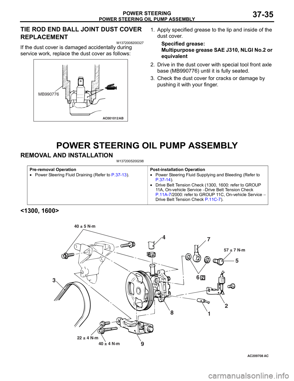
POWER STEERING OIL PUMP ASSEMBLY
POWER STEERING37-35
TIE ROD END BALL JOINT DUST COVER
REPLACEMENT
M1372008200327
If the dust cover is damaged accidentally during
service work, replace the dust cover as follows:
AC001012AB
MB990776
1.App l y specified grea se to the lip an d inside of the
d u st c o ve r .
Specified grease:
Mu l t i p u r po se g r ea se SAE J3 10 , NL GI No .2 or
equival
ent
2.Drive in the d u st cover with special tool f r ont axle
b a se (MB9907 76) unt il it is fully seated .
3.Check t he dust co ver f o r cracks or da mage by
p u shing it with your finger .
POWER STEERING OIL PUMP ASSEMBL Y
REMOVA L AND INST ALLA TIONM13720052 0029 8
Pre-removal Operation
•Power Steering Fluid Draining (Refer to P.37-13).
Post-installation Operation
•Power Steering Fluid Supplying and Bleeding (Refer to
P.37-14).
•Drive Belt Tension Check (1300, 1600: refer to GROUP
11A, On-vehicle Service
− Drive Belt Tension Check
P.11A-7/2000: refer to GROUP 11C, On-vehicle Service − Drive Belt Tension Check P.11C-7).
<1300, 1600>
AC209708
87
1 2
3 4
5
6
57 ± 7 N·m
40 ± 4 N·m
22 ± 4 N·m
N
9
40 ± 5 N·m
AC
Page 273 of 800
42-1
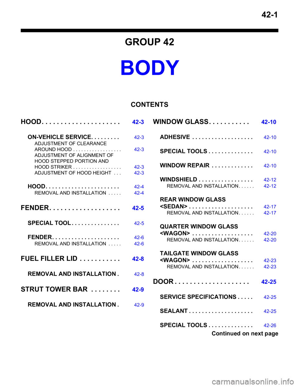
GROUP 42
BODY
CONTENTS
HOOD . . . . . . . . . . . . . . . . . . . . .42-3
ON-VEHICLE SERVICE. . . . . . . . .42-3
ADJUSTMENT OF CLEARANCE
AROUND HOOD . . . . . . . . . . . . . . . . . . 42-3
ADJUSTMENT OF ALIGNMENT OF
HOOD STEPPED PORTION AND
HOOD STRIKER . . . . . . . . . . . . . . . . . . 42-3
ADJUSTMENT OF HOOD HEIGHT . . . 42-3
HOOD . . . . . . . . . . . . . . . . . . . . . . .42-4
REMOVAL AND INSTALLATION . . . . . 42-4
FENDER . . . . . . . . . . . . . . . . . . .42-5
SPECIAL TOOL . . . . . . . . . . . . . . .42-5
FENDER . . . . . . . . . . . . . . . . . . . . .42-6
REMOVAL AND INSTALLATION . . . . . 42-6
FUEL FILLER LID . . . . . . . . . . .42-8
REMOVAL AND INSTALLATION .42-8
STRUT TOWER BAR . . . . . . . .42-9
REMOVAL AND INSTALLATION .42-9
WINDOW GLASS . . . . . . . . . . . 42-10
ADHESIVE . . . . . . . . . . . . . . . . . . .42-10
SPECIAL TOOLS . . . . . . . . . . . . . .42-10
WINDOW REPAIR . . . . . . . . . . . . .42-10
WINDSHIELD . . . . . . . . . . . . . . . . .42-12
REMOVAL AND INSTALLATION . . . . . . 42-12
REAR WINDOW GLASS
REMOVAL AND INSTALLATION . . . . . . 42-17
QUARTER WINDOW GLASS
REMOVAL AND INSTALLATION . . . . . . 42-20
TAILGATE WINDOW GLASS
REMOVAL AND INSTALLATION . . . . . . 42-23
DOOR . . . . . . . . . . . . . . . . . . . . 42-25
SERVICE SPECIFICA TIONS . . . . .42-25
SEALANT . . . . . . . . . . . . . . . . . . . .42-25
SPECIAL TOOLS . . . . . . . . . . . . . .42-26
Continued on next page
Page 274 of 800
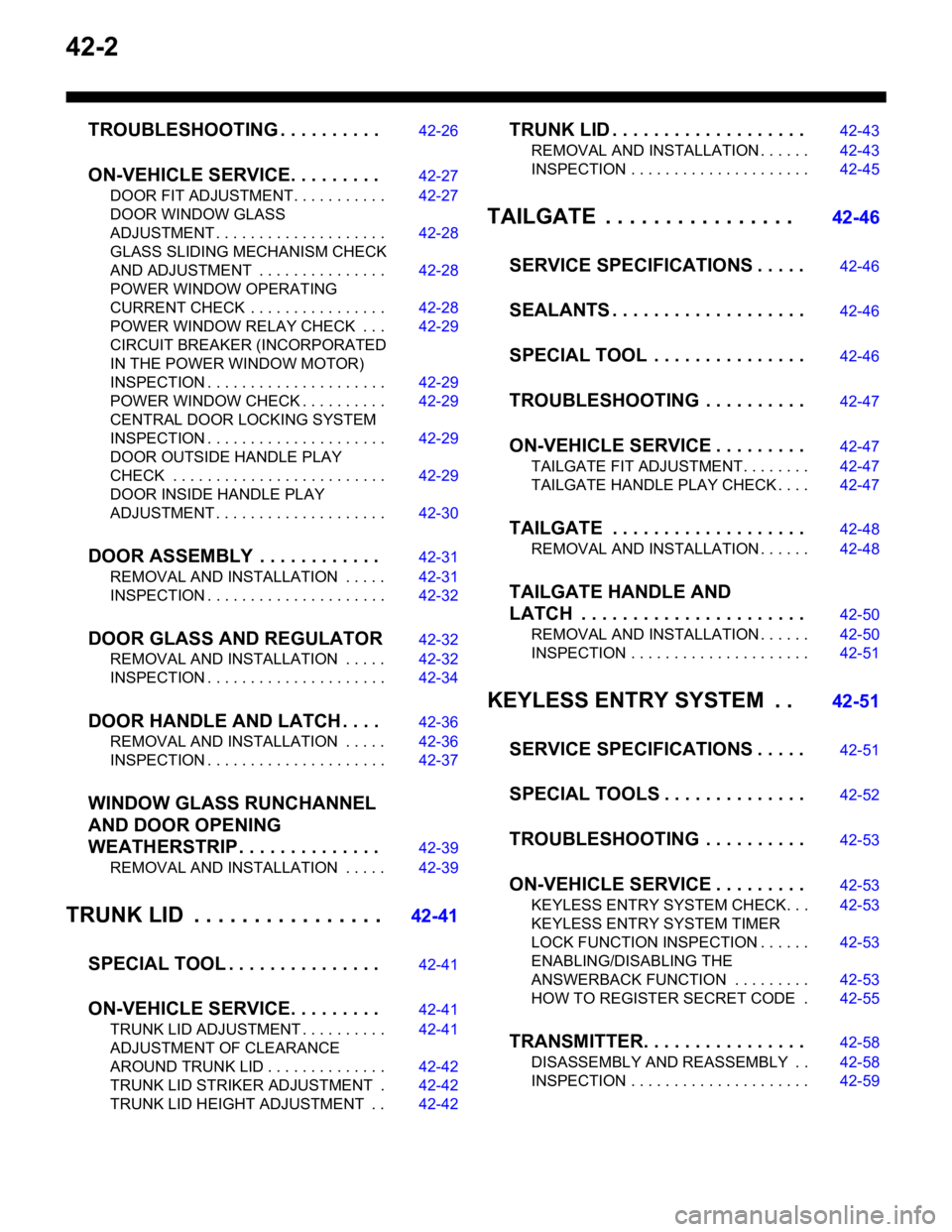
42-2
TROUBLESHOOTING . . . . . . . . . .42-26
ON-VEHICLE SERVICE. . . . . . . . .42-27
DOOR FIT ADJUSTMENT. . . . . . . . . . . 42-27
DOOR WINDOW GLASS
ADJUSTMENT . . . . . . . . . . . . . . . . . . . . 42-28
GLASS SLIDING MECHANISM CHECK
AND ADJUSTMENT . . . . . . . . . . . . . . . 42-28
POWER WINDOW OPERATING
CURRENT CHECK . . . . . . . . . . . . . . . . 42-28
POWER WINDOW RELAY CHECK . . . 42-29
CIRCUIT BREAKER (INCORPORATED
IN THE POWER WINDOW MOTOR)
INSPECTION . . . . . . . . . . . . . . . . . . . . . 42-29
POWER WINDOW CHECK . . . . . . . . . . 42-29
CENTRAL DOOR LOCKING SYSTEM
INSPECTION . . . . . . . . . . . . . . . . . . . . . 42-29
DOOR OUTSIDE HANDLE PLAY
CHECK . . . . . . . . . . . . . . . . . . . . . . . . . 42-29
DOOR INSIDE HANDLE PLAY
ADJUSTMENT . . . . . . . . . . . . . . . . . . . . 42-30
DOOR ASSEMBLY . . . . . . . . . . . .42-31
REMOVAL AND INSTALLATION . . . . . 42-31
INSPECTION . . . . . . . . . . . . . . . . . . . . . 42-32
DOOR GLASS AND REGULATOR42-32
REMOVAL AND INSTALLATION . . . . . 42-32
INSPECTION . . . . . . . . . . . . . . . . . . . . . 42-34
DOOR HANDLE AND LATCH . . . .42-36
REMOVAL AND INSTALLATION . . . . . 42-36
INSPECTION . . . . . . . . . . . . . . . . . . . . . 42-37
WINDOW GLASS RUNCHANNEL
AND DOOR OPENING
WEATHERSTRIP . . . . . . . . . . . . . .42-39
REMOVAL AND INSTALLATION . . . . . 42-39
TRUNK LID . . . . . . . . . . . . . . . .42-41
SPECIAL TOOL . . . . . . . . . . . . . . .42-41
ON-VEHICLE SERVICE. . . . . . . . .42-41
TRUNK LID ADJUSTMENT . . . . . . . . . . 42-41
ADJUSTMENT OF CLEARANCE
AROUND TRUNK LID . . . . . . . . . . . . . . 42-42
TRUNK LID STRIKER ADJUSTMENT . 42-42
TRUNK LID HEIGHT ADJUSTMENT . . 42-42
TRUNK LID . . . . . . . . . . . . . . . . . . .42-43
REMOVAL AND INSTALLATION . . . . . . 42-43
INSPECTION . . . . . . . . . . . . . . . . . . . . . 42-45
TAILGATE . . . . . . . . . . . . . . . . 42-46
SERVICE SPECIFICATIONS . . . . .42-46
SEALANTS . . . . . . . . . . . . . . . . . . .42-46
SPECIAL TOOL . . . . . . . . . . . . . . .42-46
TROUBLESHOOTING . . . . . . . . . .42-47
ON-VEHICLE SERVICE . . . . . . . . .42-47
TAILGATE FIT ADJUSTMENT. . . . . . . . 42-47
TAILGATE HANDLE PLAY CHECK . . . . 42-47
TAILGATE . . . . . . . . . . . . . . . . . . .42-48
REMOVAL AND INSTALLATION . . . . . . 42-48
TAILGATE HANDLE AND
LATCH . . . . . . . . . . . . . . . . . . . . . .42-50
REMOVAL AND INSTALLATION . . . . . . 42-50
INSPECTION . . . . . . . . . . . . . . . . . . . . . 42-51
KEYLESS ENTRY SYSTEM . . 42-51
SERVICE SPECIFICATIONS . . . . .42-51
SPECIAL TOOLS . . . . . . . . . . . . . .42-52
TROUBLESHOOTING . . . . . . . . . .42-53
ON-VEHICLE SERVICE . . . . . . . . .42-53
KEYLESS ENTRY SYSTEM CHECK. . . 42-53
KEYLESS ENTRY SYSTEM TIMER
LOCK FUNCTION INSPECTION . . . . . . 42-53
ENABLING/DISABLING THE
ANSWERBACK FUNCTION . . . . . . . . . 42-53
HOW TO REGISTER SECRET CODE . 42-55
TRANSMITTER. . . . . . . . . . . . . . . .42-58
DISASSEMBLY AND REASSEMBLY . . 42-58
INSPECTION . . . . . . . . . . . . . . . . . . . . . 42-59
Page 277 of 800
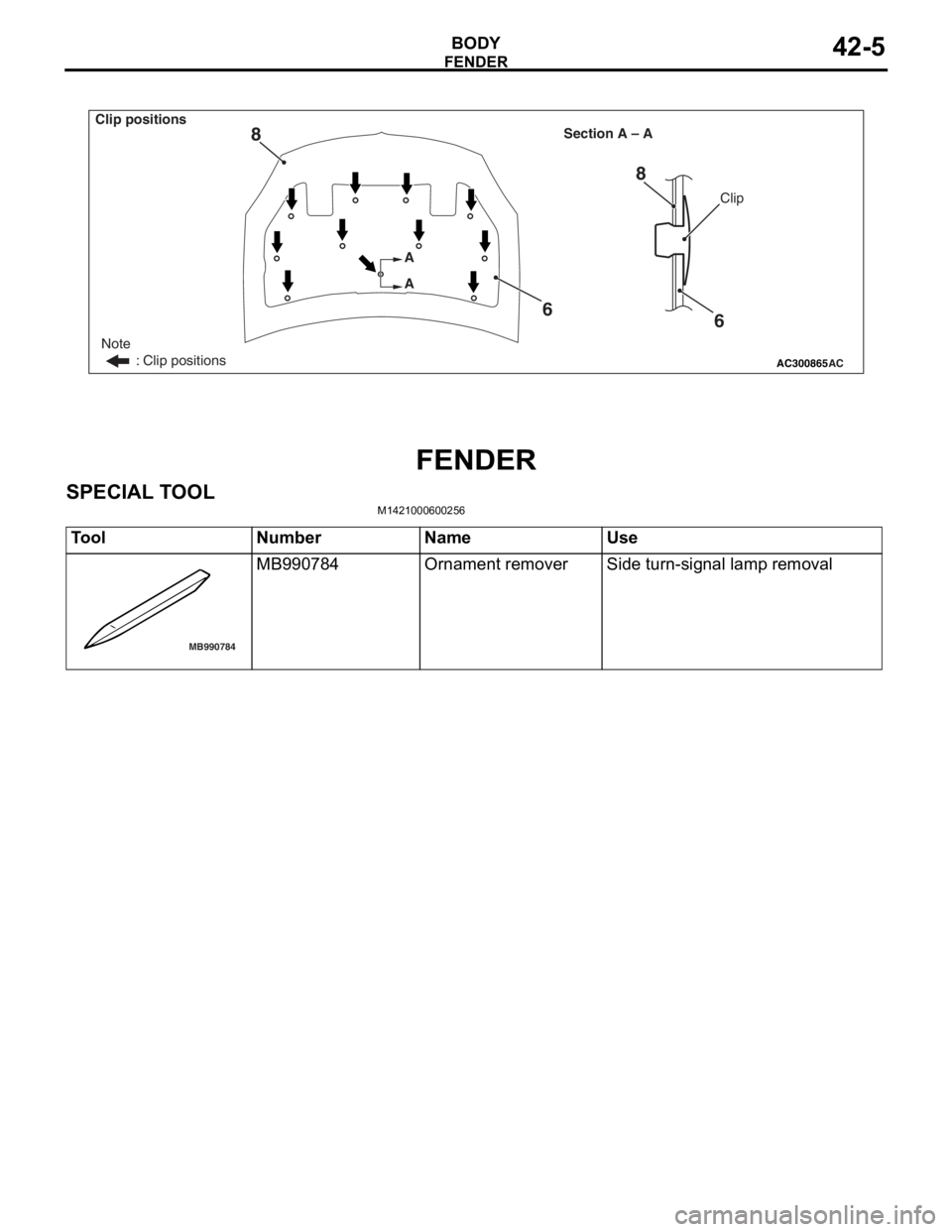
AC300865
Note
: Clip positions
Section A – A
AC
Clip
A
A
6
8
6
8
Clip positions
FEN
D ER
BOD Y42-5
FENDER
SPECIAL T O OL
M14210006 0025 6
ToolNumberNameUse
MB990784
MB990784Ornament removerSide turn-signal lamp removal
Page 282 of 800
WINDOW GLASS
BODY42-10
WINDOW GLASS
ADHESIVEM1422000500081
ItemSpecified adhesive
Windshield3M ATD Part No.8609 Super Fast Urethane Auto Glass
Sealant or equivalent
3M ATD Part No.8608 Super Fast Urethane Primer or
equivalentRear window glass
Quarter window glass
Tailgate window glass
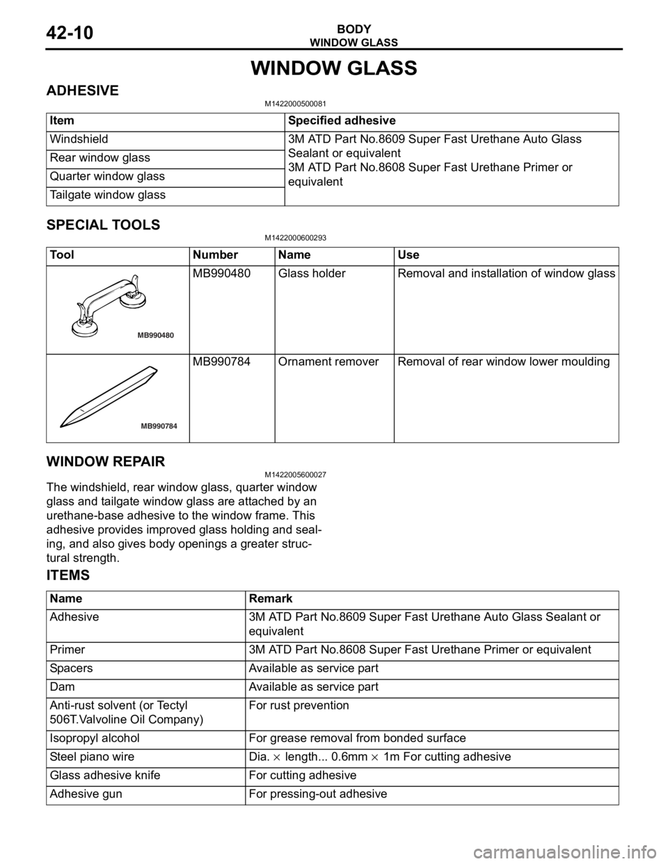
SPECIAL TOOLS
M1422000600293
ToolNumberNameUse
MB990480
MB990480Gl as s h o l de rRemoval and inst a llat i on of wind ow glass
MB990784
MB990784Ornament removerRemoval of rea r window lower mo ulding
WI NDOW REP A IR
M14220056 0002 7
The windshield, rear wind ow glass, q uarter window
glass an
d t a ilg ate win dow gla ss a r e att a ched by an
urethan
e-base adhe sive to the wind ow frame . This
adhesive provides improv
ed glass hold i ng a nd seal
-
ing, and also g i ve s bod y op ening s a g r eater struc-
tural strength.
ITEMS
NameRemark
Adhesive3M ATD Part No.8609 Super Fast Urethane Auto Glass Sealant or
equivalent
Primer3M ATD Part No.8608 Super Fast Urethane Primer or equivalent
SpacersAvailable as service part
DamAvailable as service part
Anti-rust solvent (or Tectyl
506T.Valvoline Oil Company)For rust prevention
Isopropyl alcoholFor grease removal from bonded surface
Steel piano wireDia. × length... 0.6mm × 1m For cutting adhesive
Glass adhesive knifeFor cutting adhesive
Adhesive gunFor pressing-out adhesive
Page 285 of 800
Removal steps
•Roof drip moulding (Refer to GROUP
51, Moulding
P.51-9.)
<>>>B<<1.Windshield
>>A<<2.Windshield moulding
>>A<<3.Window dam
>>A<<4.Glass stopper
>>A<<5.Spa cer
>>A<<6.Windshield spacer
WI NDOW GLASS
BO D Y42-13
REMOV A L SER V ICE POINT
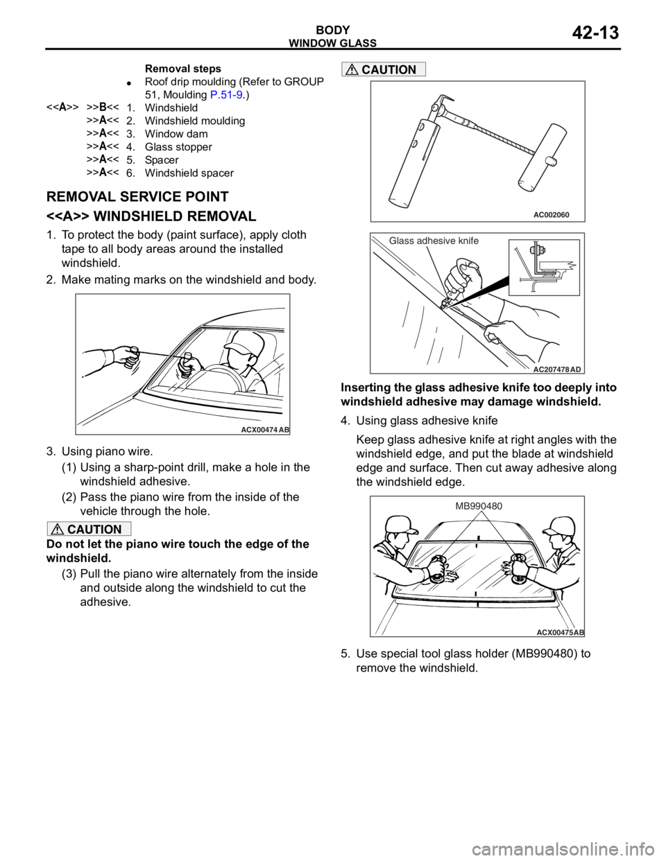
<> WI NDSHIELD REMOV A L
1.T o prot ect th e body (p ain t surfa c e), a pply cloth
t ape to all bod y area s aro und th e inst a lle d
windshield.
2.Make mating marks on th e windshie l d an d body .
ACX00474
AB
3.Using p i ano wire.
(1)U sin g a sharp-po int d r ill, make a h o le in the
windshield ad hesive.
(2)P ass the p i ano wire from the inside of the
veh i cle thro ugh the hole.
CAUTION
Do not let the piano wire touch the edge of the
windshield.
(3) Pull the piano wire alternately from the inside and outside along the windshield to cut the
adhesive.
AC002060
AC207478
Glass adhesive knife
AD
CAUTION
Inserting the glass adhesive knife too deeply into
windshield adhesive may damage windshield.
4. Using glass adhesive knife
Keep glass adhesive knife at right angles with the
windshield edge, and put the blade at windshield
edge and surface. Then cut away adhesive along
the windshield edge.
ACX00475 AB
MB990480
5. Use special tool glass holder (MB990480) to
remove the windshield.
Page 290 of 800
