Egr MITSUBISHI LANCER 2006 Workshop Manual
[x] Cancel search | Manufacturer: MITSUBISHI, Model Year: 2006, Model line: LANCER, Model: MITSUBISHI LANCER 2006Pages: 800, PDF Size: 45.03 MB
Page 8 of 800

GENERAL INFORMATION
ENGINE LUBRICATION12-2
GENERAL INFORMATION
M1121000100357
The lubrication method is a fully force-fed, full-flow fil-
tration type. The engine oil pump is a trochoid type
which is driven by the crankshaft <4G1>.The engine
oil pump is a gear type which is driven by the crank
-
shaft via the balancer timing belt <4G6>.
ENGINE OILS
Health Warning
Prolonged and repeated contact with mineral oil will
result in the removal of natural fats from the skin,
leading to dryness, irritation and dermatitis. In addi
-
tion, used engine oil contains potentially harmful con-
taminants which may cause skin cancer. Adequate
means of skin protection and washing facilities must
be provided.
Recommended Precautions
The most effective precaution is to adapt working
practices which prevent, as far as practicable, the
risk of skin contact with mineral oils, for example by
using enclosed systems for handling used engine oil
and by degreasing components, where practicable,
before handling them. Other precautions:
•Avoid prolonged and repeated contact with oils,
particularly used engine oils.
•Wear protective clothing, including impervious
gloves where practicable.
•Avoid contaminating clothes, particularly under-
pants, with oil.
•Do not put oily rags in pockets, the use of overalls
without pockets will avoid this.
•Do not wear heavily soiled clothing and
oil-impregnated foot-wear. Overalls must be
cleaned regularly and kept separate from per
-
sonal clothing.
•Where there is a risk of eye contact, eye protec-
tion should be worn, for example, chemical gog-
gles or face shields; in addition an eye wash
facility should be provided.
•Obtain first aid treatment immediately for open
cuts and wounds.
•Wash regularly with soap and water to ensure all
oil is removed, especially before meals (skin
cleansers and nail brushes will help). After clean
-
ing, the application of preparations containing
lanolin to replace the natur al skin oils is advised.
•Do not use petrol, kerosine, diesel fuel, gas oil,
thinners or solvents for cleaning skin.
•Use barrier creams, applying them before each
work period, to help the removal of oil from the
skin after work.
•If skin disorders develop, obtain medical advice
without delay.
SERVICE SPECIFICATION
M1121000300232
ItemStandard value
Oil pressure kPaat idle29 or more
at 3,500 r/min294 − 686
LUBRICANT
M1121000400433
ItemSpecification
Engine oil ACEA classificationA1, A2 or A3
Engine oil API classificationSG or higher
Engine oil quantity L4G1Oil filter0.3
To t a l3.3
4G6Oil filter0.3
To t a l4.3
Page 55 of 800
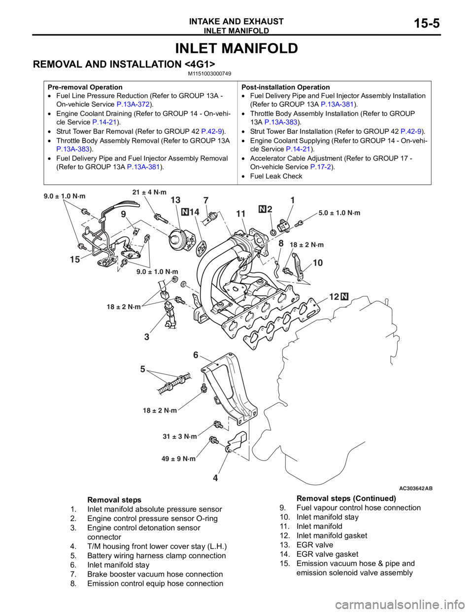
INLET MANIFOLD
INTAKE AND EXHAUST15-5
INLET MANIFOLD
REMOVAL AND INSTALLATION <4G1>M1151003000749
Pre-removal Operation
•Fuel Line Pressure Reduction (Refer to GROUP 13A -
On-vehicle Service
P.13A-372).
•Engine Coolant Draining (Refer to GROUP 14 - On-vehi-
cle Service P.14-21).
•Strut Tower Bar Removal (Refer to GROUP 42 P.42-9).
•Throttle Body Assembly Re moval (Refer to GROUP 13A
P.13A-383).
•Fuel Delivery Pipe and Fuel Injector Assembly Removal
(Refer to GROUP 13A
P.13A-381).
Post-installation Operation
•Fuel Delivery Pipe and Fuel Injector Assembly Installation
(Refer to GROUP 13A
P.13A-381).
•Throttle Body Assembly Inst allation (Refer to GROUP
13A
P.13A-383).
•Strut Tower Bar Installati on (Refer to GROUP 42 P.42-9).
•Engine Coolant Supplying (Refer to GROUP 14 - On-vehi-
cle Service P.14-21).
•Accelerator Cable Adjustment (Refer to GROUP 17 -
On-vehicle Service
P.17-2).
•Fuel Leak Check
AC303642AB
15
36
5
4 12
10
7
1
2
11
9 13
14
21 ± 4 N·m
9.0 ± 1.0 N·m
9.0 ± 1.0 N·m
18 ± 2 N·m
18 ± 2 N·m 18 ± 2 N·m
5.0 ± 1.0 N·m
31 ± 3 N·m
49 ± 9 N·m
N
N
N
8
Removal steps
1.Inlet manifold absolute pressure sensor
2.Engine control pressure sensor O-ring
3.Engine control detonation sensor
connector
4.T/M housing front lower cover stay (L.H.)
5.Battery wiring harness clamp connection
6.Inlet manifold stay
7.Brake booster vacuum hose connection
8.Emission control equip hose connection
9.Fuel vapour control hose connection
10.Inlet manifold stay
11 .Inlet manifold
12.Inlet manifold gasket
13.EGR valve
14.EGR valve gasket
15.Emission vacuum hose & pipe and
emission solenoid valve assembly
Removal steps (Continued)
Page 57 of 800
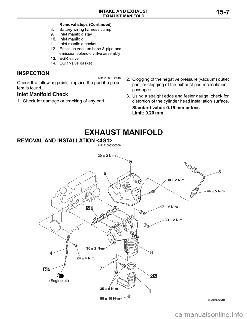
EXHAUST MANIFOLD
INTAKE AND EXHAUST15-7
INSPECTION
M1151003100616
Check the following points; replace the part if a prob-
lem is found.
Inlet Manifold Check
1. Check for damage or cracking of any part.
2. Clogging of the negative pressure (vacuum) outlet port, or clogging of the exhaust gas recirculation
passages.
3. Using a straight edge and feeler gauge, check for distortion of the cylinder head installation surface.
Standard value: 0.15 mm or less
Limit: 0.20 mm
EXHAUST MANIFOLD
REMOVAL AND INSTALLATION <4G1>
M1151003300568
AC30366250 ± 10 N·m
24 ± 4 N·m
35 ± 6 N·m 17 ± 2 N·m
30 ± 2 N·m
N
3
7 12
4
N
6
8
44 ± 5 N·m
AB
9
5N
30 ± 2 N·m
30 ± 2 N·m
30 ± 2 N·m
(Engine oil)
8.Battery wirin g ha rne s s clamp
9.Inlet manifold st ay
10.Inlet manifold
11.Inlet manifold gask et
12.Emission vacuu m hose & pipe and
emis
sion s o lenoid valve assembly
13.EGR v a lve
14.EGR v a lve gasket
Remo va l st ep s ( C o n t in u e d)
Page 107 of 800
17-1
GROUP 17
ENGINE AND
EMISSION
CONTROL
CONTENTS
ENGINE CONTROL . . . . . . . . . .17-2
GENERAL INFORMATION . . . . . .17-2
SERVICE SPECIFICATIONS. . . . .17-2
ON-VEHICLE SERVICE. . . . . . . . .17-2
ACCEL CABLE CHECK AND
ADJUSTMENT . . . . . . . . . . . . . . . . . . . . 17-2
ACCELERATOR CABLE AND
PEDAL . . . . . . . . . . . . . . . . . . . . . .17-3
REMOVAL AND INSTALLATION . . . . . 17-3
EMISSION CONTROL MPI . . . .17-4
GENERAL INFORMATION . . . . . .17-4
EMISSION CONTROL DEVICE
REFERENCE TABLE . . . . . . . . . .17-4
SERVICE SPECIFICATION(S) . . .17-5
VACUUM HOSE. . . . . . . . . . . . . . .17-5
VACUUM HOSE PIPING DIAGRAM . . . 17-5
VACUUM CIRCUIT DIAGRAM . . . . . . . 17-7
VACUUM HOSE CHECK. . . . . . . . . . . . 17-7
VACUUM HOSE INSTALLATION . . . . . 17-8
CRANKCASE EMISSION CONTROL
SYSTEM . . . . . . . . . . . . . . . . . . . . .17-8
GENERAL INFORMATION (CRANKCASE
EMISSION CONTROL SYSTEM) . . . . . 17-8
COMPONENT LOCATI ON (CRANKCASE
EMISSION CONTROL SYSTEM) . . . . . 17-9
POSITIVE CRANKCASE VENTILATION SYSTEM
CHECK . . . . . . . . . . . . . . . . . . . . . . . . . 17-9
POSITIVE CRANKCASE VENTILATION (PCV)
VALVE CHECK . . . . . . . . . . . . . . . . . . . 17-9
EVAPORATIVE EMISSION CONTROL
SYSTEM . . . . . . . . . . . . . . . . . . . . .17-9
GENERAL INFORMATION (EVAPORATIVE
EMISSION CONTROL SYSTEM) . . . . . 17-9
COMPONENT LOCATION (EVAPORATIVE
EMISSION CONTROL SYSTEM) . . . . . 17-10
PURGE CONTROL SYSTEM CHECK . . 17-10
PURGE PORT VACUUM CHECK . . . . . 17-11
PURGE CONTROL SOLENOID VALVE
CHECK . . . . . . . . . . . . . . . . . . . . . . . . . . 17-11
FUEL VAPOUR CANISTER REMOVAL
AND INSTALLATION . . . . . . . . . . . . . . . 17-12
EXHAUST GAS RECIRCULATION
(EGR) SYSTEM . . . . . . . . . . . . . . .17-12
GENERAL INFORMATION
(EGR SYSTEM) . . . . . . . . . . . . . . . . . . . 17-12
COMPONENT LOCATION
(EGR SYSTEM) . . . . . . . . . . . . . . . . . . . 17-14
EGR SYSTEM CHECK . . . . . . . . . . . . . 17-15
EGR VALVE CHECK . . . . . . . . . . . . . . . 17-15
EGR PORT VACUUM CHECK <4G1>. . 17-16
EGR PORT VACUUM CHECK <4G6>. . 17-16
EGR CONTROL SOLENOID VALVE
CHECK <4G1> . . . . . . . . . . . . . . . . . . . . 17-16
EGR CONTROL SOLENOID VALVE
CHECK <4G6> . . . . . . . . . . . . . . . . . . . . 17-17
EXHAUST GAS RECIRCULATION (EGR)
VALVE REMOVAL AND I
NSTALLATION . . . . . . . . . . . . . . . . . . . . 17-18
CATALYTIC CONVERTER . . . . . .17-19
REMOVAL AND INSTALLATION
<4G1, 4G6-M/T> . . . . . . . . . . . . . . . . . . 17-19
REMOVAL AND INSTALLATION
<4G6-A/T> . . . . . . . . . . . . . . . . . . . . . . . 17-19
Page 110 of 800

EMISSION CONTROL
ENGINE AND EMISSION CONTROL17-4
INSTALLATION SERVICE POINT
>>A<< ACCEL PEDAL PAD INSTALLA-
TION
CAUTION
To prevent damages to the accelerator pedal pad,
warm the thumb area of the accelerator pedal
pad with a dryer, etc. prior to assembling it.
NOTE: If it is difficult to assemble, apply soapy water
to the thumb area to enhance the assembling proc
-
ess.
EMISSION CONTROL
GENERAL INFORMATION
M1173000100370
The emission control system consists of the following
subsystems:
•Crankcase emission control system
•Evaporative emission control system
•
ItemsNameSpecification
Crankcase emission control
systemPositive crankcase ventilation
(PCV) valveVariable flow type
(Purpose: HC reduction)
Evaporative emission control
systemCanister
Purge control solenoid valve
Equipped
Duty cycle type solenoid valve
(Purpose: HC reduction)
Exhaust emission control systemAir-fuel ratio control device - MPI
systemOxygen sensor feedback type
(Purpose: CO, HC, NOx reduction)
Exhaust gas recirculation system
•EGR valve
•EGR control solenoid valve
Equipped
Single type
Duty cycle type solenoid valve
(Purpose: NOx reduction)
Catalytic converterMonolith type
(Purpose: CO, HC, NOx reduction)
Exhaust emission control system
EMISSION CONTROL DEVICE
REFERENCE TABLE
M1173006600135
Related partsCrankcase
emission
control
systemEvaporative
emission
control
systemAir/fuel ratio
control
systemCatalytic
converterExhaust gas
recirculation
system
PCV valve×
Purge control solenoid valve×
MPI system component××
Catalytic converter×
EGR valve×
EGR control solenoid valve×
7.Accelerator control equip bushing
8.Accelerator pedal arm return spring
9.Accelerator pedal arm stopper
10.Accelerator pedal arm bracket
11 .Accelerator pedal arm
>>A<<12.Accelerator pedal pad
13.Accelerator pedal arm stopper
Accelerator pedal assembly
removal steps (Continued)
Page 111 of 800
EMISSION CONTROL
ENGINE AND EMISSION CONTROL17-5
SERVICE SPECIFICATION(S)
M1173000300288
ItemsStandard value
Purge control solenoid valve coil resistance (at 20°C) Ω30 − 34
EGR control solenoid valve coil resistance (at 20°C) Ω29 − 35
VACUUM HOSE
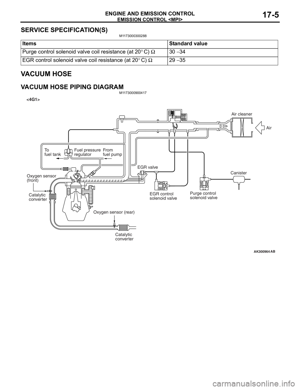
VACUUM HOSE PIPING DIAGRAMM1173000900417
AK300964
To
fuel tankFuel pressure
regulatorFrom
fuel pump
Catalytic
converter Catalytic
converter
Oxygen sensor
(front)
Oxygen sensor (rear)EGR valve
<4G1>
EGR control
solenoid valvePurge control
solenoid valve CanisterAir
AB
Air cleaner
Page 112 of 800
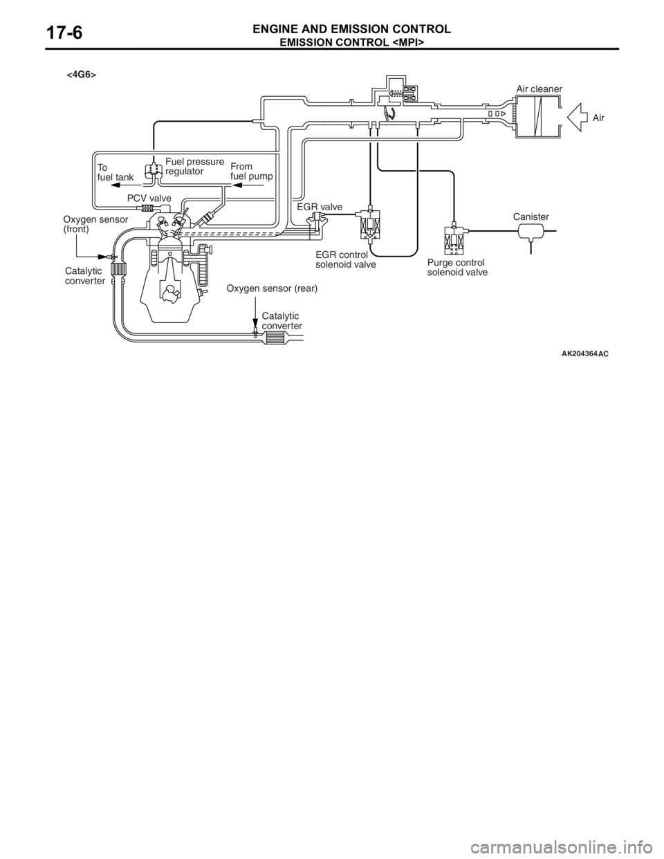
AK204364AC
Air cleaner
Air
Canister
Purge control
solenoid valve
EGR control
solenoid valve
EGR valve
From
fuel pump
To
fuel tank Fuel pressure
regulator
PCV valve
Oxygen sensor
(front)
Oxygen sensor (rear)
Catalytic
converter
Catalytic
converter
<4G6>
EMISSION CONTROL
ENGINE AND E M ISSION CON T ROL17-6
Page 113 of 800
EMISSION CONTROL
ENGINE AND EMISSION CONTROL17-7
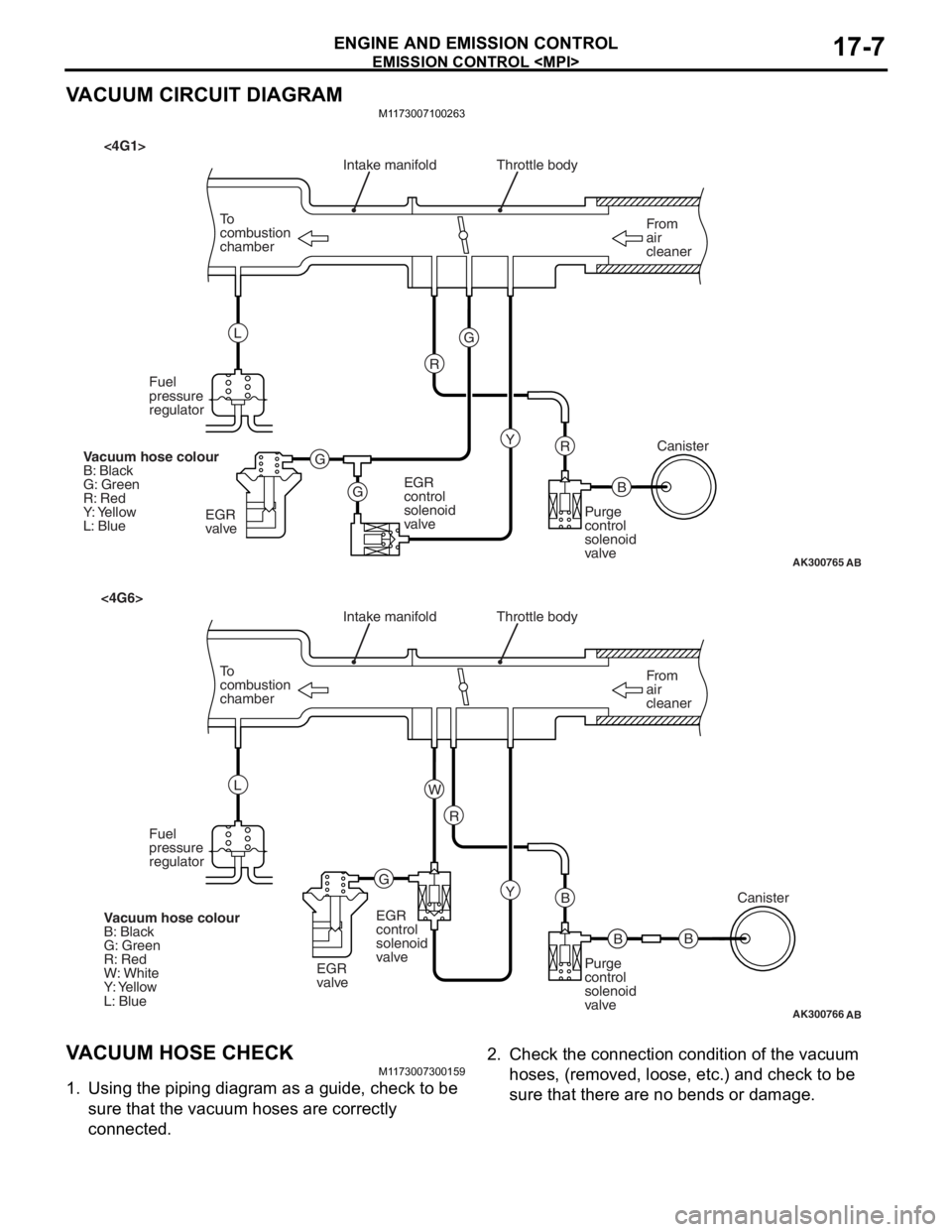
VACUUM CIRCUIT DIAGRAM
M1173007100263
AK300765
From
air
cleaner
To
combustion
chamber Throttle body
B
R
AB
Intake manifold
Y
G
G G R
L
Fuel
pressure
regulator
EGR
valve EGR
control
solenoid
valve
Purge
control
solenoid
valveCanister
Vacuum hose colour
B: Black
G: Green
R: Red
Y: Yellow
L: Blue
<4G1>
AK300766
From
air
cleaner
To
combustion
chamber Throttle body
B
B
AB
Intake manifold
Y
R
G W
L
Fuel
pressure
regulator
EGR
valveEGR
control
solenoid
valve
Purge
control
solenoid
valveCanister
Vacuum hose colour
B: Black
G: Green
R: Red
W: White
Y: Yellow
L: Blue
<4G6>
B
V ACUUM HOSE CHECK
M1 173 0073 0015 9
1.Using th e pip i ng d i agra m as a gu ide, check to be
sure th at the vacuum h o ses are correctly
connected.
2. Check t he co nnection cond itio n of th e vacuum
ho s e s, (re mo v e d, l o os e , et c . ) an d c h e c k t o b e
sure th at there are no bends or da mage .
Page 118 of 800
Battery voltageNormal condition
AppliedVacuum leaks
Not appliedVacuum maintained
EMISSION CONTROL
ENGINE AND EMISSION CONTROL17-12
5. Measure the resistance between the terminals of the solenoid valve.
Standard value: 30 − 34 Ω (at 20°C)
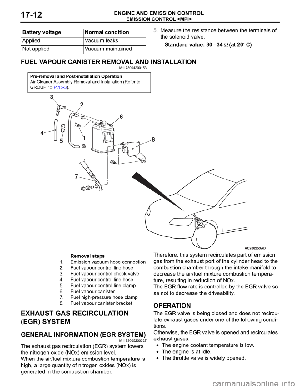
FUEL VAPOUR CANISTER RE MOVAL AND INSTALLATION
M1173004200153
Pre-removal and Post-installation Operation
Air Cleaner Assembly Removal and Installation (Refer to
GROUP 15
P.15-3).
AC208253
1
2
3
4 5 6
7 8
AD
Removal steps
1.Emission vacuum hose connection
2.Fuel vapour control line hose
3.Fuel vapour control check valve
4.Fuel vapour control line hose
5.Fuel vapour control line clamp
6.Fuel vapour canister
7.Fuel high-pressure hose clamp
8.Fuel vapour canister bracket
EXHAUST GAS RECIRCULA
T ION
(EGR) SYSTEM
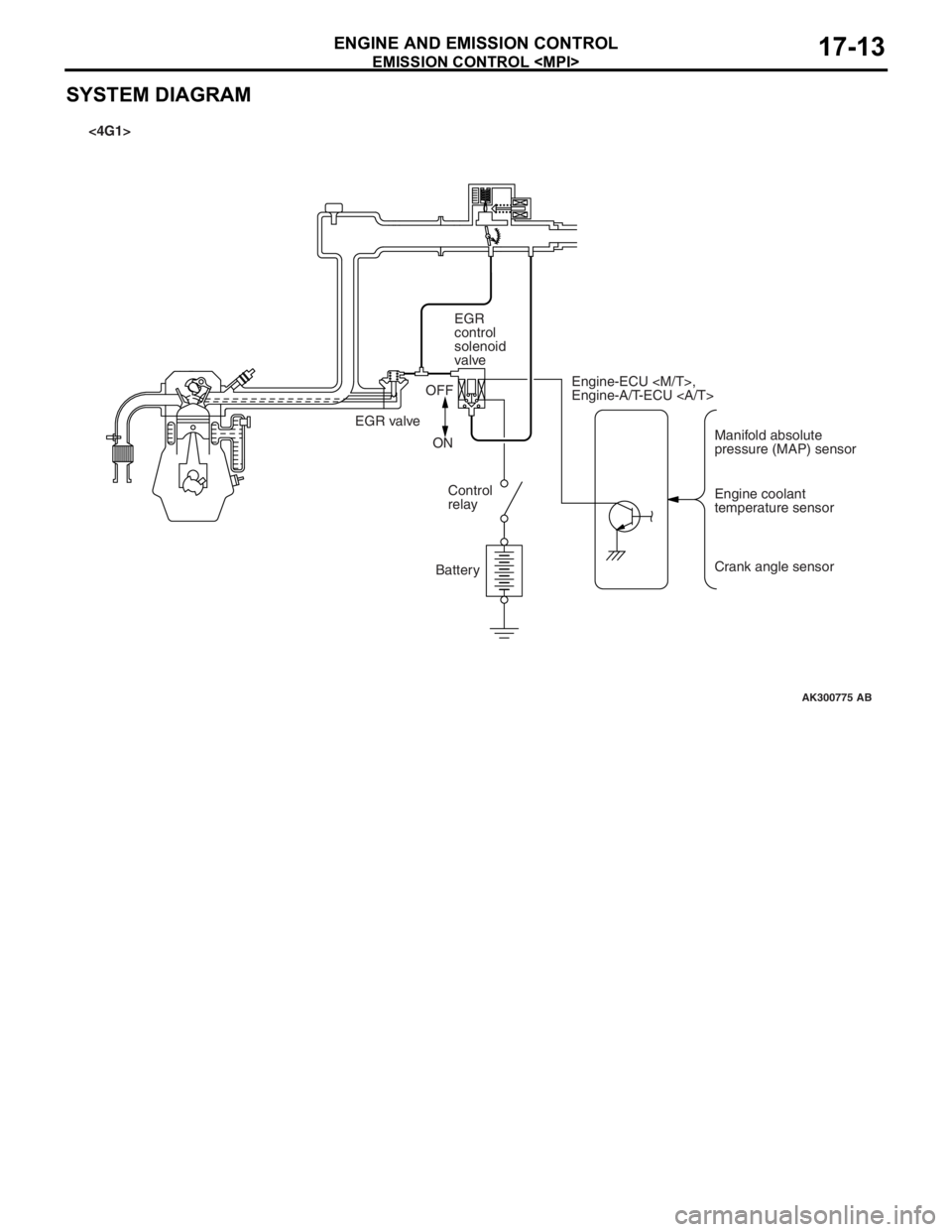
GENERAL INFORMAT ION (EGR SYSTEM)
M1173 0052 0032 7
The exhaust gas recircu l atio n (EGR) system lowers
the nitrogen
oxide (NOx) emission level.
When the air/fuel mixture combus tio n temp erature is
high,
a larg e qua ntity of nitrogen oxides (NOx) is
generat
ed in the comb ustion chamb e r .
Therefor e, this syst em re circulat es p a rt o f emission
gas fro
m the e x ha ust po rt of the cylinder h ead to th e
combust
i on chamber thro ugh th e int a ke ma nifold to
decre
ase the air/fuel mixture combust i on te mpera
-
ture, resulting in redu ctio n of NOx.
The EGR flow rate is cont rolle d by the EGR valve so
as no
t to de crease the driveability .
OPERAT ION
The EGR valve is being clos ed an d does not re circu-
late ex hau st ga ses unde r one o f the fo llo wing condi-
tions.
Otherwise, th e EGR va lve is opene d an d recircul ates
exha
ust g a ses.
•The engine coolan t temperature is low .
•The engine is at idle.
•The throttle va lve is widely ope ned.
Page 119 of 800
EMISSION CONTROL
ENGINE AND EMISSION CONTROL17-13
SYSTEM DIAGRAM
AK300775
Manifold absolute
pressure (MAP) sensor
Engine-ECU
Engine-A/T-ECU
Engine coolant
temperature sensor
Crank angle sensor
EGR
control
solenoid
valve
EGR valve OFF
ON Control
relay
Battery
AB
<4G1>