valve MITSUBISHI LANCER 2006 Workshop Manual
[x] Cancel search | Manufacturer: MITSUBISHI, Model Year: 2006, Model line: LANCER, Model: MITSUBISHI LANCER 2006Pages: 800, PDF Size: 45.03 MB
Page 15 of 800
14-1
GROUP 14
ENGINE COOLING
CONTENTS
GENERAL INFORMATION . . . . . . . .14-2
SERVICE SPECIFICATIONS . . . . . . .14-2
LUBRICANT . . . . . . . . . . . . . . . . . . . .14-3
SEALANTS . . . . . . . . . . . . . . . . . . . .14-3
SPECIAL TOOLS . . . . . . . . . . . . . . . .14-3
TROUBLESHOOTING . . . . . . . . . . . .14-5
INSPECTION CHART FOR TROUBLE
SYMPTOMS . . . . . . . . . . . . . . . . . . . . . . . . 14-5
INSPECTION PROCEDURE FOR
TROUBLE SYMPTOMS . . . . . . . . . . . . . . . 14-6
ON-VEHICLE SERVICE . . . . . . . . . . .14-21
ENGINE COOLANT LEAK CHECK . . . . . . 14-21
RADIATOR CAP VALVE OPENING
PRESSURE CHECK . . . . . . . . . . . . . . . . . . 14-21
ENGINE COOLANT REPLACEMENT . . . . 14-21
CONCENTRATION MEASUREMENT . . . . 14-22
COOLING FAN MOTOR DRIVE
CONTROL UNIT CHECK . . . . . . . . . . . . . . 14-22
FAN CONTROL RELAY CONTINUITY
CHECK . . . . . . . . . . . . . . . . . . . . . . . . . . . . 14-23
COOLING FAN MOTOR CHECK . . . . . . . . 14-24
THERMOSTAT . . . . . . . . . . . . . . . . . .14-24
REMOVAL AND INSTALLATION . . . . . . . . 14-24
INSPECTION. . . . . . . . . . . . . . . . . . . . . . . . 14-26
WATER PUMP . . . . . . . . . . . . . . . . . .14-27
REMOVAL AND INSTALLATION <4G1> . . 14-27
REMOVAL AND INSTALLATION <4G6> . . 14-28
WATER HOSE AND WATER PIPE . .14-29
REMOVAL AND INSTALLATION <4G1> . . 14-29
REMOVAL AND INSTALLATION <4G6> . . 14-31
INSPECTION. . . . . . . . . . . . . . . . . . . . . . . . 14-32
RADIATOR . . . . . . . . . . . . . . . . . . . . .14-33
REMOVAL AND INSTALLATION <4G1> . . 14-33
REMOVAL AND INSTALLATION <4G6> . . 14-35
Page 16 of 800

GENERAL INFORMATION
ENGINE COOLING14-2
GENERAL INFORMATION
M1141000100371
The cooling system is designed to keep every part of
the engine at appropriate temperature in whatever
condition the engine may be operated. The cooling
method is of the water-cooled, pressure forced circu
-
lation type in which the water pump pressurizes cool-
ant and circulates it throughout the engine. If the
coolant temperature exceeds the prescribed temper
-
ature, the thermostat opens to circulate the coolant
through the radiator as well so that the heat
absorbed by the coolant may be radiated into the air.
The water pump is of the centrifugal type and is
driven by the alternator drive belt from the crank
-
shaft. The radiator is the corrugated fin, down flow
type.
ItemSpecification
RadiatorPerformance kJ/h4G13Standard vehicles137,720
Vehicles with capacity up radiator
(option)161,288
4G18Standard vehicles161,288
Vehicles with capacity up radiator
(option)181,800
4G63181,800
A/T oil coolerPerformance kJ/h5,651
SERVICE SPECIFICATIONS
M1141000300687
ItemStandard valueLimit
Fan controller VA/C OFF1 or less-
A/C ONRepeat
8.2 ± 0.7
System voltage ± 2.6
-
High-pressure valve opening pressure of radiator cap kPa93 − 123Minimum 83
Range of coolant antifreeze concentration of radiator %30 − 60-
ThermostatValve opening temperature of
thermostat
°C
4G188 ± 1.5-
4G682 ± 1.5-
Full-opening temperature of
thermostat
°C
4G1100-
4G695-
Valve lift mm8.5 or more-
Page 35 of 800
ON-VEHICLE SERVICE
ENGINE COOLING14-21
ON-VEHICLE SERVICE
ENGINE COOLANT LEAK CHECKM1141001000300
WARNING
When pressure testing the cooling system,
slowly release cooling system pressure to
avoid getting burned by hot coolant.
CAUTION
•Be sure to completely clean away any mois-
ture from the places checked.
•When the tester is taken out, be careful not to
spill any coolant.
•
ACX01844
Cap adapter
Adapter
AC
Be careful when installing and removing the
tester and when testing not to deform the
filler neck of the radiator.
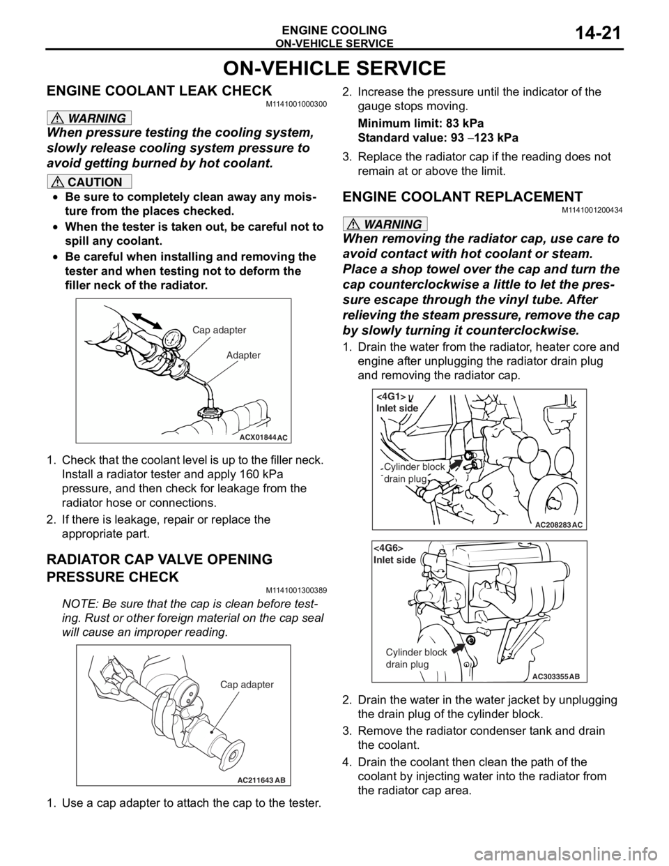
1. Check that the coolant leve l is up to the filler neck.
Install a radiator tester and apply 160 kPa
pressure, and then check for leakage from the
radiator hose or connections.
2. If there is leakage, repair or replace the
appropriate part.
RADIATOR CAP VALVE OPENING
PRESSURE CHECK
M1141001300389
NOTE: Be sure that the cap is clean before test-
ing. Rust or other foreign material on the cap seal
will cause an improper reading.
AC211643AB
Cap adapter
1. Use a cap adapter to attach the cap to the tester.
2. Increase the pressure until the indicator of the gauge stops moving.
Minimum limit: 83 kPa
Standard value: 93 − 123 kPa
3. Replace the radiator cap if the reading does not remain at or above the limit.
ENGINE COOLANT REPLACEMENT
M1141001200434
WARNING
When removing the radiator cap, use care to
avoid contact with hot coolant or steam.
Place a shop towel over the cap and turn the
cap counterclockwise a little to let the pres
-
sure escape through the vinyl tube. After
relieving the steam pres sure, remove the cap
by slowly turning it counterclockwise.
1. Drain the water from the radiator, heater core and
engine after unplugging the radiator drain plug
and removing the radiator cap.
AC208283AC
Cylinder block
drain plug
<4G1>
Inlet side
AC303355
<4G6>
Inlet side
Cylinder block
drain plug
AB
2. Drain the water in the water jacket by unplugging the drain plug of the cylinder block.
3. Remove the radiator condenser tank and drain
the coolant.
4. Drain the coolant then clean the path of the coolant by injecting water into the radiator from
the radiator cap area.
Page 39 of 800
AC301429
1
2 36
7
13 ± 2 N·m
AD
5
<4G6>
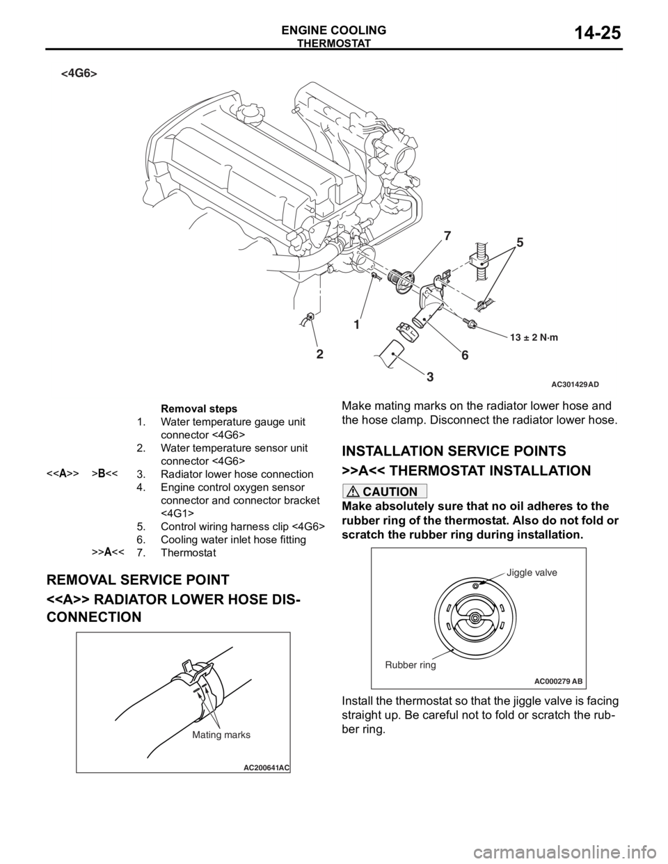
Removal steps
1.Water temperature gauge unit
connector <4G6>
2.Water temperature sensor unit
connector <4G6>
<>>B<<3.Radiator lower hose connection
4.Engine control oxygen sensor
connector and connector bracket
<4G1>
5.Control wiring harness clip <4G6>
6.Cooling water inlet hose fitting
>>A<<7.Thermostat
THERMOST
A T
ENGINE COOLING14-25
REMOV A L SER V ICE POINT
<> RADIAT OR LOW E R HOSE DIS-
CONNECTION
AC200641AC
Mating marks
Make mating marks on the rad i ator lower ho se an d
the hose clamp. Disconn
ect t he radiator lower hose.
INSTALLA T ION SER VICE POINTS
>>A<< THERMOSTA T INST ALLA TION
CAUTION
Make absolutely sure that no oil adheres to the
rubber ring of the thermostat. Also do not fold or
scratch the rubber ring during installation.
AC000279
Jiggle valve
Rubber ring
AB
Install the thermostat so that the jiggle valve is facing
straight up. Be careful not to fold or scratch the rub
-
ber ring.
Page 40 of 800
THERMOSTAT
ENGINE COOLING14-26
>>B<< RADIATOR LOWER HOSE
CONNECTION
AC200642
Mating marks
Projection
Cooling water inlet
hose fitting
AH
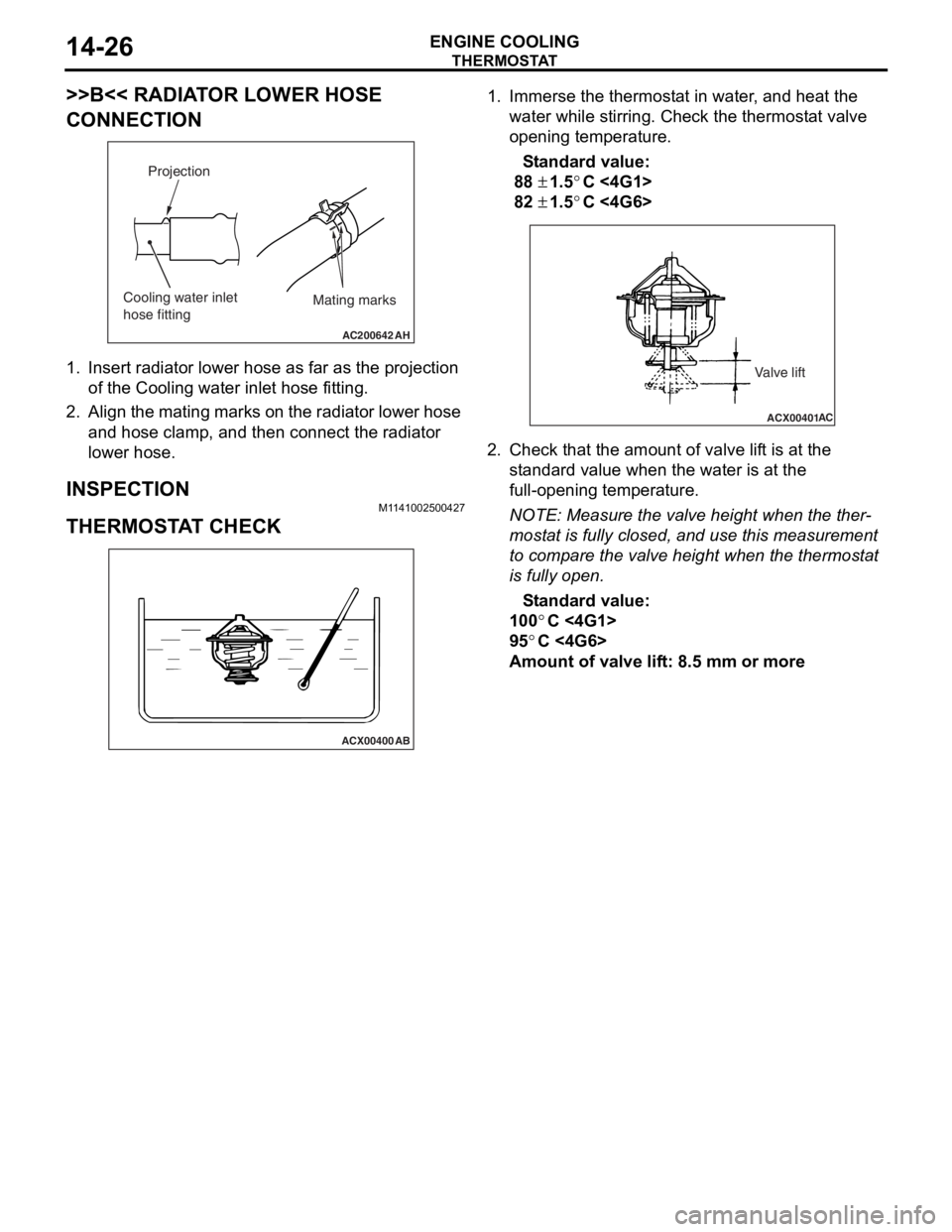
1.In sert ra diato r lower h o se a s fa r as th e projection
of the Cooling wa ter inlet ho se fitting .
2.Align the mating marks on the radiator lower hose
an d hose clamp, and then connect the radia t or
lower hose.
INSPECTION
M1 141 0025 0042 7
THERMOSTA T CHECK
ACX00400
AB
1.Imme rse th e thermost at in water , and h eat the
wate r wh ile stirring. Ch eck the th ermost a t va lve
o penin g temperatu r e.
St andard va lue:
88 ± 1.5°C <4G1 >
82 ± 1.5°C <4G6 >
ACX00401 AC
Valve lift
2.
Check t hat the amo unt of valve lif t is at the
st a ndard valu e when th e water is at the
fu ll-o penin g temperatu r e.
NOTE: Meas ure the valve height when the the r-
mostat is fu lly closed , and use t h is measurement
to
comp are the valve h e ight wh en the thermost at
is fully open.
St andard va lue:
100°C <4G1>
95°C <4G6>
Amou nt of val ve lif t: 8 . 5 mm or more
Page 41 of 800
WATE R P U M P
ENGINE COOLING14-27
WAT E R P U M P
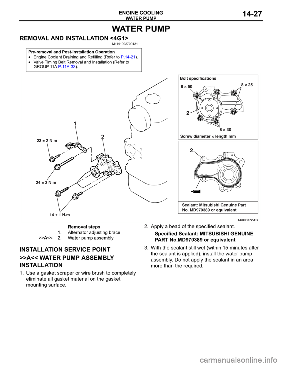
REMOVAL AND INSTALLATION <4G1>M1141002700421
Pre-removal and Post-installation Operation
•Engine Coolant Draining and Refilling (Refer to P.14-21).
•Valve Timing Belt Removal and Installation (Refer to
GROUP 11A P.11A-33).
AC303372
24 ± 3 N·m23 ± 2 N·m
14 ± 1 N·m
1 2
Bolt specifications
Screw diameter × length mm 8 × 50
8 × 308 × 25
AB
2
2
Sealant: Mitsubishi Genuine Part
No. MD970389 or equivalent
Removal steps
1.Alternator adjusting brace
>>A<<2.Water pump assembly
INST ALLA T ION SER VICE POINT
>>A<< WA TER PUMP ASSEMBL Y
INST
ALLA TION
1.Use a gaske t scraper o r wire brush to complet e ly
eliminate all gasket material o n the g a sket
mounting surface.
2. App l y a bead of the specified sealan t.
Specified Sealant: MITSUBISHI GENUINE
P
ART No.MD970 389 or eq uivalen t
3.With the sea l ant still wet (within 1 5 minutes af ter
th e se alant is applied), inst all the wa ter pump
a sse mbly . Do not a pply the sealant in an are a
more th an the required.
Page 42 of 800
WATE R P U M P
ENGINE COOLING14-28
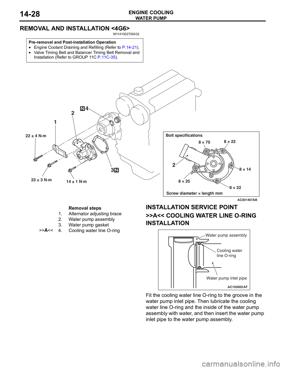
REMOVAL AND INSTALLATION <4G6>
M1141002700432
Pre-removal and Post-installation Operation
•Engine Coolant Draining and Refilling (Refer to P.14-21).
•Valve Timing Belt and Balancer Timing Belt Removal and
Installation (Refer to GROUP 11C
P.11C-35).
AC301467
22 ± 4 N·m23 ± 3 N·m 14 ± 1 N·m
12
3
4
N
N
Bolt specifications
Screw diameter × length mm
8 × 70 8 × 22
8 × 14
8 × 22
8 × 25
2
AB
Removal steps
1.Alternator adjusting brace
2.Water pump assembly
3.Water pump gasket
>>A<<4.Cooling water line O-ring
INST
ALLA T ION SER VICE POINT
>>A<< COOLING WA TER LINE O-RING
INST
ALLA TION
AC103005
Water pump assembly
Cooling water
line O-ring
Water pump inlet pipe
AF
Fit the coo ling water line O-ring to the groove in the
wa
ter pump in let p i pe. T hen lubricate th e co olin g
wa
ter line O-ring and the inside of the wat e r pump
assembly with wa
ter , and then insert the wa ter pu mp
inle
t pip e to the water pu mp asse mbly .
Page 55 of 800
INLET MANIFOLD
INTAKE AND EXHAUST15-5
INLET MANIFOLD
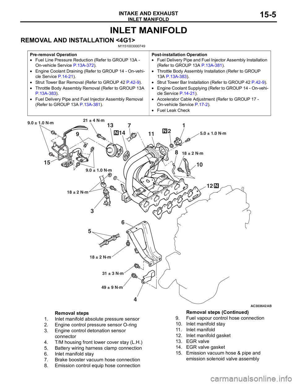
REMOVAL AND INSTALLATION <4G1>M1151003000749
Pre-removal Operation
•Fuel Line Pressure Reduction (Refer to GROUP 13A -
On-vehicle Service
P.13A-372).
•Engine Coolant Draining (Refer to GROUP 14 - On-vehi-
cle Service P.14-21).
•Strut Tower Bar Removal (Refer to GROUP 42 P.42-9).
•Throttle Body Assembly Re moval (Refer to GROUP 13A
P.13A-383).
•Fuel Delivery Pipe and Fuel Injector Assembly Removal
(Refer to GROUP 13A
P.13A-381).
Post-installation Operation
•Fuel Delivery Pipe and Fuel Injector Assembly Installation
(Refer to GROUP 13A
P.13A-381).
•Throttle Body Assembly Inst allation (Refer to GROUP
13A
P.13A-383).
•Strut Tower Bar Installati on (Refer to GROUP 42 P.42-9).
•Engine Coolant Supplying (Refer to GROUP 14 - On-vehi-
cle Service P.14-21).
•Accelerator Cable Adjustment (Refer to GROUP 17 -
On-vehicle Service
P.17-2).
•Fuel Leak Check
AC303642AB
15
36
5
4 12
10
7
1
2
11
9 13
14
21 ± 4 N·m
9.0 ± 1.0 N·m
9.0 ± 1.0 N·m
18 ± 2 N·m
18 ± 2 N·m 18 ± 2 N·m
5.0 ± 1.0 N·m
31 ± 3 N·m
49 ± 9 N·m
N
N
N
8
Removal steps
1.Inlet manifold absolute pressure sensor
2.Engine control pressure sensor O-ring
3.Engine control detonation sensor
connector
4.T/M housing front lower cover stay (L.H.)
5.Battery wiring harness clamp connection
6.Inlet manifold stay
7.Brake booster vacuum hose connection
8.Emission control equip hose connection
9.Fuel vapour control hose connection
10.Inlet manifold stay
11 .Inlet manifold
12.Inlet manifold gasket
13.EGR valve
14.EGR valve gasket
15.Emission vacuum hose & pipe and
emission solenoid valve assembly
Removal steps (Continued)
Page 57 of 800
EXHAUST MANIFOLD
INTAKE AND EXHAUST15-7
INSPECTION
M1151003100616
Check the following points; replace the part if a prob-
lem is found.
Inlet Manifold Check
1. Check for damage or cracking of any part.
2. Clogging of the negative pressure (vacuum) outlet port, or clogging of the exhaust gas recirculation
passages.
3. Using a straight edge and feeler gauge, check for distortion of the cylinder head installation surface.
Standard value: 0.15 mm or less
Limit: 0.20 mm
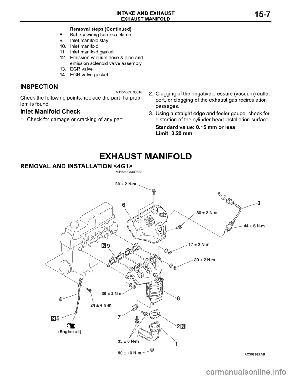
EXHAUST MANIFOLD
REMOVAL AND INSTALLATION <4G1>
M1151003300568
AC30366250 ± 10 N·m
24 ± 4 N·m
35 ± 6 N·m 17 ± 2 N·m
30 ± 2 N·m
N
3
7 12
4
N
6
8
44 ± 5 N·m
AB
9
5N
30 ± 2 N·m
30 ± 2 N·m
30 ± 2 N·m
(Engine oil)
8.Battery wirin g ha rne s s clamp
9.Inlet manifold st ay
10.Inlet manifold
11.Inlet manifold gask et
12.Emission vacuu m hose & pipe and
emis
sion s o lenoid valve assembly
13.EGR v a lve
14.EGR v a lve gasket
Remo va l st ep s ( C o n t in u e d)
Page 103 of 800
IGNITION SYSTEM
ENGINE ELECTRICAL16-41
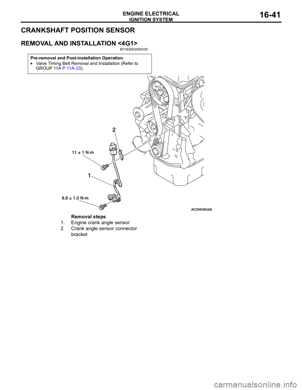
CRANKSHAFT POSITION SENSOR
REMOVAL AND INSTALLATION <4G1>
M1163003500439
Pre-removal and Post-installation Operation
•Valve Timing Belt Removal and Installation (Refer to
GROUP 11A P.11A-33).
AC208380AB
12
11 ± 1 N·m
8.8 ± 1.0 N·m
Removal steps
1.Engine crank angle sensor
2.Crank angle sensor connector
bracket