MITSUBISHI LANCER 2014 8.G Owners Manual
Manufacturer: MITSUBISHI, Model Year: 2014, Model line: LANCER, Model: MITSUBISHI LANCER 2014 8.GPages: 434, PDF Size: 57.5 MB
Page 381 of 434
Tires 9-22 Vehicle care and maintenance
9
Keep your tires inflated to the recom- mended pressures. (See the tire and load- ing information placard attached to the sill of the driver’s door.) Stay within the recommended load limits. Make sure that the weight of any load in your vehicle is evenly distributed. Drive at safe speeds. After filling your tires to the correct pres- sure, check them for damage and airleaks. Be sure to reinstall the caps on thevalve stems.
N00939600368
N00939700154
The following maintenance steps are recom- mended: Check tire pressures regularly.
Have regular maintenance done on the wheel balance and front and rear suspen- sion alignment. Rotate your tires regularly as described in the “Tire rotation” section on page 9-23.
N00939800214
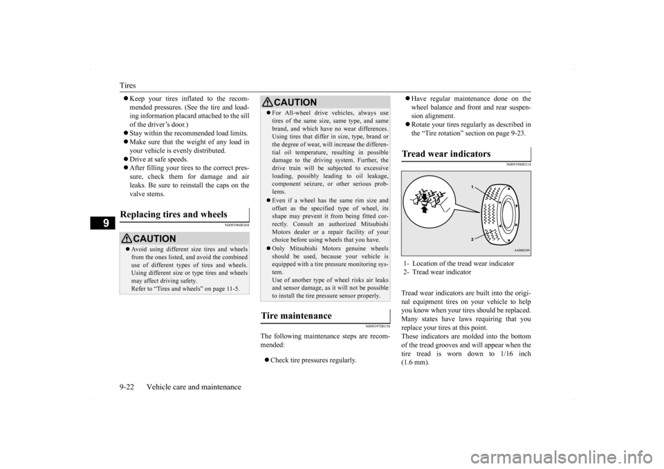
Tread wear indicators are built into the origi- nal equipment tires on your vehicle to help you know when your tires should be replaced.Many states have laws requiring that you replace your tires at this point. These indicators are molded into the bottomof the tread grooves and will appear when the tire tread is worn down to 1/16 inch (1.6 mm).
Replacing tires and wheels
CAUTION Avoid using different size tires and wheels from the ones listed, and avoid the combined use of different types of tires and wheels.Using different size or type tires and wheels may affect driving safety. Refer to “Tires and wheels” on page 11-5.
For All-wheel drive vehicles, always use tires of the same size, same type, and same brand, and which have no wear differences. Using tires that differ in size, type, brand or the degree of wear, will increase the differen-tial oil temperature, resulting in possible damage to the driving system. Further, the drive train will be subjected to excessiveloading, possibly leading to oil leakage, component seizure, or other serious prob- lems. Even if a wheel has the same rim size and offset as the specified type of wheel, itsshape may prevent it from being fitted cor- rectly. Consult an authorized Mitsubishi Motors dealer or a repair facility of yourchoice before using wheels that you have. Only Mitsubishi Motors genuine wheels should be used, because your vehicle is equipped with a tire pressure monitoring sys- tem.Use of another type of wheel risks air leaks and sensor damage, as it will not be possible to install the tire pressure sensor properly.
Tire maintenance
CAUTION
Tr e a d w e a r i n d i c a t o r s 1- Location of the tread wear indicator 2- Tread wear indicator
Page 382 of 434
Tires
Vehicle care and maintenance 9-23
9
When the bands appear next to one another in two or more places, replace your tires.
N00939900390
To even out the wear on your tires and makethem last longer, Mitsubishi Motors Corpora- tion recommends that you rotate your tires at the mileage listed in the “WARRANTY ANDMAINTENANCE MANUAL”. However, the timing for tire rotation may vary according to your vehicle condition,road surface conditions, and your own per- sonal driving habits. Any time you notice unusual wear, rotate your tires as soon as pos-sible. When rotating tires, check for uneven wear, damage, and wheel alignment. Abnormal wear is usually caused by a wrong tire pres-sure, wheels that are not aligned properly, wheels that are out-of-balance, or severe braking.Check with an authorized Mitsubishi Motors dealer or a repair facility of your choice to find out the reason for uneven tread wear.
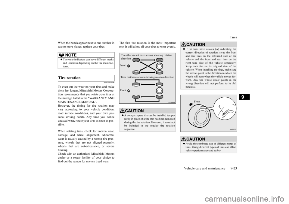
The first tire rotation is the most important one. It will allow all your tires to wear evenly.
NOTE
Tire wear indicators can have different marks and locations depending on the tire manufac- turer.
Tire rotation
CAUTION A compact spare tire can be installed tempo- rarily in place of a tire that has been removedduring the tire rotation. However, it must not be included in the regular tire rotation sequence.Tires that do not have
arrows showing rotation
direction Front Tires that have arrows showing rotation direction Front
CAUTION If the tires have arrows (A) indicating the correct direction of rotation, swap the front and rear tires on the left-hand side of the vehicle and the front and rear tires on the right-hand side of the vehicle separately.Keep each tire on its original side of the vehicle. When installing the tires, make sure the arrows point in the
direction in which the
wheels will turn when the vehicle moves for- ward. Any tire whose arrow points in the wrong direction will not perform to its fullpotential.CAUTION Avoid the combined use of different types of tires. Using different types of tires can affectvehicle performance and safety.
Front
Page 383 of 434
Clutch pedal free play (if so equipped) 9-24 Vehicle care and maintenance
9
N00940000359
In some areas of the country, snow tires are required for winter driving. If snow tires arerequired in your area, you must choose snow tires of the same size and type as the original tires provided with your vehicle. Snow tiresshould also be installed on all four wheels. Otherwise your safety and vehicle handling can be reduced.Even where laws may permit it, snow tiresshould not be operated at sustained speeds over 75 mph (120 km/h).
N00940100129 N00940201097
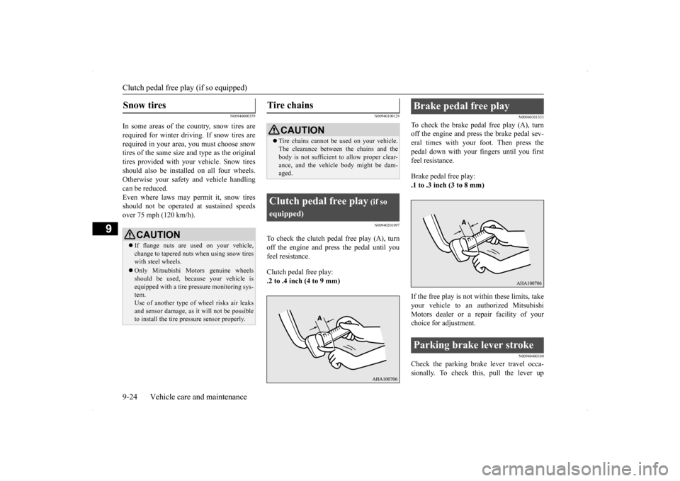
To check the clutch pedal free play (A), turn off the engine and press the pedal until you feel resistance. Clutch pedal free play: .2 to .4 inch (4 to 9 mm)
N00940301333
To check the brake pedal free play (A), turnoff the engine and press the brake pedal sev-eral times with your foot. Then press the pedal down with your fingers until you first feel resistance. Brake pedal free play: .1 to .3 inch (3 to 8 mm) If the free play is not within these limits, take your vehicle to an authorized Mitsubishi Motors dealer or a repair facility of your choice for adjustment.
N00940400180
Check the parking brake lever travel occa-sionally. To check this, pull the lever up
Snow tires
CAUTION If flange nuts are used on your vehicle, change to tapered nuts when using snow tireswith steel wheels. Only Mitsubishi Motors genuine wheels should be used, because your vehicle is equipped with a tire pressure monitoring sys- tem.Use of another type of wheel risks air leaks and sensor damage, as it will not be possible to install the tire pressure sensor properly.
Tire chains
CAUTION Tire chains cannot be used on your vehicle. The clearance between the chains and the body is not sufficient to allow proper clear- ance, and the vehicle body might be dam-aged.
Clutch pedal free play
(if so
equipped)
Brake pedal free play Parking brake lever stroke
Page 384 of 434
Parking brake break-in
Vehicle care and maintenance 9-25
9
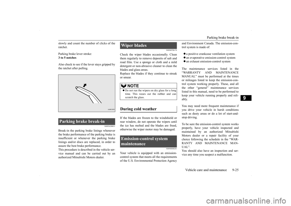
slowly and count the number of clicks of the ratchet. Parking brake lever stroke: 3 to 5 notches Also check to see if the lever stays gripped by the ratchet after pulling.
N00936200031
Break-in the parking brake linings wheneverthe brake performance of the parking brake is insufficient or whenever the parking brake linings and/or discs are replaced, in order toassure the best brake performance. This procedure is described in the vehicle ser- vice manual and can be carried out by anauthorized Mitsubishi Motors dealer.
N00940700170
Check the wiper blades occasionally. Cleanthem regularly to remove deposits of salt androad film. Use a sponge or cloth and a mild detergent or non-abrasive cleaner to clean the blades and glass areas.Replace the blades if they continue to streak or smear. If the blades are frozen to the windshield or rear window, do not operate the wipers until the ice has melted and the blades are freed,otherwise the wiper motor may be damaged.
N00940800201
Your vehicle is equipped with an emission-control system that meets all the requirements of the U.S. Environmental Protection Agency
and Environment Canada. The emission-con- trol system is made of: a positive crankcase ventilation system an evaporative emission-control system an exhaust emission-control system
The maintenance services listed in the “WARRANTY AND MAINTENANCE MANUAL” must be performed at the times or mileages listed to keep the emission-con-trol system working properly. These, and allthe other “general” maintenance services listed in this manual, need to be performed to keep your vehicle running properly and reli-ably. You may need more frequent maintenance if you drive your vehicle in harsh conditions such as dusty areas or
do a lot of start-and-
stop driving. To be sure the emission-control system works properly, have your vehicle inspected and maintained by an authorized MitsubishiMotors dealer or a repair facility of your choice following the schedule in the “WAR- RANTY AND MAINTENANCE MAN-UAL”. You should also have an inspection and ser- vice any time you suspect a malfunction.
Parking brake break-in
Wiper blades
NOTE
Do not run the wipers on dry glass for a long time. This wears out the rubber and can scratch the glass.
During cold weather Emission-control system maintenance
Page 385 of 434
General maintenance 9-26 Vehicle care and maintenance
9
N00940900215
Spark plugs must fire properly for good engine performance and emission-control.Do not reuse them by cleaning or regapping. Change them at the mileage listed in the “WARRANTY AND MAINTENANCEMANUAL”.
N00941000037
Check the hose surfaces for any heat andmechanical damage, hard and brittle rubber,cracking, tears, cuts and abrasions. Pay spe- cial attention to the hoses closest to high heat sources such as the exhaust manifold. Checkall the hose connections, such as clamps and couplings, to make sure they are secure and that there are no leaks. If you see any wear ordamage, replace the hoses immediately.
N00950100050
Have the valve clearance checked at anauthorized Mitsubishi Motors dealer at themileage specified in the “WARRANTY AND MAINTENANCE MANUAL”. If the engine sounds abnormally loud, haveadjustments made by an authorized Mitsubishi Motors dealer.
N00941300085
Check these regularly for damage or leaks in the fuel lines and connections. Check the fuel tank filler cap for damage or looseness. Pay special attention to the fuel lines closest to
high heat sources such as the exhaust mani- fold.
N00941400116
If the fuel-vapor vent line is clogged or dam- aged, the fuel-vapor mixture will escape, pol- luting the air.Have the system checked at an authorized Mitsubishi Motors dealer at the mileage spec- ified in the “WARRANTY AND MAINTE-NANCE MANUAL”.
N00941500159
The next pages list the maintenance servicerecommended by Mitsubishi Motors Corpo- ration. In addition to the general maintenance that needs to be performed at the times listed,
NOTE
To meet government regulations and pro- mote cleaner air, your vehicle is equipped with an onboard diagnostic system (OBD). The engine electronic control module that controls OBD functions stores various data(especially about the exhaust emissions). This data will be erased if the battery cable is disconnected, which could make a rapiddiagnosis difficult. Do not disconnect the battery cable when the engine malfunction indicator (“SERVICE ENGINE SOON” or“Check engine light”) is on.
Spark plugs
NOTE
Use the spark plugs listed under “Engine specifications” on page 11-5 or plugs that are exactly the same. Other plugs could causeengine damage, performance problems or radio noise.
Fuel hoses Intake valve clearance Fuel system (tank, pipe line and connection, and fuel tank filler cap)
WA R N I N G If you see a fuel leak or if you smell fuel, do not run the engine. Any spark (includ- ing from the ignition), flame or smokingmaterial could cause an explosion or fire. Call an authorized Mitsubishi Motors dealer or a repair facility of your choicefor assistance.
Evaporative emission control system (except evaporative emission canister) General maintenance
Page 386 of 434
General maintenance
Vehicle care and maintenance 9-27
9
there are other parts which do not usually need regular maintenance. But, if any of these parts stops working prop- erly, your vehicle performance could suffer.Have these items checked if you notice a problem with them. See your authorized Mitsubishi Motors dealer for assistance, if you have any questions.
N00941600033
Good brakes are essen
tial to safe driving.
Check the brake pads and brake linings for wear and check the rear wheel cylinders for leaks. For good braking performance, replacethe brake pads with the
same type pads as the
originals.
N00941700047
Brake hoses and tubing should be checkedfor:
Severe surface cracking, scuffing or worn spots. If the fabric casing of the hose is showing through any cracks or worn spots in the rubber hose cover, the hose shouldbe replaced. The brakes can fail if the hose wears through. Improper installation may cause twisting, or wheel, tire or chassis interference.
N00941800077
Check the following parts for damage andgrease leaks: Ball joint boots of the front suspension and steering linkage Bellows on both ends of the drive shaft
N00942200108
The best way to keep carbon monoxide gas from entering inside your vehicle is to have the engine exhaust system properly serviced.
Have a competent mechanic inspect the com- plete exhaust system and nearby body areas for broken, damaged, deteriorated, or mispo- sitioned parts if you notice any of the follow-ing: A change in the sound of the exhaust sys- tem The smell of exhaust fumes inside the vehicle The underside or rear of the vehicle is damaged
Also check the exhaust system each time the vehicle is raised for lubrication, oil changes,or required service. Any open seams or loose connections could let dangerous exhaust fumes seep into the luggage compartment andpassenger compartments. Check for holes or exhaust gas leaks caused by corrosion or damage. Check the joints and connections for looseness or exhaust gas leaks. Check the rubber hangers and brackets for damage.
Disc brake pads, rear drum brake linings and rear wheel cylinders Brake hoses
Ball joint, steering linkage seals and drive shaft boots Exhaust system
WA R N I N G Carbon monoxide gas from your vehicle’s exhaust is poisonous. Breathing these fumes can cause unconsciousness or death.
Check for any of the following conditions:
Page 387 of 434
For cold and snowy weather 9-28 Vehicle care and maintenance
9
N00942500114
The hood lock release mechanism and hood safety catch should be checked, cleaned, and oiled when needed for easy movement and to stop rust and wear. Use Multipurpose GreaseNLGI Grade 2 sparingly for all sliding parts of the hood latch and release lever. Work the grease into the hood lock mechanism until allthe movable surfaces are covered.Also, put a light coat of the same grease on the safety catch wherever moving parts touch.
N00942600102
The ventilation slots in front of the wind-shield should be brushed clear after a heavy snowfall so that the operation of the heatingand ventilation systems will not be impaired. To prevent freezing of the weatherstripping on the doors, engine hood, etc., they should be treated with silicone grease.
It is a good idea to carry a shovel or a short- handled spade in the vehicle during the win- ter so that you can clear away snow if you getstranded. A small hand-brush for sweeping snow off the vehicle and a plastic scraper for the windshield, side and rear window are alsouseful.
N00942700259
The fusible links will melt
to prevent a fire if
a large current attempts to flow through cer-tain electrical systems. In case of a melted fusible link, see your authorized Mitsubishi Motors dealer or arepair facility of your choice for inspection and replacement. For the fusible links, please refer to “Fuseload capacities” on page 9-29.
N00942800801
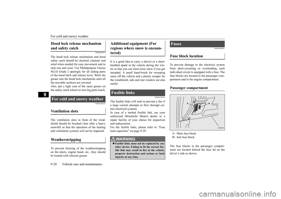
To prevent damage to the electrical systemfrom short-circuiting or overloading, eachindividual circuit is equipped with a fuse. The fuse blocks are located in the passenger com- partment and in the engine compartment. The fuse blocks in the passenger compart- ment are located behind the fuse lid on the driver’s side as shown.
Hood lock release mechanism and safety catch For cold and snowy weather Ventilation slots Weatherstripping
Additional equipment (For regions where snow is encoun- tered) Fusible links
WA R N I N G Fusible links must not be replaced by any other device. Failing to fit the correct fus- ible link may result in fire in the vehicle,property destruction and serious or fatal injuries at any time.
Fuses Fuse block location Passenger compartment A- Main fuse block B- Sub fuse block
Page 388 of 434
Fuses
Vehicle care and maintenance 9-29
9
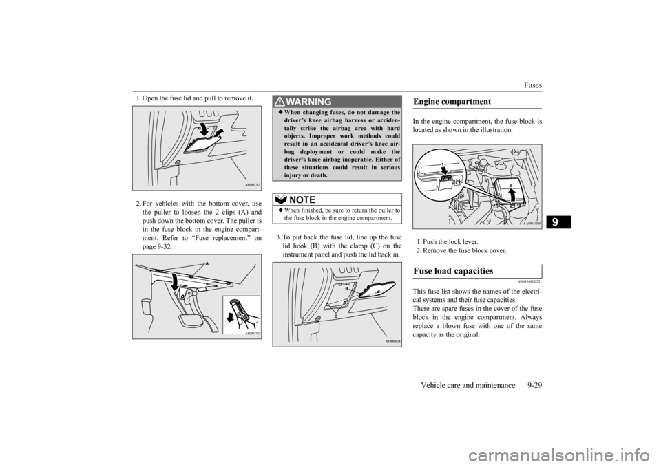
1. Open the fuse lid and pull to remove it. 2. For vehicles with the bottom cover, use the puller to loosen the 2 clips (A) and push down the bottom cover. The puller is in the fuse block in the engine compart-ment. Refer to “Fuse replacement” on page 9-32.
3. To put back the fuse lid, line up the fuse lid hook (B) with the clamp (C) on theinstrument panel and push the lid back in.
In the engine compartment, the fuse block is located as shown in the illustration. 1. Push the lock lever. 2. Remove the fuse block cover.
N00954800231
This fuse list shows the names of the electri- cal systems and their fuse capacities. There are spare fuses in the cover of the fuseblock in the engine compartment. Always replace a blown fuse with one of the same capacity as the original.
WA R N I N G When changing fuses, do not damage the driver’s knee airbag harness or acciden- tally strike the airbag area with hard objects. Improper work methods could result in an accidental driver’s knee air-bag deployment or could make the driver’s knee airbag inoperable. Either of these situations could result in seriousinjury or death.NOTE
When finished, be sure to return the puller to the fuse block in the engine compartment.
Engine compartment Fuse load capacities
Page 389 of 434
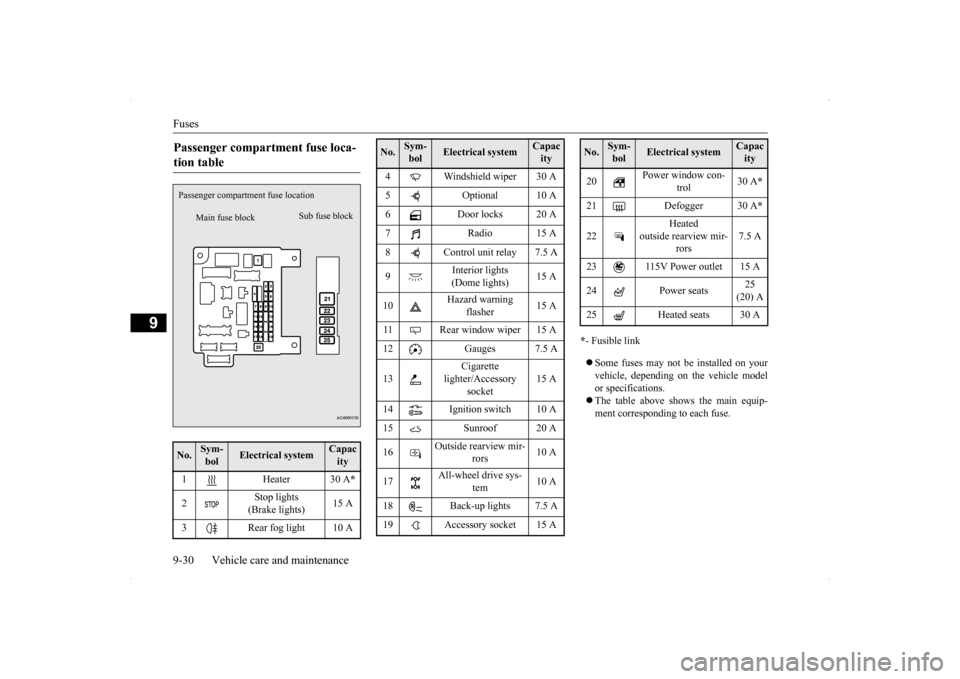
Fuses 9-30 Vehicle care and maintenance
9
* - Fusible link Some fuses may not be installed on your vehicle, depending on the vehicle model or specifications. The table above shows the main equip- ment corresponding to each fuse.
Passenger compartment fuse loca- tion table No.
Sym- bol
Electrical system
Capacity
1 Heater 30 A
*
2
Stop lights (Brake lights)
15 A
3 Rear fog light 10 A
Main fuse block
Sub fuse block
Passenger compartme
nt fuse location
4 Windshield wiper 30 A 5 Optional 10 A 6 Door locks 20 A 7 Radio 15 A8 Control unit relay 7.5 A 9
Interior lights (Dome lights)
15 A
10
Hazard warning
flasher
15 A
11 Rear window wiper 15 A 12 Gauges 7.5 A 13
Cigarette
lighter/Accessory
socket
15 A
14 Ignition switch 10 A 15 Sunroof 20 A 16
Outside rearview mir-
rors
10 A
17
All-wheel drive sys-
tem
10 A
18 Back-up lights 7.5 A 19 Accessory socket 15 ANo.
Sym- bol
Electrical system
Capacity
20
Power window con-
trol
30 A
*
21 Defogger 30 A
*
22
Heated
outside rearview mir-
rors
7.5 A
23 115V Power outlet 15 A 24 Power seats
25 (20) A
25 Heated seats 30 ANo.
Sym- bol
Electrical system
Capacity
Page 390 of 434
Fuses
Vehicle care and maintenance 9-31
9
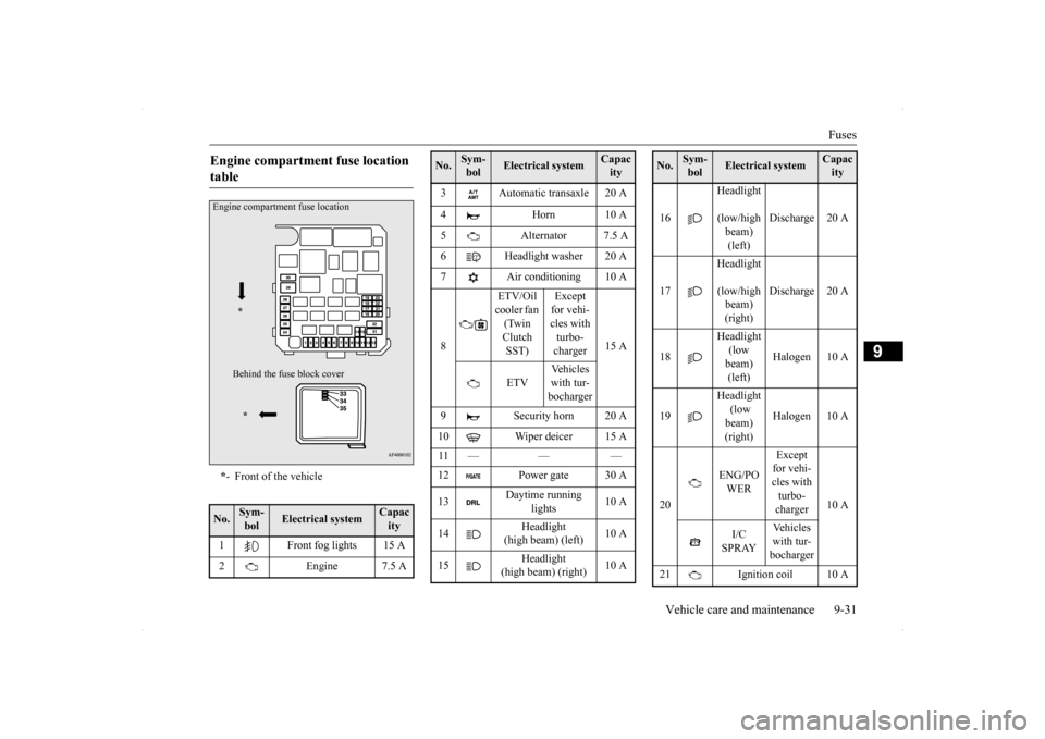
Engine compartment fuse location table * - Front of the vehicle
No.
Sym- bol
Electrical system
Capacity
1 Front fog lights 15 A 2 Engine 7.5 AEngine compartment fuse location
* Behind the fuse
block cover
*
3 Automatic transaxle 20 A 4 Horn 10 A 5 Alternator 7.5 A 6 Headlight washer 20 A 7 Air conditioning 10 A 8
/
ETV/Oil cooler fan (Twin Clutch SST)
Except for vehi- cles with turbo- charger
15 A
ETV
Vehicles with tur-bocharger
9 Security horn 20 A 10 Wiper deicer 15 A 11 — — — 12 Power gate 30 A 13
Daytime running
lights
10 A
14
Headlight
(high beam) (left)
10 A
15
Headlight
(high beam) (right)
10 A
No.
Sym- bol
Electrical system
Capacity
16
Headlight
(low/high beam) (left)
Discharge 20 A
17
Headlight
(low/high beam) (right)
Discharge 20 A
18
Headlight (low beam) (left)
Halogen 10 A
19
Headlight (low beam) (right)
Halogen 10 A
20
ENG/PO WER
Except for vehi- cles with turbo- charger
10 A
I/C SPRAY
Vehicles with tur-bocharger
21 Ignition coil 10 ANo.
Sym- bol
Electrical system
Capacity