rear MITSUBISHI LANCER EVOLUTION 2007 Service Owners Manual
[x] Cancel search | Manufacturer: MITSUBISHI, Model Year: 2007, Model line: LANCER EVOLUTION, Model: MITSUBISHI LANCER EVOLUTION 2007Pages: 1449, PDF Size: 56.82 MB
Page 501 of 1449
ENGINE OVERHAUL -Oil Pump and Oil Pan11B-47
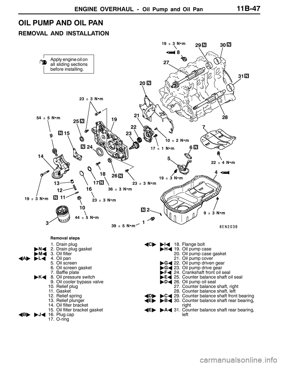
OIL PUMP AND OIL PAN
REMOVAL AND INSTALLATION
2
1
Apply engine oil on
all sliding sections
before installing.
4 56
12 13
16187 20
38
9
10 1415
1719
1139±5N•m 54±5N•m19±3N•m
36±3N•m23±3N•m 17±1N•m 10±2N•m
9±3N•m 22±4N•m 23±3N•m
19±3N•m
44±5N•m 23±3N•m
25
24232221
26272930
31
28
19±3N•m
Removal steps
1. Drain plug
"NA2. Drain plug gasket
"MA3. Oil filter
AA""LA4. Oil pan
5. Oil screen
6. Oil screen gasket
7. Baffle plate
"KA8. Oil pressure switch
9. Oil cooler bypass valve
10. Relief plug
11. Gasket
12. Relief spring
13. Relief plunger
14. Oil filter bracket
15. Oil filter bracket gasket
AB""JA16. Plug cap
17. O-ringAC""IA18. Flange bolt
"HA19. Oil pump case
20. Oil pump case gasket
21. Oil pump cover
"GA22. Oil pump driven gear
"GA23. Oil pump drive gear
"FA24. Crankshaft front oil seal
"EA25. Counter balance shaft oil seal
"DA26. Oil pump oil seal
27. Counter balance shaft, right
28. Counter balance shaft, left
AD""CA29. Counter balance shaft front bearing
AE""BA30. Counter balance shaft rear bearing,
right
AE""AA31. Counter balance shaft rear bearing,
left
Page 502 of 1449
ENGINE OVERHAUL -Oil Pump and Oil Pan11B-48
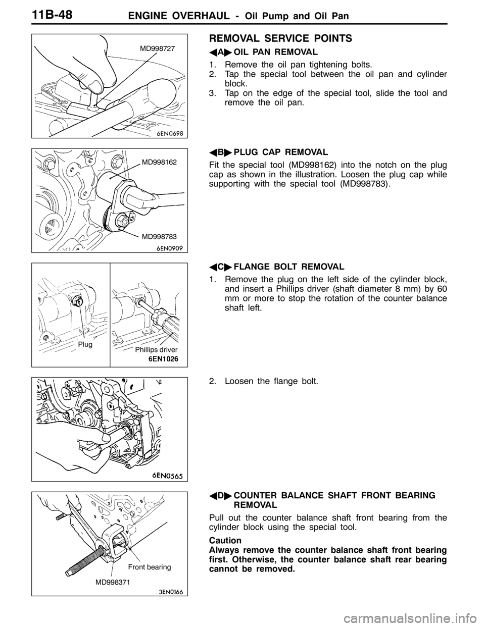
REMOVAL SERVICE POINTS
AA"OIL PAN REMOVAL
1. Remove the oil pan tightening bolts.
2. Tap the special tool between the oil pan and cylinder
block.
3. Tap on the edge of the special tool, slide the tool and
remove the oil pan.
AB"PLUG CAP REMOVAL
Fit the special tool (MD998162) into the notch on the plug
cap as shown in the illustration. Loosen the plug cap while
supporting with the special tool (MD998783).
AC"FLANGE BOLT REMOVAL
1. Remove the plug on the left side of the cylinder block,
and insert a Phillips driver (shaft diameter 8 mm) by 60
mm or more to stop the rotation of the counter balance
shaft left.
2. Loosen the flange bolt.
AD"COUNTER BALANCE SHAFT FRONT BEARING
REMOVAL
Pull out the counter balance shaft front bearing from the
cylinder block using the special tool.
Caution
Always remove the counter balance shaft front bearing
first. Otherwise, the counter balance shaft rear bearing
cannot be removed.MD998727
MD998162
MD998783
Plug
Phillips driver
MD998371Front bearing
Page 503 of 1449
ENGINE OVERHAUL -Oil Pump and Oil Pan11B-49
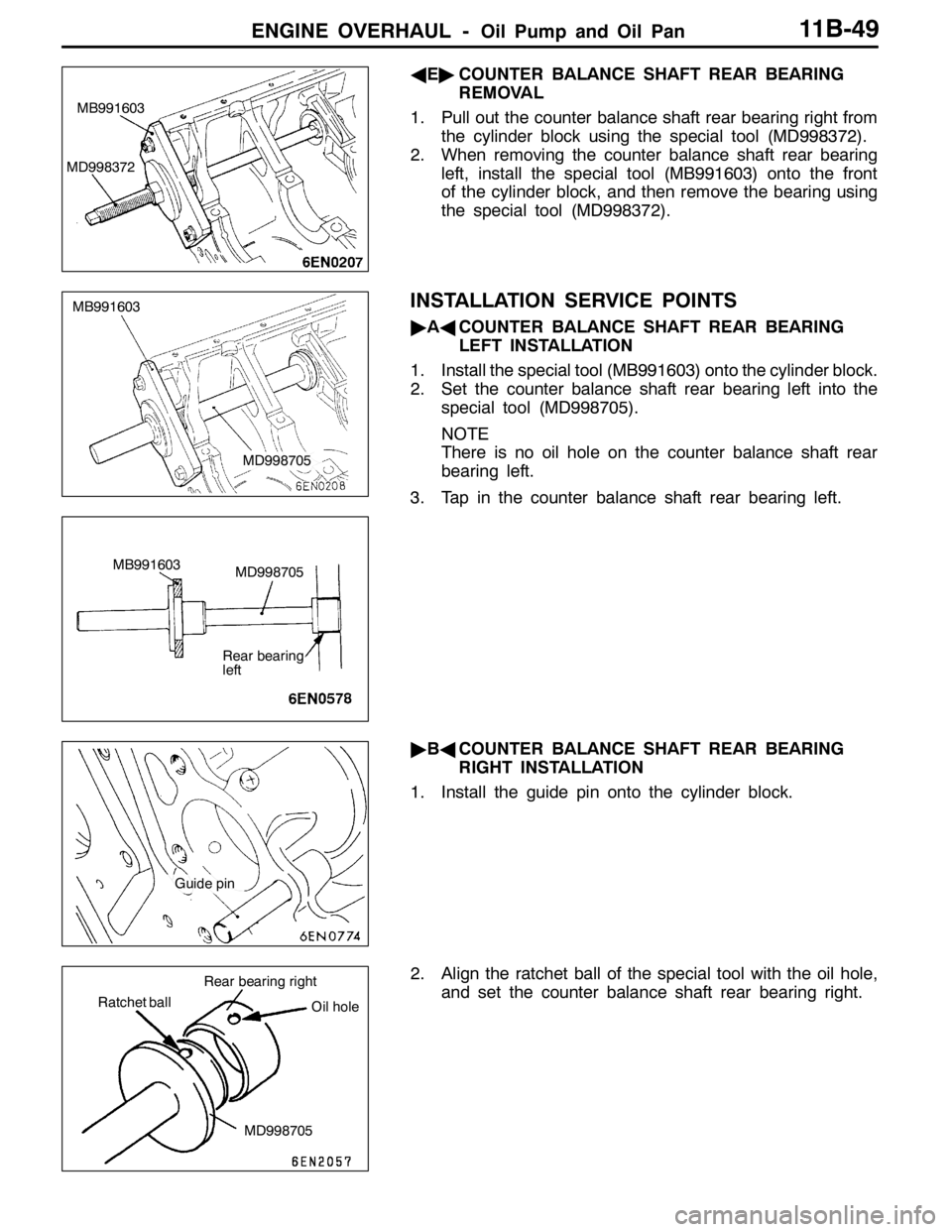
AE"COUNTER BALANCE SHAFT REAR BEARING
REMOVAL
1. Pull out the counter balance shaft rear bearing right from
the cylinder block using the special tool (MD998372).
2. When removing the counter balance shaft rear bearing
left, install the special tool (MB991603) onto the front
of the cylinder block, and then remove the bearing using
the special tool (MD998372).
INSTALLATION SERVICE POINTS
"AACOUNTER BALANCE SHAFT REAR BEARING
LEFT INSTALLATION
1. Install the special tool (MB991603) onto the cylinder block.
2. Set the counter balance shaft rear bearing left into the
special tool (MD998705).
NOTE
There is no oil hole on the counter balance shaft rear
bearing left.
3. Tap in the counter balance shaft rear bearing left.
"BACOUNTER BALANCE SHAFT REAR BEARING
RIGHT INSTALLATION
1. Install the guide pin onto the cylinder block.
2. Align the ratchet ball of the special tool with the oil hole,
and set the counter balance shaft rear bearing right.
MB991603
MD998372
MB991603
MD998705
MB991603
MD998705
Rear bearing
left
Guide pin
Ratchet ball
MD998705 Rear bearing right
Oil hole
Page 504 of 1449
ENGINE OVERHAUL -Oil Pump and Oil Pan11B-50
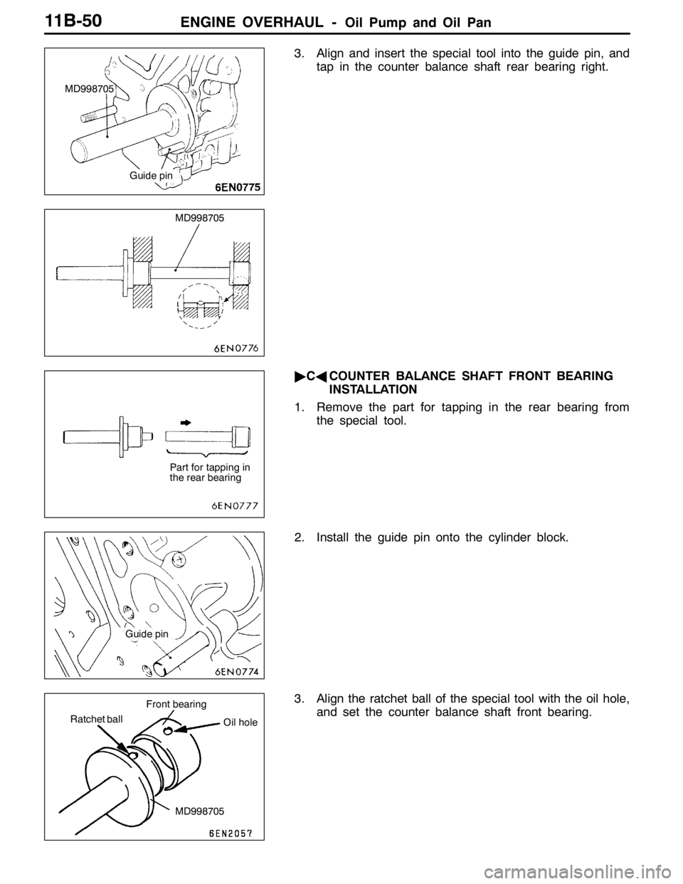
3. Align and insert the special tool into the guide pin, and
tap in the counter balance shaft rear bearing right.
"CACOUNTER BALANCE SHAFT FRONT BEARING
INSTALLATION
1. Remove the part for tapping in the rear bearing from
the special tool.
2. Install the guide pin onto the cylinder block.
3. Align the ratchet ball of the special tool with the oil hole,
and set the counter balance shaft front bearing.
MD998705
Guide pin
MD998705
Part for tapping in
the rear bearing
Guide pin
Ratchet ball
MD998705 Front bearing
Oil hole
Page 518 of 1449
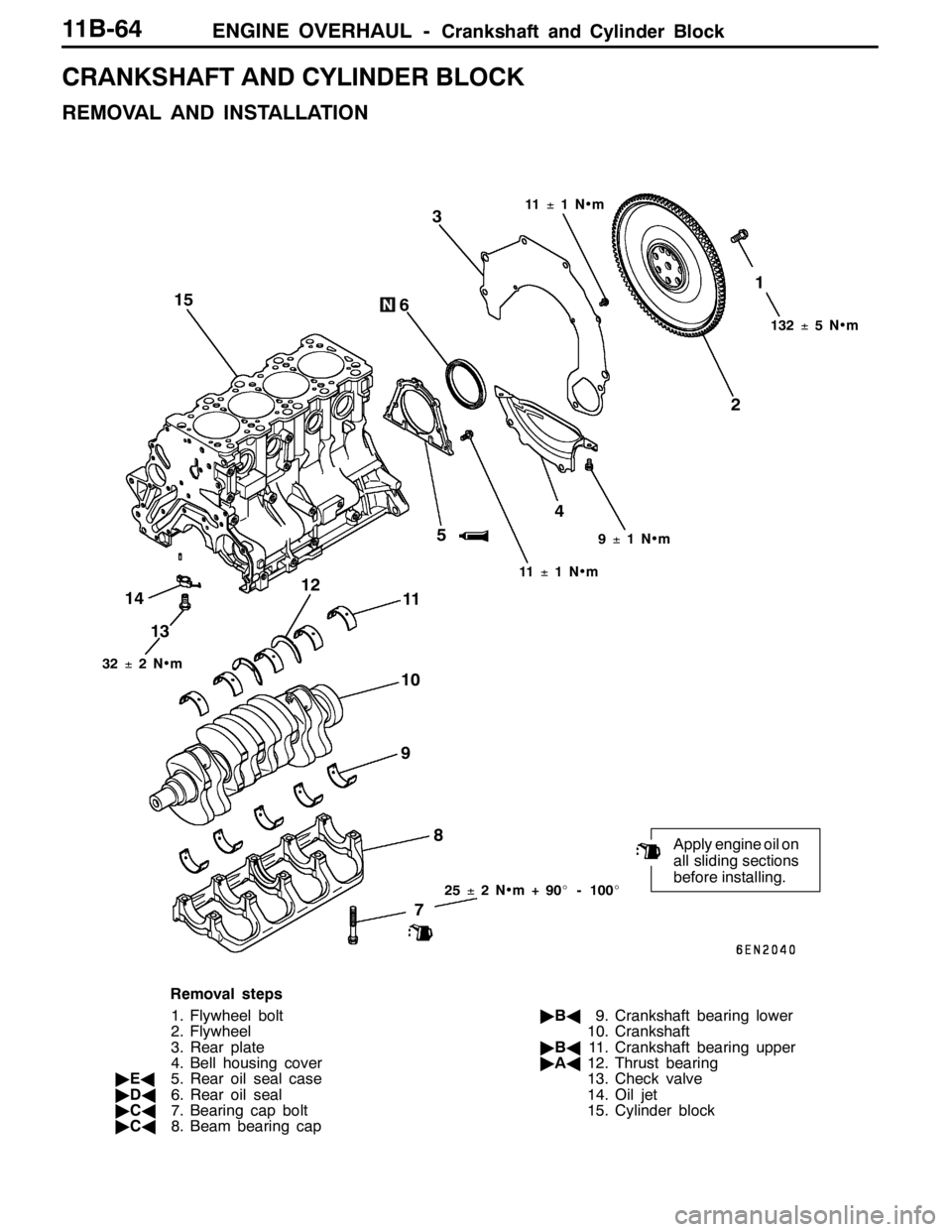
ENGINE OVERHAUL -Crankshaft and Cylinder Block11B-64
CRANKSHAFT AND CYLINDER BLOCK
REMOVAL AND INSTALLATION
25±2N•m+90_- 100_
21
Apply engine oil on
all sliding sections
before installing.
4
5 6
73
8 9 1011
132±5N•m 11±1N•m
11±1N•m9±1N•m
32±2N•m
14
1312 15
Removal steps
1. Flywheel bolt
2. Flywheel
3. Rear plate
4. Bell housing cover
"EA5. Rear oil seal case
"DA6. Rear oil seal
"CA7. Bearing cap bolt
"CA8. Beam bearing cap"BA9. Crankshaft bearing lower
10. Crankshaft
"BA11. Crankshaft bearing upper
"AA12. Thrust bearing
13. Check valve
14. Oil jet
15. Cylinder block
Page 521 of 1449
ENGINE OVERHAUL -Crankshaft and Cylinder Block11B-67
8. After installing the beam bearing cap, inspect the end
play of the crankshaft. If the end play exceeds the limit
value, replace the crankshaft bearing.
Standard value: 0.05 - 0.25 mm
Limit value: 0.4 mm
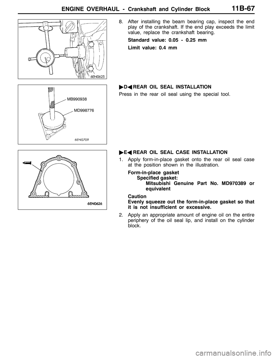
"DAREAR OIL SEAL INSTALLATION
Press in the rear oil seal using the special tool.
"EAREAR OIL SEAL CASE INSTALLATION
1. Apply form-in-place gasket onto the rear oil seal case
at the position shown in the illustration.
Form-in-place gasket
Specified gasket:
Mitsubishi Genuine Part No. MD970389 or
equivalent
Caution
Evenly squeeze out the form-in-place gasket so that
it is not insufficient or excessive.
2. Apply an appropriate amount of engine oil on the entire
periphery of the oil seal lip, and install on the cylinder
block.
MB990938
MD998776
Page 537 of 1449
MPI -General Information13A-5
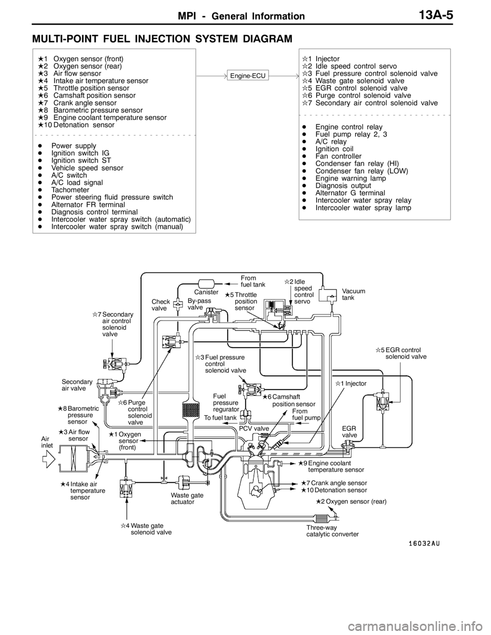
MULTI-POINT FUEL INJECTION SYSTEM DIAGRAM
L1 Oxygen sensor (front)
L2 Oxygen sensor (rear)
L3 Air flow sensor
L4 Intake air temperature sensor
L5 Throttle position sensor
L6 Camshaft position sensor
L7 Crank angle sensor
L8 Barometric pressure sensor
L9 Engine coolant temperature sensor
L10 Detonation sensor
Engine-ECU
l1 Injector
l2 Idle speed control servo
l3 Fuel pressure control solenoid valve
l4 Waste gate solenoid valve
l5 EGR control solenoid valve
l6 Purge control solenoid valve
l7 Secondary air control solenoid valve
DPower supply
DIgnition switch IG
DIgnition switch ST
DVehicle speed sensor
DA/C switch
DA/C load signal
DTachometer
DPower steering fluid pressure switch
DAlternator FR terminal
DDiagnosis control terminal
DIntercooler water spray switch (automatic)
DIntercooler water spray switch (manual)DEngine control relay
DFuel pump relay 2, 3
DA/C relay
DIgnition coil
DFan controller
DCondenser fan relay (HI)
DCondenser fan relay (LOW)
DEngine warning lamp
DDiagnosis output
DAlternator G terminal
DIntercooler water spray relay
DIntercooler water spray lamp
L1 Oxygen
sensor
(front)
L4 Intake air
temperature
sensorL5 Throttle
position
sensor
L6 Camshaft
position sensorl1 Injector l2 Idle
speed
control
servo
l6 Purge
control
solenoid
valve
Three-way
catalytic converter Canister
Air
inletVacuum
tank
Fuel
pressure
reguratorFrom
fuel tank
To fuel tank
PCV valveFrom
fuel pump
Waste gate
actuatorL2 Oxygen sensor (rear) Check
valveBy-pass
valve
l5 EGR control
solenoid valve
l4 Waste gate
solenoid valve L8 Barometric
pressure
sensor
L3 Air flow
sensorl7 Secondary
air control
solenoid
valve
Secondary
air valvel3 Fuel pressure
control
solenoid valve
EGR
valve
L9 Engine coolant
temperature sensor
L7 Crank angle sensor
L10 Detonation sensor
Page 538 of 1449
MPI -Service Specifications/Sealant13A-6
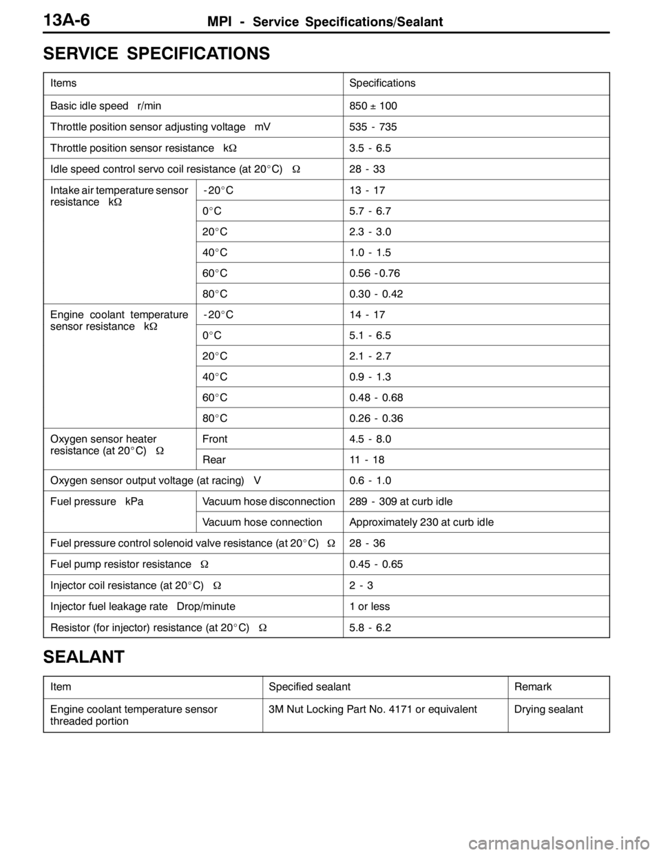
SERVICE SPECIFICATIONS
ItemsSpecifications
Basic idle speed r/min850±100
Throttle position sensor adjusting voltage mV535 - 735
Throttle position sensor resistance kΩ3.5 - 6.5
Idle speed control servo coil resistance (at 20_C)Ω28 - 33
Intake air temperature sensor
resistancekΩ
-20_C13 - 17
resistance kΩ0_C5.7 - 6.7
20_C2.3 - 3.0
40_C1.0 - 1.5
60_C0.56 - 0.76
80_C0.30 - 0.42
Engine coolant temperature
sensorresistancekΩ
-20_C14 - 17
sensor resistance kΩ0_C5.1 - 6.5
20_C2.1 - 2.7
40_C0.9 - 1.3
60_C0.48 - 0.68
80_C0.26 - 0.36
Oxygen sensor heater
resistance(at20_C)Ω
Front4.5 - 8.0
resistance (at 20_C)ΩRear11 - 1 8
Oxygen sensor output voltage (at racing) V0.6 - 1.0
Fuel pressure kPaVacuum hose disconnection289 - 309 at curb idle
Vacuum hose connectionApproximately 230 at curb idle
Fuel pressure control solenoid valve resistance (at 20_C)Ω28 - 36
Fuel pump resistor resistanceΩ0.45 - 0.65
Injector coil resistance (at 20_C)Ω2-3
Injector fuel leakage rate Drop/minute1 or less
Resistor (for injector) resistance (at 20_C)Ω5.8 - 6.2
SEALANT
ItemSpecified sealantRemark
Engine coolant temperature sensor
threaded portion3M Nut Locking Part No. 4171 or equivalentDrying sealant
Page 541 of 1449
MPI -Troubleshooting13A-9
TROUBLESHOOTING
DIAGNOSIS TROUBLESHOOTING FLOW
Refer to GROUP 00 - How to Use Troubleshooting/Inspection
Service Point.
NOTE
If the engine-ECU is replaced, the immobilizer-ECU and
ignition key should be replaced together with it.
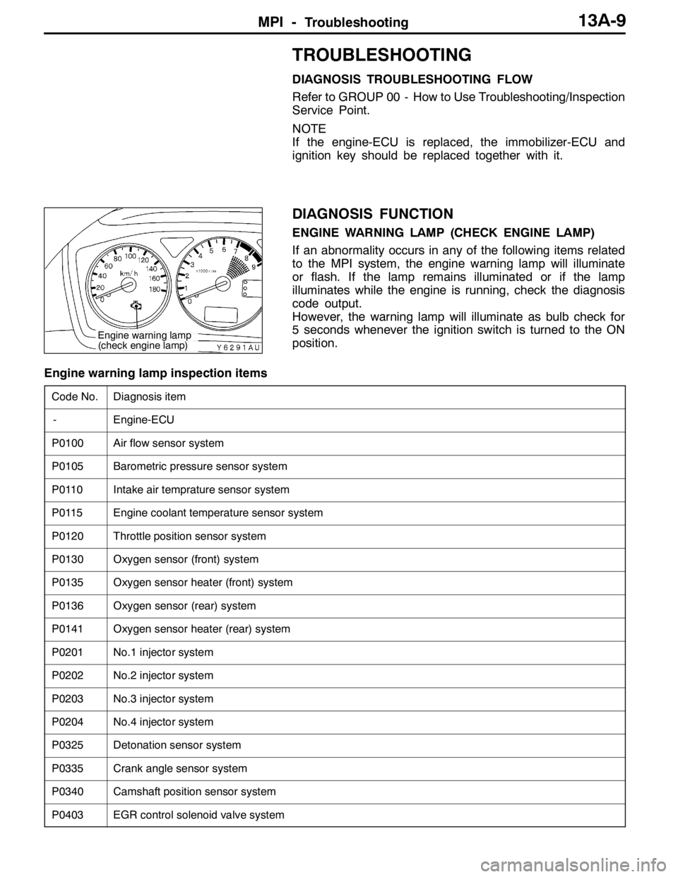
DIAGNOSIS FUNCTION
ENGINE WARNING LAMP (CHECK ENGINE LAMP)
If an abnormality occurs in any of the following items related
to the MPI system, the engine warning lamp will illuminate
or flash. If the lamp remains illuminated or if the lamp
illuminates while the engine is running, check the diagnosis
code output.
However, the warning lamp will illuminate as bulb check for
5 seconds whenever the ignition switch is turned to the ON
position.
Engine warning lamp inspection items
Code No.Diagnosis item
-Engine-ECU
P0100Air flow sensor system
P0105Barometric pressure sensor system
P0110Intake air temprature sensor system
P0115Engine coolant temperature sensor system
P0120Throttle position sensor system
P0130Oxygen sensor (front) system
P0135Oxygen sensor heater (front) system
P0136Oxygen sensor (rear) system
P0141Oxygen sensor heater (rear) system
P0201No.1 injector system
P0202No.2 injector system
P0203No.3 injector system
P0204No.4 injector system
P0325Detonation sensor system
P0335Crank angle sensor system
P0340Camshaft position sensor system
P0403EGR control solenoid valve system
Engine warning lamp
(check engine lamp)
Page 544 of 1449
MPI -Troubleshooting13A-12
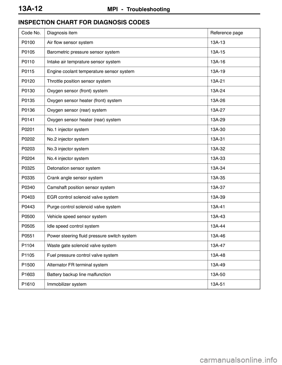
INSPECTION CHART FOR DIAGNOSIS CODES
Code No.Diagnosis itemReference page
P0100Air flow sensor system13A-13
P0105Barometric pressure sensor system13A-15
P0110Intake air temprature sensor system13A-16
P0115Engine coolant temperature sensor system13A-19
P0120Throttle position sensor system13A-21
P0130Oxygen sensor (front) system13A-24
P0135Oxygen sensor heater (front) system13A-26
P0136Oxygen sensor (rear) system13A-27
P0141Oxygen sensor heater (rear) system13A-29
P0201No.1 injector system13A-30
P0202No.2 injector system13A-31
P0203No.3 injector system13A-32
P0204No.4 injector system13A-33
P0325Detonation sensor system13A-34
P0335Crank angle sensor system13A-35
P0340Camshaft position sensor system13A-37
P0403EGR control solenoid valve system13A-39
P0443Purge control solenoid valve system13A-41
P0500Vehicle speed sensor system13A-43
P0505Idle speed control system13A-44
P0551Power steering fluid pressure switch system13A-46
P1104Waste gate solenoid valve system13A-47
P1105Fuel pressure control valve system13A-48
P1500Alternator FR terminal system13A-49
P1603Battery backup line malfunction13A-50
P1610Immobilizer system13A-51