rear MITSUBISHI LANCER EVOLUTION 2007 Service Repair Manual
[x] Cancel search | Manufacturer: MITSUBISHI, Model Year: 2007, Model line: LANCER EVOLUTION, Model: MITSUBISHI LANCER EVOLUTION 2007Pages: 1449, PDF Size: 56.82 MB
Page 559 of 1449

MPI -Troubleshooting13A-27
Code No. P0136 Oxygen sensor (rear) systemProbable cause
Inspection Range
DMore than 3 minutes passed after completion of start of engine
DThe engine coolant temperature is approximately more than 80_C.
DThe engine speed is more than 1,200 r/min.
DThe volumetric efficiency is 25% or more.
Evaluation Conditions
DWhen 5 V is applied to the oxygen sensor (rear), the output voltage is more
than 4.5 V.DOxygen sensor (rear) malfunction
DOxygen sensor (rear) circuit disconnection,
short-circuit, or connector contact defect.
DEngine-ECU malfunction
OK
To the next pageOK
Check the harness between the
oxygen sensor (rear) and engine-ECU.
DCheck for damage of the output
wire.NG
Repair NG
OK
Check the following connector:
C-115Repair
(2) NGCheck the oxygen sensor (rear).
(Refer to P.13A-135.)NGReplace the oxygen sensor (rear).
OK
Check the harness between the
oxygen sensor (rear) and engine-ECU.
DCheck for damage of the earth
wire.NG
Repair
OK
Measure at the D-22 oxygen sensor
(rear) connector.
DUsing the test harness
(MB998464), connect the
connector, and measure at the
pickup harness.
DEngine: After warm-up
(1) Voltage between terminal No. 2
and earth
OK:Less than 0.5 V
(2) Voltage between terminal No. 1
and the earth
DDuring rapid racing
OK:0 and 600 - 1,000 mV
alternate.(1) NGCheck the following connector:
C-115NG
Repair
OK
Intermittent malfunction
(Refer to GROUP 00 - Points to Note
for Intermittent Malfunctions.)
OK
MUT-IIData list
DNo. 59 Oxygen sensor (rear)
(Refer to P.13A-105.)NGReplace engine-ECU.
OK
Check the harness between the
oxygen sensor (rear) and engine-ECU.
DCheck for disconnection and
damage of the earth wire.NG
Repair
OK
Measure at the D-22 oxygen sensor
(rear) connector.
DDisconnect connector to measure
at the harness side
DResistance between terminal No.
2 and earth.
OK:Less than 2ΩNGCheck the following connector:
C-115NG
Repair
NG
Check the following connector:
D-22NG
Repair
MUT-IIData list
DNo. 59 Oxygen sensor (rear)
(Refer to P.13A-105.)OKIntermittent malfunction
(Refer to GROUP 00 - Points to Note
for Intermittent Malfunctions.)
Page 560 of 1449

MPI -Troubleshooting13A-28
OK
Intermittent malfunction
(Refer to GROUP 00 - Points to Note
for Intermittent Malfunctions.)
OK
MUT-IIData list
DNo. 59 Oxygen sensor (rear)
(Refer to P.13A-105.)NGReplace the engine-ECU.
OK
Check the following connector:
C-115NG
Repair
OK
Check and repair the harness between
the oxygen sensor (rear) and
engine-ECU.
DCheck for disconnection of the
output wire.
OK
Test at the C-115 engine-ECU
connector.
DMeasure the engine-ECU terminal
voltage.
DEngine: After warm-up
DVoltage between terminal No. 75
and earth.
DDuring rapid racing
OK:0 and 600 - 1,000 mV
alternate.NGCheck the following connector:
C-115NG
Repair
From the previous page
Page 561 of 1449
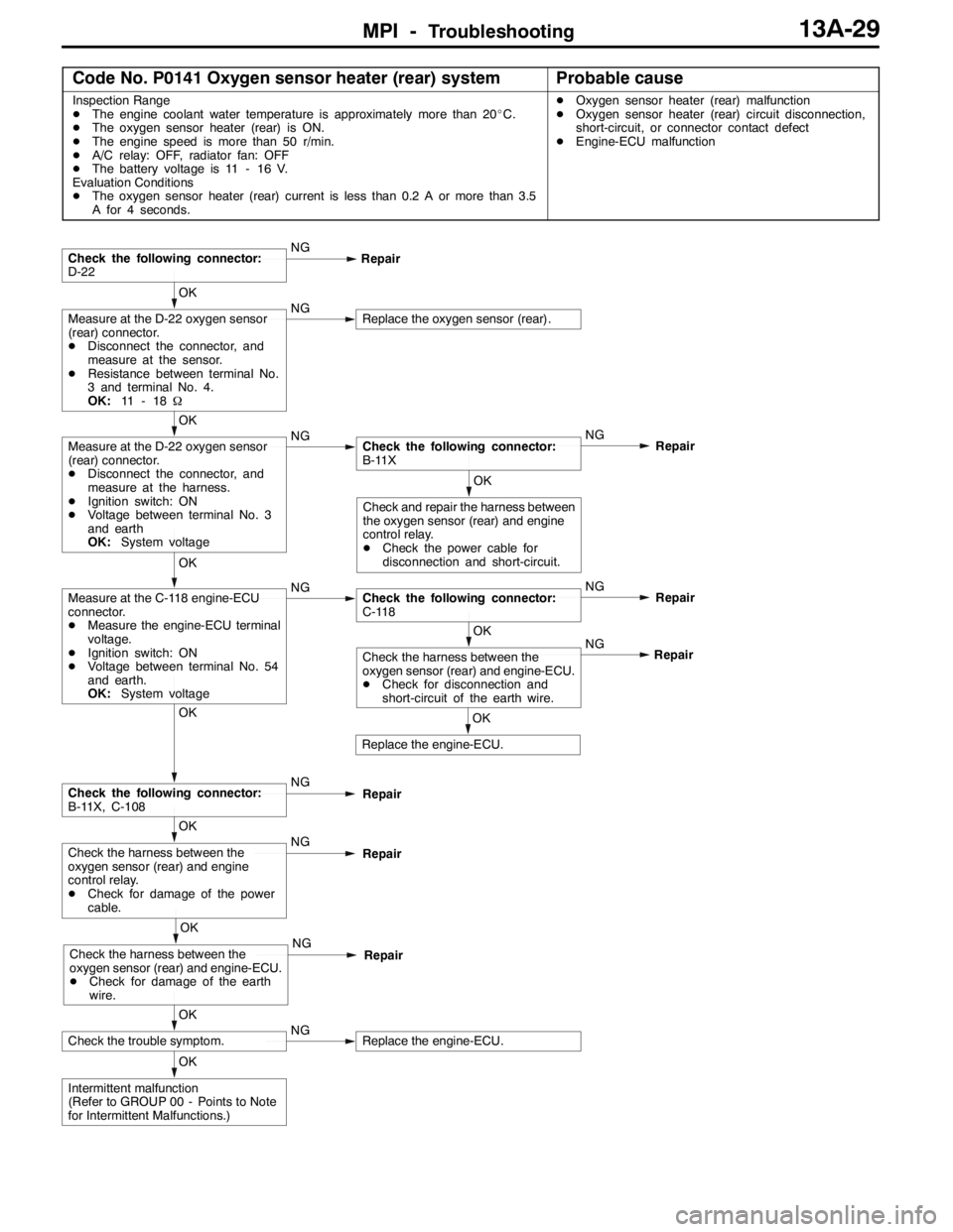
MPI -Troubleshooting13A-29
Code No. P0141 Oxygen sensor heater (rear) systemProbable cause
Inspection Range
DThe engine coolant water temperature is approximately more than 20_C.
DThe oxygen sensor heater (rear) is ON.
DThe engine speed is more than 50 r/min.
DA/C relay: OFF, radiator fan: OFF
DThe battery voltage is 11 - 16 V.
Evaluation Conditions
DThe oxygen sensor heater (rear) current is less than 0.2 A or more than 3.5
A for 4 seconds.DOxygen sensor heater (rear) malfunction
DOxygen sensor heater (rear) circuit disconnection,
short-circuit, or connector contact defect
DEngine-ECU malfunction
OK
Intermittent malfunction
(Refer to GROUP 00 - Points to Note
for Intermittent Malfunctions.)
OK
Check the trouble symptom.NGReplace the engine-ECU.
OK
Check the harness between the
oxygen sensor (rear) and engine-ECU.
DCheck for damage of the earth
wire.NG
Repair
OK
Check the harness between the
oxygen sensor (rear) and engine
control relay.
DCheck for damage of the power
cable.NG
Repair
OK
Check the following connector:
B-11X, C-108NG
Repair
OK
Replace the engine-ECU.NG
OK
Check the harness between the
oxygen sensor (rear) and engine-ECU.
DCheck for disconnection and
short-circuit of the earth wire.Repair
OK
Measure at the C-118 engine-ECU
connector.
DMeasure the engine-ECU terminal
voltage.
DIgnition switch: ON
DVoltage between terminal No. 54
and earth.
OK:System voltageNGCheck the following connector:
C-118NG
Repair
OK
Check and repair the harness between
the oxygen sensor (rear) and engine
control relay.
DCheck the power cable for
disconnection and short-circuit.
OK
Measure at the D-22 oxygen sensor
(rear) connector.
DDisconnect the connector, and
measure at the harness.
DIgnition switch: ON
DVoltage between terminal No. 3
and earth
OK:System voltageNGCheck the following connector:
B-11XNG
Repair
OK
Measure at the D-22 oxygen sensor
(rear) connector.
DDisconnect the connector, and
measure at the sensor.
DResistance between terminal No.
3 and terminal No. 4.
OK:11 - 1 8ΩNGReplace the oxygen sensor (rear).
Check the following connector:
D-22NG
Repair
Page 596 of 1449
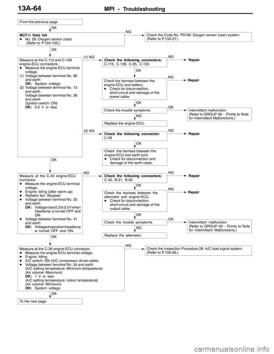
MPI -Troubleshooting13A-64
OK
To the next page
OK
Measure at the C-39 engine-ECU connector.
DMeasure the engine-ECU terminal voltage.
DEngine: Idling
DA/C switch: ON (A/C compressor driven state)
DVoltage between terminal No .24 and earth
(A/C setting temperature: Minimum temperature)
(Air volume: Maximum)
OK:1 V or less
(A/C setting temperature: indoor temperature)
(Air volume: Minimum)
OK:System voltageNGCheck the Inspection Procedure 28: A/C load signal system.
(Refer to P.13A-95.)
NG
Replace the alternator.
OK
Check the trouble symptoms.OKIntermittent malfunction
(Refer to GROUP 00 - Points to Note
for Intermittent Malfunctions.) NG
OK
Check the harness between the
alternator and engine-ECU.
DCheck for disconnection,
short-circuit and damage of the
output cable.Repair
OK
Measure at the C-40 engine-ECU
connector.
DMeasure the engine-ECU terminal
voltage.
DEngine: Idling (after warm-up)
DRadiator fan: Stopped
DVoltage between terminal No. 33
and earth
OK:Voltage rises 0.2 to 3.5 V when
headlamp is turned OFF and
ON.
DVoltage between terminal No. 41
and earth
OK:Voltage drops whenheadlamp
is turned OFF and ON.NGCheck the following connectors:
C-40, B-21, B-03NG
Repair
OK
Check the harness between the
engine-ECU and earth joint.
DCheck for disconnection and
damage of the earth cable.
(2) NGCheck the following connector:
C-39NG
Repair
NG
Replace the engine-ECU.
OK
Check the trouble symptoms.OKIntermittent malfunction
(Refer to GROUP 00 - Points to Note
for Intermittent Malfunctions.) NG
OK
Check the harness between the
engine-ECU and battery.
DCheck for disconnection,
short-circuit and damage of the
power cable.Repair
OK
Measure at the C-115 and C-126
engine-ECU connectors.
DMeasure the engine-ECU terminal
voltage.
(1) Voltage between terminal No. 80
and earth
OK:System voltage
(2) Voltage between terminal No. 13
and earth
Voltage between terminal No. 26
and earth
(Ignition switch: ON)
OK:0.5 V or less(1) NGCheck the following connectors:
C-115, C-129, C-05, C-135NG
Repair
OK
MUT-IIData list
DNo. 59: Oxygen sensor (rear)
(Refer to P.13A-105.)NGCheck the Code No. P0136: Oxygen sensor (rear) system.
(Refer to P.13A-27.)
From the previous page
Page 600 of 1449
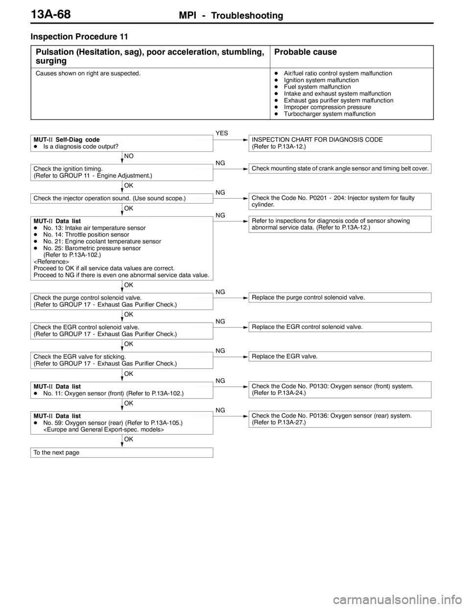
MPI -Troubleshooting13A-68
Inspection Procedure 11
Pulsation (Hesitation, sag), poor acceleration, stumbling,
surging
Probable cause
Causes shown on right are suspected.DAir/fuel ratio control system malfunction
DIgnition system malfunction
DFuel system malfunction
DIntake and exhaust system malfunction
DExhaust gas purifier system malfunction
DImproper compression pressure
DTurbocharger system malfunction
OK
To the next page
OK
MUT-IIData list
DNo. 59: Oxygen sensor (rear) (Refer to P.13A-105.)
(Refer to P.13A-27.)
OK
MUT-IIData list
DNo. 11: Oxygen sensor (front) (Refer to P.13A-102.)NGCheck the Code No. P0130: Oxygen sensor (front) system.
(Refer to P.13A-24.)
OK
Check the EGR valve for sticking.
(Refer to GROUP 17 - Exhaust Gas Purifier Check.)NGReplace the EGR valve.
OK
Check the EGR control solenoid valve.
(Refer to GROUP 17 - Exhaust Gas Purifier Check.)NGReplace the EGR control solenoid valve.
OK
Check the purge control solenoid valve.
(Refer to GROUP 17 - Exhaust Gas Purifier Check.)NGReplace the purge control solenoid valve.
OK
MUT-IIData list
DNo. 13: Intake air temperature sensor
DNo. 14: Throttle position sensor
DNo. 21: Engine coolant temperature sensor
DNo. 25: Barometric pressure sensor
(Refer to P.13A-102.)
Proceed to OK if all service data values are correct.
Proceed to NG if there is even one abnormal service data value.NGRefer to inspections for diagnosis code of sensor showing
abnormal service data. (Refer to P.13A-12.)
OK
Check the injector operation sound. (Use sound scope.)NGCheck the Code No. P0201 - 204: Injector system for faulty
cylinder.
NO
Check the ignition timing.
(Refer to GROUP 11 - Engine Adjustment.)NGCheck mounting state of crank angle sensor and timing belt cover.
MUT-IISelf-Diag code
DIs a diagnosis code output?YESINSPECTION CHART FOR DIAGNOSIS CODE
(Refer to P.13A-12.)
Page 607 of 1449
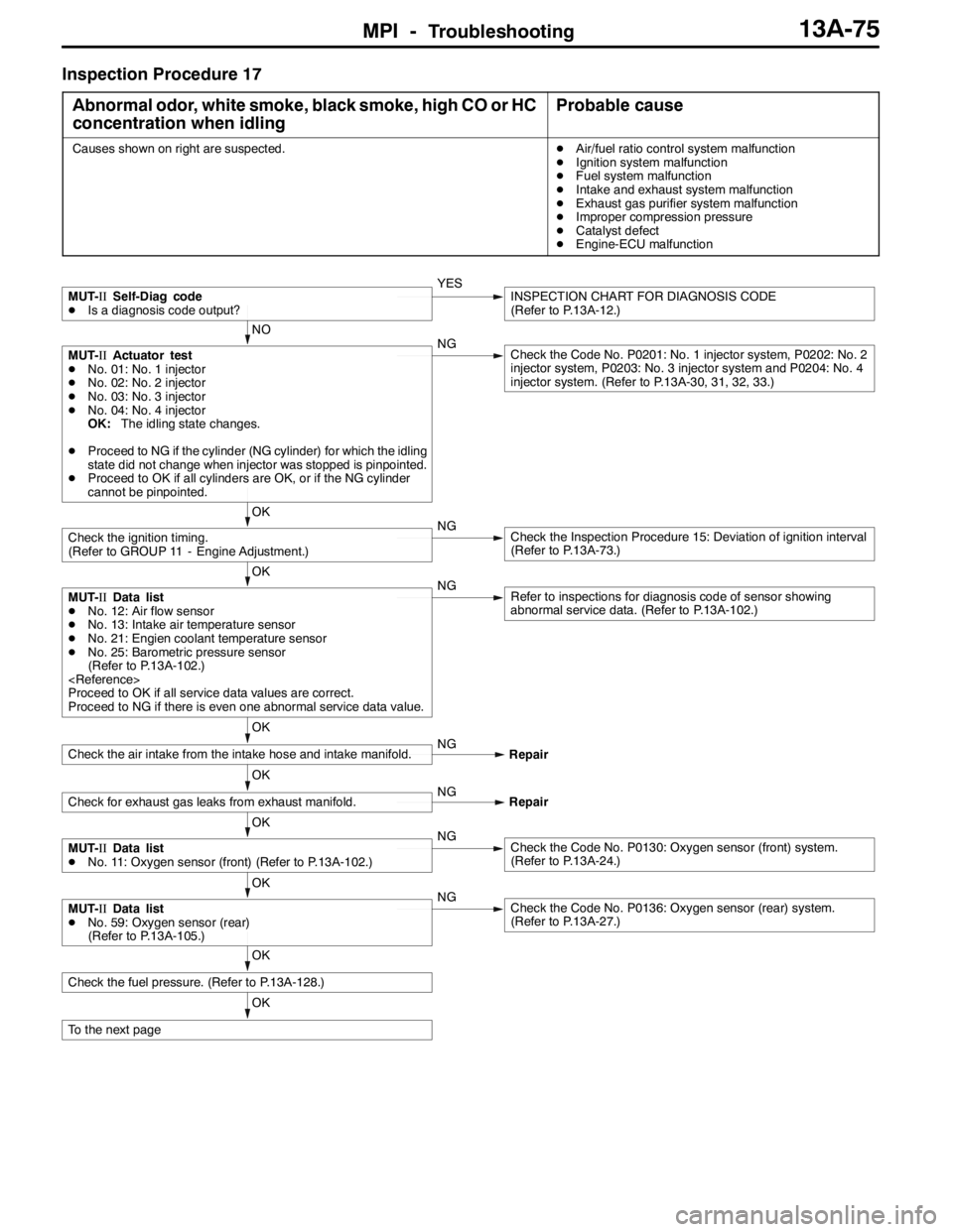
MPI -Troubleshooting13A-75
Inspection Procedure 17
Abnormal odor, white smoke, black smoke, high CO or HC
concentration when idling
Probable cause
Causes shown on right are suspected.DAir/fuel ratio control system malfunction
DIgnition system malfunction
DFuel system malfunction
DIntake and exhaust system malfunction
DExhaust gas purifier system malfunction
DImproper compression pressure
DCatalyst defect
DEngine-ECU malfunction
OK
To the next page
OK
Check the fuel pressure. (Refer to P.13A-128.)
OK
MUT-IIData list
DNo. 59: Oxygen sensor (rear)
(Refer to P.13A-105.)NGCheck the Code No. P0136: Oxygen sensor (rear) system.
(Refer to P.13A-27.)
OK
MUT-IIData list
DNo. 11: Oxygen sensor (front) (Refer to P.13A-102.)NGCheck the Code No. P0130: Oxygen sensor (front) system.
(Refer to P.13A-24.)
OK
Check for exhaust gas leaks from exhaust manifold.NG
Repair
OK
Check the air intake from the intake hose and intake manifold.NG
Repair
OK
MUT-IIData list
DNo. 12: Air flow sensor
DNo. 13: Intake air temperature sensor
DNo. 21: Engien coolant temperature sensor
DNo. 25: Barometric pressure sensor
(Refer to P.13A-102.)
Proceed to OK if all service data values are correct.
Proceed to NG if there is even one abnormal service data value.NGRefer to inspections for diagnosis code of sensor showing
abnormal service data. (Refer to P.13A-102.)
OK
Check the ignition timing.
(Refer to GROUP 11 - Engine Adjustment.)NGCheck the Inspection Procedure 15: Deviation of ignition interval
(Refer to P.13A-73.)
NO
MUT-IIActuator test
DNo. 01: No. 1 injector
DNo. 02: No. 2 injector
DNo. 03: No. 3 injector
DNo. 04: No. 4 injector
OK:The idling state changes.
DProceed to NG if the cylinder (NG cylinder) for which the idling
state did not change when injector was stopped is pinpointed.
DProceed to OK if all cylinders are OK, or if the NG cylinder
cannot be pinpointed.NGCheck the Code No. P0201: No. 1 injector system, P0202: No. 2
injector system, P0203: No. 3 injector system and P0204: No. 4
injector system. (Refer to P.13A-30, 31, 32, 33.)
MUT-IISelf-Diag code
DIs a diagnosis code output?YESINSPECTION CHART FOR DIAGNOSIS CODE
(Refer to P.13A-12.)
Page 637 of 1449
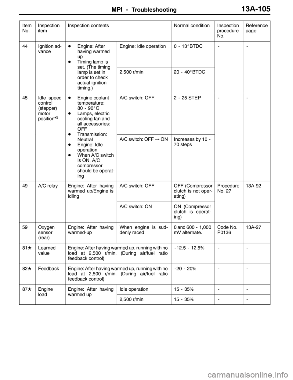
MPI -Troubleshooting13A-105
Item
No.Reference
page Inspection
procedure
No. Normal condition Inspection contents Inspection
item
44Ignition ad-
vanceDEngine: After
having warmed
up
DTiming lamp is
set(Thetiming
Engine: Idle operation0-13_BTDC--
set.(Thetiming
lamp is set in
order to check
actual ignition
timing.)
2,500 r/min20 - 40_BTDC
45Idle speed
control
(stepper)
motor
position*
3
DEngine coolant
temperature:
80 - 90_C
DLamps, electric
cooling fan and
all accessories:
OFF
DTransmission:
A/C switch: OFF2 - 25 STEP--
DTransmission:
Neutral
DEngine: Idle
operation
DWhen A/C switch
is ON, A/C
compressor
should be operat-
ing
A/C switch: OFF→ONIncreases by 10 -
70 steps
49A/C relayEngine: After having
warmed up/Engine is
idlingA/C switch: OFFOFF (Compressor
clutch is not oper-
ating)Procedure
No. 2713A-92
A/C switch: ONON (Compressor
clutch is operat-
ing)
59Oxygen
sensor
(rear)Engine: After having
warmed-upWhen engine is sud-
denly raced0 and 600 - 1,000
mV alternate.Code No.
P013613A-27
81LLearned
valueEngine: After having warmed up, running with no
load at 2,500 r/min. (During air/fuel ratio
feedback control)- 12.5 - 12.5%--
82LFeedbackEngine: After having warmed up, running with no
load at 2,500 r/min. (During air/fuel ratio
feedback control)- 20 - 20%--
87LEngine
load
Engine: After having
warmedup
Idle operation15 - 35%--
loadwarmedup
2,500 r/min15 - 35%--
Page 638 of 1449
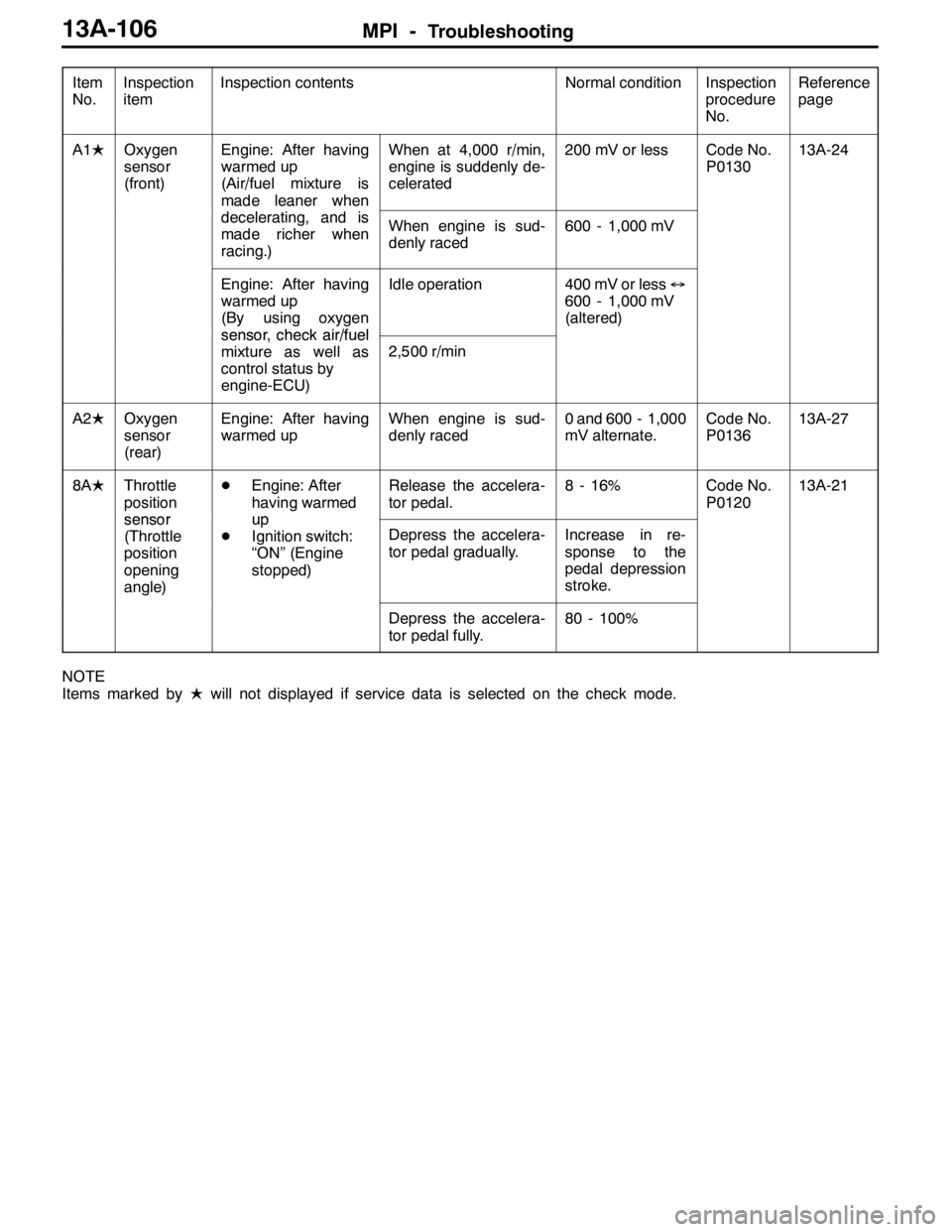
MPI -Troubleshooting13A-106
Item
No.Reference
page Inspection
procedure
No. Normal condition Inspection contents Inspection
item
A1LOxygen
sensor
(front)Engine: After having
warmed up
(Air/fuel mixture is
made leaner whenWhen at 4,000 r/min,
engine is suddenly de-
celerated200 mV or lessCode No.
P013013A-24
madeleanerwhen
decelerating, and is
made richer when
racing.)When engine is sud-
denly raced600 - 1,000 mV
Engine: After having
warmed up
(By using oxygen
sensorcheckair/fuel
Idle operation400 mV or less↔
600 - 1,000 mV
(altered)
sensor, checkair/fuel
mixture as well as
control status by
engine-ECU)2,500 r/min
A2LOxygen
sensor
(rear)Engine: After having
warmed upWhen engine is sud-
denly raced0 and 600 - 1,000
mV alternate.Code No.
P013613A-27
8ALThrottle
position
sensor
DEngine: After
having warmed
up
Release the accelera-
tor pedal.8 - 16%Code No.
P012013A-21
sensor
(Throttle
position
opening
angle)up
DIgnition switch:
“ON” (Engine
stopped)Depress the accelera-
tor pedal gradually.Increase in re-
sponse to the
pedal depression
stroke.
Depress the accelera-
tor pedal fully.80 - 100%
NOTE
Items marked byLwill not displayed if service data is selected on the check mode.
Page 642 of 1449
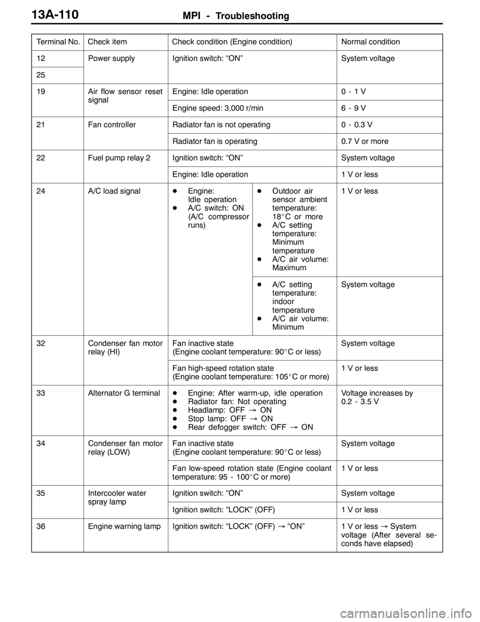
MPI -Troubleshooting13A-110
Terminal No.Normal condition Check condition (Engine condition) Check item
12Power supplyIgnition switch: “ON”System voltage
25
19Air flow sensor reset
signal
Engine: Idle operation0-1V
signal
Engine speed: 3,000 r/min6-9V
21Fan controllerRadiator fan is not operating0 - 0.3 V
Radiator fan is operating0.7 V or more
22Fuel pump relay 2Ignition switch: “ON”System voltage
Engine: Idle operation1 V or less
24A/C load signalDEngine:
Idle operation
DA/C switch: ON
(A/C compressor
runs)DOutdoor air
sensor ambient
temperature:
18_C or more
DA/C setting
temperature:
Minimum
temperature
DA/C air volume:
Maximum1 V or less
DA/C setting
temperature:
indoor
temperature
DA/C air volume:
MinimumSystem voltage
32Condenser fan motor
relay (HI)Fan inactive state
(Engine coolant temperature: 90_C or less)System voltage
Fan high-speed rotation state
(Engine coolant temperature: 105_C or more)1 V or less
33Alternator G terminalDEngine: After warm-up, idle operation
DRadiator fan: Not operating
DHeadlamp: OFF→ON
DStop lamp: OFF→ON
DRear defogger switch: OFF→ONVoltage increases by
0.2 - 3.5 V
34Condenser fan motor
relay (LOW)Fan inactive state
(Engine coolant temperature: 90_C or less)System voltage
Fan low-speed rotation state (Engine coolant
temperature: 95 - 100_C or more)1 V or less
35Intercooler water
spraylamp
Ignition switch: “ON”System voltage
spraylamp
Ignition switch: “LOCK” (OFF)1 V or less
36Engine warning lampIgnition switch: “LOCK” (OFF)→“ON”1 V or less→System
voltage (After several se-
conds have elapsed)
Page 643 of 1449
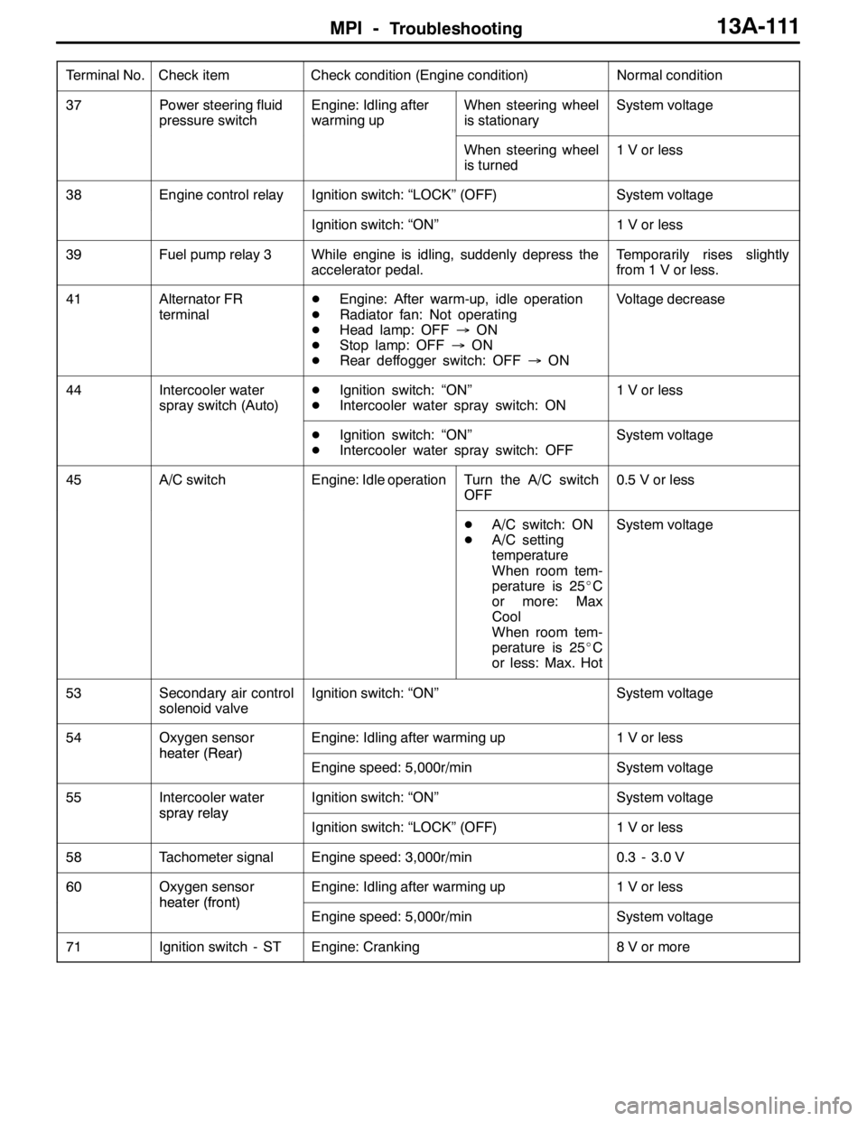
MPI -Troubleshooting13A-111
Terminal No.Normal condition Check condition (Engine condition) Check item
37Power steering fluid
pressure switchEngine: Idling after
warming upWhen steering wheel
is stationarySystem voltage
When steering wheel
is turned1 V or less
38Engine control relayIgnition switch: “LOCK” (OFF)System voltage
Ignition switch: “ON”1 V or less
39Fuel pump relay 3While engine is idling, suddenly depress the
accelerator pedal.Temporarily rises slightly
from 1 V or less.
41Alternator FR
terminalDEngine: After warm-up, idle operation
DRadiator fan: Not operating
DHead lamp: OFF→ON
DStop lamp: OFF→ON
DRear deffogger switch: OFF→ONVoltage decrease
44Intercooler water
spray switch (Auto)DIgnition switch: “ON”
DIntercooler water spray switch: ON1 V or less
DIgnition switch: “ON”
DIntercooler water spray switch: OFFSystem voltage
45A/C switchEngine: Idle operationTurn the A/C switch
OFF0.5 V or less
DA/C switch: ON
DA/C setting
temperature
When room tem-
perature is 25_C
or more: Max
Cool
When room tem-
perature is 25_C
or less: Max. HotSystem voltage
53Secondary air control
solenoid valveIgnition switch: “ON”System voltage
54Oxygen sensor
heater(Rear)
Engine: Idling after warming up1 V or less
heater(Rear)
Engine speed: 5,000r/minSystem voltage
55Intercooler water
sprayrelay
Ignition switch: “ON”System voltage
spray relay
Ignition switch: “LOCK” (OFF)1 V or less
58Tachometer signalEngine speed: 3,000r/min0.3 - 3.0 V
60Oxygen sensor
heater(front)
Engine: Idling after warming up1 V or less
heater(front)
Engine speed: 5,000r/minSystem voltage
71Ignition switch - STEngine: Cranking8 V or more