engine MITSUBISHI LANCER EVOLUTION 2007 Service User Guide
[x] Cancel search | Manufacturer: MITSUBISHI, Model Year: 2007, Model line: LANCER EVOLUTION, Model: MITSUBISHI LANCER EVOLUTION 2007Pages: 1449, PDF Size: 56.82 MB
Page 99 of 1449

B-1
ELECTRICAL
WIRING
CONTENTS
WIRING HARNESS CONFIGURATION
DIAGRAMS 4.........................
OVERALL WIRING DIAGRAM
L.H. drive vehicles 4........................
R.H. drive vehicles 5........................
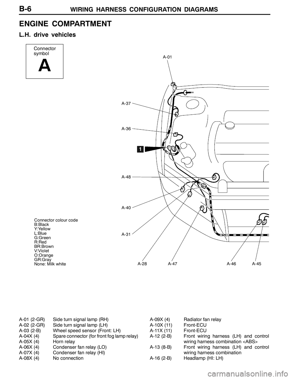
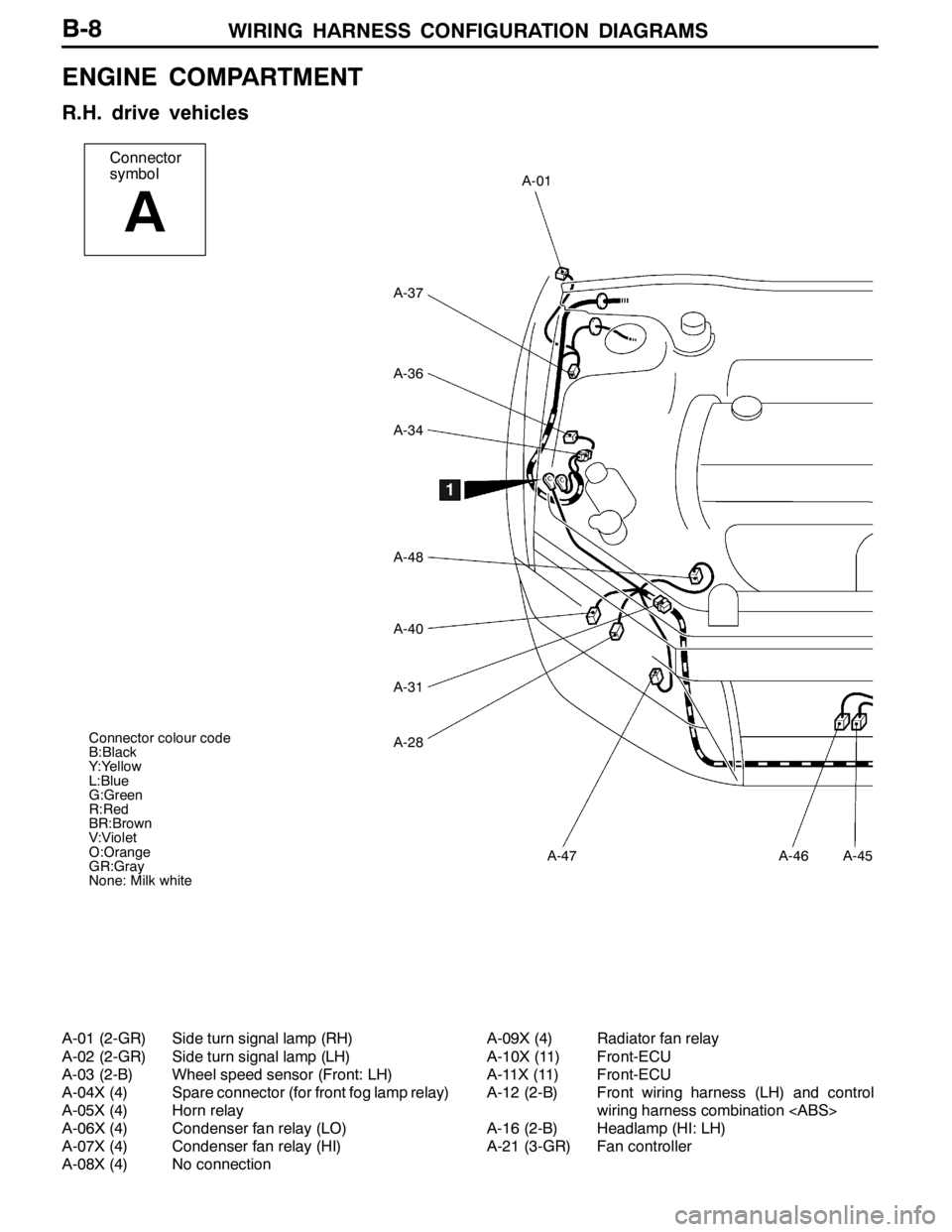
ENGINE COMPARTMENT
L.H. drive vehicles 6........................
R.H. drive vehicles 8........................
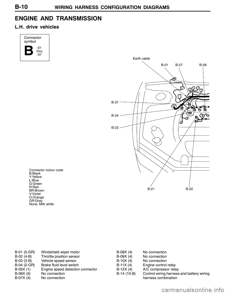
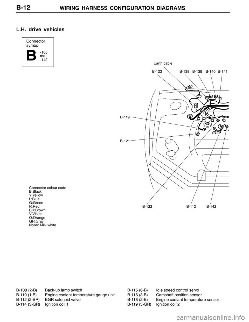
ENGINE AND TRANSMISSION
L.H. drive vehicles 10.......................
R.H. drive vehicles 14.......................
DASH PANEL
L.H. drive vehicles 18.......................
R.H. drive vehicles 24.......................
FLOOR AND ROOF
L.H. drive vehicles 30.......................
R.H. drive vehicles 32.......................
DOOR
L.H. drive vehicles 34.......................
R.H. drive vehicles 36.......................
LUGGAGE COMPARTMENT
L.H. drive vehicles 38.......................
R.H. drive vehicles 39.......................
SINGLE PART INSTALLATION
POSITION 40.........................
RELAY 40.................................
ECU 41...................................
SENSOR 43...............................
SOLENOID VALVE 46......................
INSPECTION CONNECTOR AND SPARE
CONNECTOR 47...........................
FUSIBLE LINK AND FUSE 48..............
EARTH CABLE 49.........................
EARTH 50.................................
CIRCUIT DIAGRAMS 54...............
J/B 54....................................
J/C
L.H. drive vehicles 56.......................
R.H. drive vehicles 62.......................
CENTRALIZED JUNCTION 68..............
POWER DISTRIBUTION SYSTEM 74........
STARTING SYSTEM 79....................
Page 100 of 1449

B-2
S
PWGEE
IGNITION SYSTEM
L.H. drive vehicles 82.......................
R.H. drive vehicles 83.......................
CHARGING SYSTEM 84...................
ENGINE CONTROL SYSTEM
L.H. drive vehicles 86.......................
R.H. drive vehicles 94.......................
COOLING SYSTEM 102...................
HEADLAMP
L.H. drive vehicles 103......................
R.H. drive vehicles 106......................
TAIL LAMP, POSITION LAMP, LICENCE
PLATE LAMP AND LIGHTING MONITOR
BUZZER
L.H. drive vehicles 110......................
R.H. drive vehicles 114......................
ROOM LAMP AND LUGGAGE
COMPARTMENT LAMP
L.H. drive vehicles 118......................
R.H. drive vehicles 121......................
REAR FOG LAMP
L.H. drive vehicles 124......................
R.H. drive vehicles 127......................
HEADLAMP LEVELING SYSTEM
L.H. drive vehicles 130......................
R.H. drive vehicles 132......................
TURN-SIGNAL LAMP AND HAZARD
WARNING LAMP
L.H. drive vehicles 134......................
R.H. drive vehicles 138......................
BACK-UP LAMP
L.H. drive vehicles 142......................
R.H. drive vehicles 143......................
STOP LAMP
L.H. drive vehicles 144......................
R.H. drive vehicles 145......................
HORN 146................................
METER AND GAUGE
L.H. drive vehicles 148......................
R.H. drive vehicles 152......................
FUEL WARNING LAMP 156...............
OIL PRESSURE WARNING LAMP 157.....
BRAKE WARNING LAMP 157.............
POWER WINDOWS
L.H. drive vehicles 158......................
R.H. drive vehicles 164......................
CENTRAL DOOR LOCKING SYSTEM
L.H. drive vehicles 170......................
R.H. drive vehicles 172......................
HEATER AND MANUAL AIR CONDITIONER
L.H. drive vehicles 174......................
R.H. drive vehicles 180......................
DEFOGGER 185..........................
WINDSHIELD WIPER AND WASHER
L.H. drive vehicles 186......................
R.H. drive vehicles 189......................
REMOTE CONTROLLED MIRROR
L.H. drive vehicles 192......................
R.H. drive vehicles 193......................
CLOCK 194..............................
CIGARETTE LIGHTER AND ASHTRAY
ILLUMINATION LAMP 195.................
AUDIO SYSTEM 196......................
Page 104 of 1449
WIRING HARNESS CONFIGURATION DIAGRAMS
Connector
symbol
A
A-01
A-37
A-36
A-48
A-40
A-31
A-28A-47A-46A-45
1
Connector colour code
B:Black
Y:Yellow
L:Blue
G:Green
R:Red
BR:Brown
V:Violet
O:Orange
GR:Gray
None: Milk white
B-6
ENGINE COMPARTMENT
L.H. drive vehicles
A-01 (2-GR) Side turn signal lamp (RH)
A-02 (2-GR) Side turn signal lamp (LH)
A-03 (2-B) Wheel speed sensor (Front: LH)
A-04X (4) Spare connector (for front fog lamp relay)
A-05X (4) Horn relay
A-06X (4) Condenser fan relay (LO)
A-07X (4) Condenser fan relay (HI)
A-08X (4) No connectionA-09X (4) Radiator fan relay
A-10X (11) Front-ECU
A-11X (11) Front-ECU
A-12 (2-B) Front wiring harness (LH) and control
wiring harness combination
A-13 (8-B) Front wiring harness (LH) and control
wiring harness combination
A-16 (2-B) Headlamp (HI: LH)
Page 106 of 1449
WIRING HARNESS CONFIGURATION DIAGRAMS
Connector
symbol
A
A-01
A-37
A-36
A-34
A-48
A-40
A-31
A-28
A-47A-46A-45
Connector colour code
B:Black
Y:Yellow
L:Blue
G:Green
R:Red
BR:Brown
V:Violet
O:Orange
GR:Gray
None: Milk white
1
B-8
ENGINE COMPARTMENT
R.H. drive vehicles
A-01 (2-GR) Side turn signal lamp (RH)
A-02 (2-GR) Side turn signal lamp (LH)
A-03 (2-B) Wheel speed sensor (Front: LH)
A-04X (4) Spare connector (for front fog lamp relay)
A-05X (4) Horn relay
A-06X (4) Condenser fan relay (LO)
A-07X (4) Condenser fan relay (HI)
A-08X (4) No connectionA-09X (4) Radiator fan relay
A-10X (11) Front-ECU
A-11X (11) Front-ECU
A-12 (2-B) Front wiring harness (LH) and control
wiring harness combination
A-16 (2-B) Headlamp (HI: LH)
A-21 (3-GR) Fan controller
Page 108 of 1449
WIRING HARNESS CONFIGURATION DIAGRAMS
Connector
symbol
-01
thru
-37
B
B-37
B-34
B-23
B-01B-27B-26
Earth cable
B-21B-22
Connector colour code
B:Black
Y:Yellow
L:Blue
G:Green
R:Red
BR:Brown
V:Violet
O:Orange
GR:Gray
None: Milk white
B-10
ENGINE AND TRANSMISSION
L.H. drive vehicles
B-01 (5-GR) Windshield wiper motor
B-02 (4-B) Throttle position sensor
B-03 (3-B) Vehicle speed sensor
B-04 (2-GR) Brake fluid level switch
B-05X (1) Engine speed detection connector
B-06X (5) No connection
B-07X (4) No connectionB-08X (4) No connection
B-09X (4) No connection
B-10X (4) No connection
B-11X (4) Engine control relay
B-12X (4) A/C compressor relay
B-14 (10-B) Control wiring harness and battery wiring
harness combination
Page 110 of 1449
WIRING HARNESS CONFIGURATION DIAGRAMS
Connector
symbol
-108
thru
-142
BEarth cable
B-123B-138B-139B-140B-141
B-119
B-121
B-122B-112B-142
Connector colour code
B:Black
Y:Yellow
L:Blue
G:Green
R:Red
BR:Brown
V:Violet
O:Orange
GR:Gray
None: Milk white
B-12
L.H. drive vehicles
B-108 (2-B) Back-up lamp switch
B-110 (1-B) Engine coolant temperature gauge unit
B-112 (2-BR) EGR solenoid valve
B-114 (3-GR) Ignition coil 1B-115 (6-B) Idle speed control servo
B-116 (3-B) Camshaft position sensor
B-118 (2-B) Engine coolant temperature sensor
B-119 (3-GR) Ignition coil 2
Page 112 of 1449
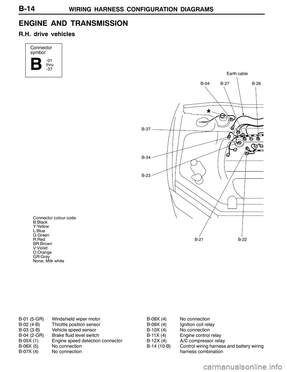
WIRING HARNESS CONFIGURATION DIAGRAMS
Connector
symbol
-01
thru
-37
B
Earth cable
B-27B-26B-04
B-22B-21
B-37
B-34
B-23
Connector colour code
B:Black
Y:Yellow
L:Blue
G:Green
R:Red
BR:Brown
V:Violet
O:Orange
GR:Gray
None: Milk white
B-14
ENGINE AND TRANSMISSION
R.H. drive vehicles
B-01 (5-GR) Windshield wiper motor
B-02 (4-B) Throttle position sensor
B-03 (3-B) Vehicle speed sensor
B-04 (2-GR) Brake fluid level switch
B-05X (1) Engine speed detection connector
B-06X (5) No connection
B-07X (4) No connectionB-08X (4) No connection
B-09X (4) Ignition coil relay
B-10X (4) No connection
B-11X (4) Engine control relay
B-12X (4) A/C compressor relay
B-14 (10-B) Control wiring harness and battery wiring
harness combination
Page 114 of 1449
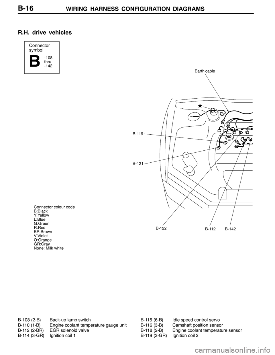
WIRING HARNESS CONFIGURATION DIAGRAMS
Connector
symbol
-108
thru
-142
B
Earth cable
B-119
B-121
B-112B-122B-142
Connector colour code
B:Black
Y:Yellow
L:Blue
G:Green
R:Red
BR:Brown
V:Violet
O:Orange
GR:Gray
None: Milk white
B-16
R.H. drive vehicles
B-108 (2-B) Back-up lamp switch
B-110 (1-B) Engine coolant temperature gauge unit
B-112 (2-BR) EGR solenoid valve
B-114 (3-GR) Ignition coil 1B-115 (6-B) Idle speed control servo
B-116 (3-B) Camshaft position sensor
B-118 (2-B) Engine coolant temperature sensor
B-119 (3-GR) Ignition coil 2
Page 118 of 1449
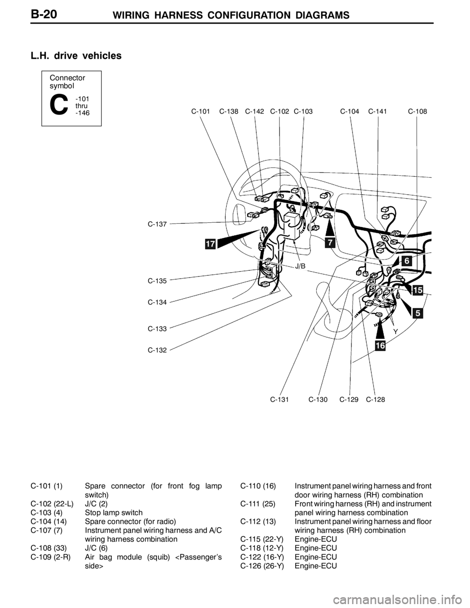
WIRING HARNESS CONFIGURATION DIAGRAMS
Connector
symbol
-101
thru
-146
C
C-137
C-135
C-134
C-133
C-132
C-131C-130C-129C-128
C-141C-104C-103C-102C-142C-138C-101C-108
5
6
7
15
16
17
J/B
Y
B-20
L.H. drive vehicles
C-101 (1) Spare connector (for front fog lamp
switch)
C-102 (22-L) J/C (2)
C-103 (4) Stop lamp switch
C-104 (14) Spare connector (for radio)
C-107 (7) Instrument panel wiring harness and A/C
wiring harness combination
C-108 (33) J/C (6)
C-109 (2-R) Air bag module (squib)
door wiring harness (RH) combination
C-111 (25) Front wiring harness (RH) and instrument
panel wiring harness combination
C-112 (13) Instrument panel wiring harness and floor
wiring harness (RH) combination
C-115 (22-Y) Engine-ECU
C-118 (12-Y) Engine-ECU
C-122 (16-Y) Engine-ECU
C-126 (26-Y) Engine-ECU
Page 124 of 1449
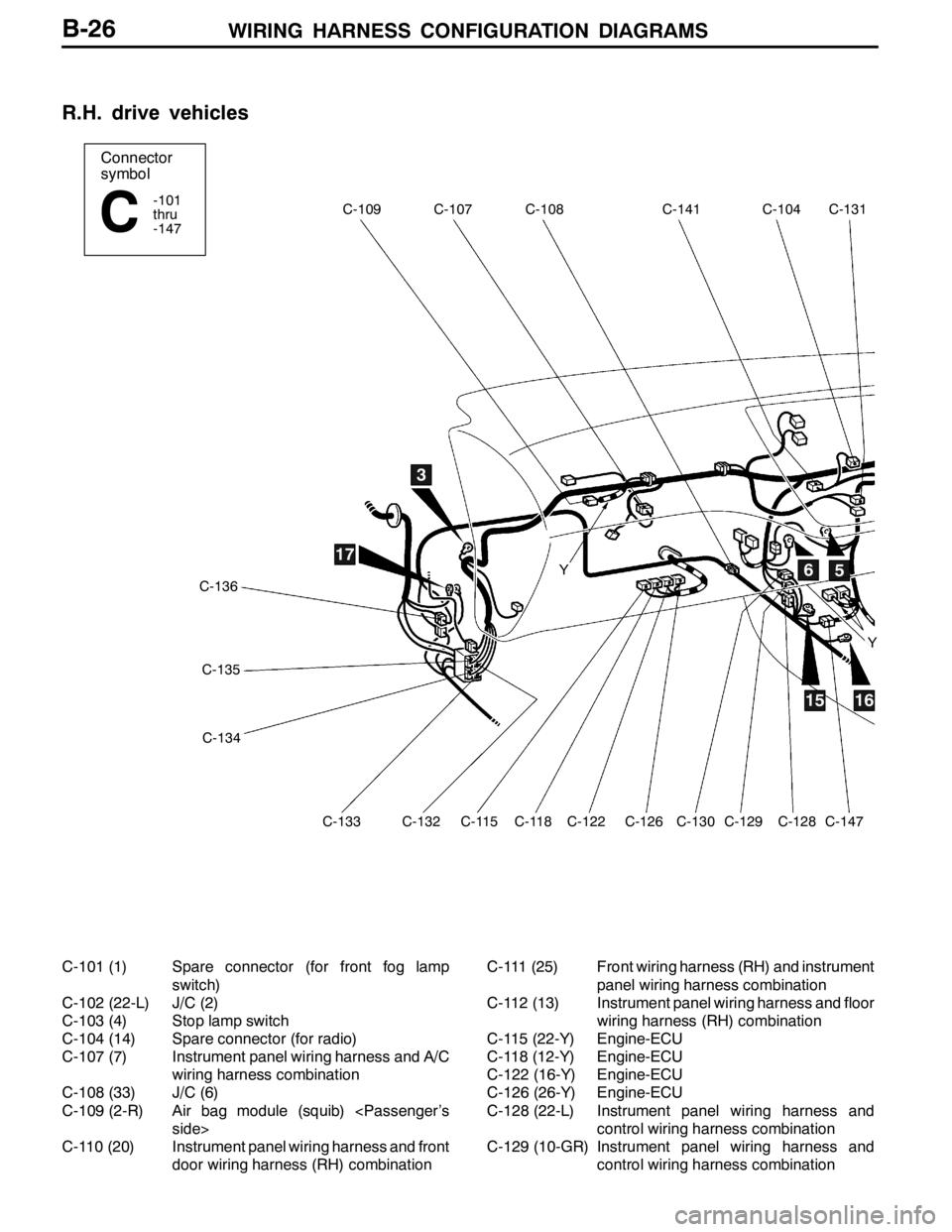
WIRING HARNESS CONFIGURATION DIAGRAMS
Connector
symbol
-101
thru
-147
C
C-109C-107C-108C-141C-104C-131
C-136
C-135
C-134
C-133C-132C-115C-118C-122C-126C-130C-129C-128C-147
3
56
1516
17Y
Y
B-26
R.H. drive vehicles
C-101 (1) Spare connector (for front fog lamp
switch)
C-102 (22-L) J/C (2)
C-103 (4) Stop lamp switch
C-104 (14) Spare connector (for radio)
C-107 (7) Instrument panel wiring harness and A/C
wiring harness combination
C-108 (33) J/C (6)
C-109 (2-R) Air bag module (squib)
C-110 (20) Instrument panel wiring harness and front
door wiring harness (RH) combinationC-111 (25) Front wiring harness (RH) and instrument
panel wiring harness combination
C-112 (13) Instrument panel wiring harness and floor
wiring harness (RH) combination
C-115 (22-Y) Engine-ECU
C-118 (12-Y) Engine-ECU
C-122 (16-Y) Engine-ECU
C-126 (26-Y) Engine-ECU
C-128 (22-L) Instrument panel wiring harness and
control wiring harness combination
C-129 (10-GR) Instrument panel wiring harness and
control wiring harness combination