lock MITSUBISHI LANCER EVOLUTION 2007 Service User Guide
[x] Cancel search | Manufacturer: MITSUBISHI, Model Year: 2007, Model line: LANCER EVOLUTION, Model: MITSUBISHI LANCER EVOLUTION 2007Pages: 1449, PDF Size: 56.82 MB
Page 116 of 1449
WIRING HARNESS CONFIGURATION DIAGRAMS
Connector
symbol
-01
thru
-45
C
C-29
C-05C-04C-03C-32C-02C-01
C-36
C-26
C-24
C-45
C-23C-22C-42C-41C-21
67
5
16
17
15
J/B
Y
B-18
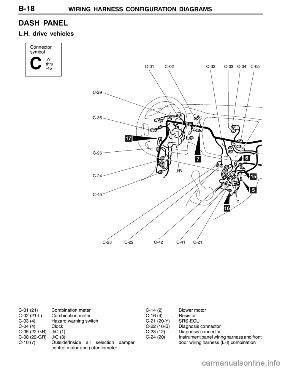
DASH PANEL
L.H. drive vehicles
C-01 (21) Combination meter
C-02 (21-L) Combination meter
C-03 (4) Hazard warning switch
C-04 (4) Clock
C-05 (22-GR) J/C (1)
C-08 (22-GR) J/C (3)
C-10 (7) Outside/Inside air selection damper
control motor and potentiometerC-14 (2) Blower motor
C-16 (4) Resistor
C-21 (20-Y) SRS-ECU
C-22 (16-B) Diagnosis connector
C-23 (12) Diagnosis connector
C-24 (20) Instrument panel wiring harness and front
door wiring harness (LH) combination
Page 120 of 1449
WIRING HARNESS CONFIGURATION DIAGRAMS
Connector
symbol
-201
thru
-230
CSTEERING COLUMN
C-207
C-206
C-205C-204C-230C-203C-202C-201 Y
Connector colour code
B:Black
Y:Yellow
L:Blue
G:Green
R:Red
BR:Brown
V:Violet
O:Orange
GR:Gray
None: Milk white
B-22
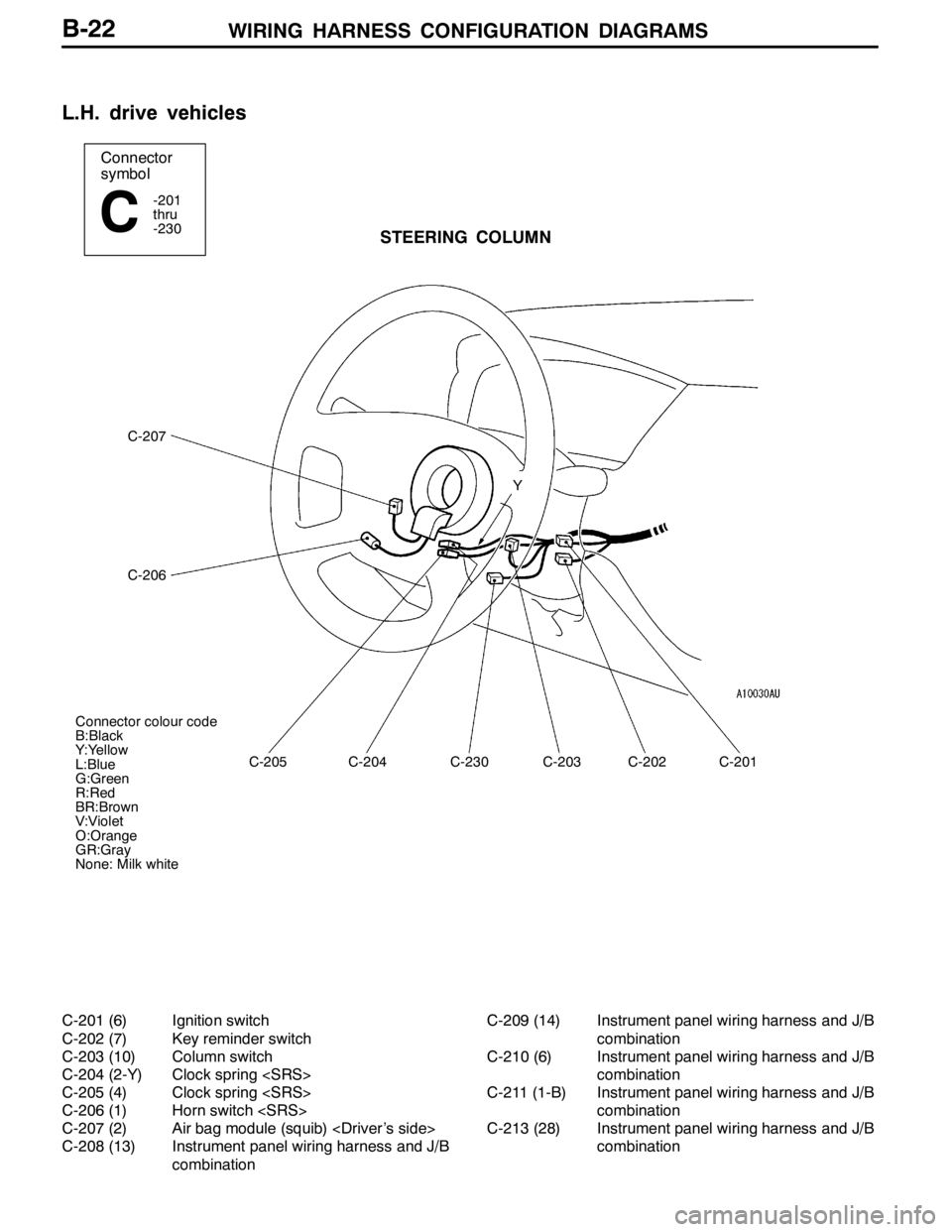
L.H. drive vehicles
C-201 (6) Ignition switch
C-202 (7) Key reminder switch
C-203 (10) Column switch
C-204 (2-Y) Clock spring
C-205 (4) Clock spring
C-206 (1) Horn switch
C-207 (2) Air bag module (squib)
C-208 (13) Instrument panel wiring harness and J/B
combinationC-209 (14) Instrument panel wiring harness and J/B
combination
C-210 (6) Instrument panel wiring harness and J/B
combination
C-211 (1-B) Instrument panel wiring harness and J/B
combination
C-213 (28) Instrument panel wiring harness and J/B
combination
Page 121 of 1449
WIRING HARNESS CONFIGURATION DIAGRAMS
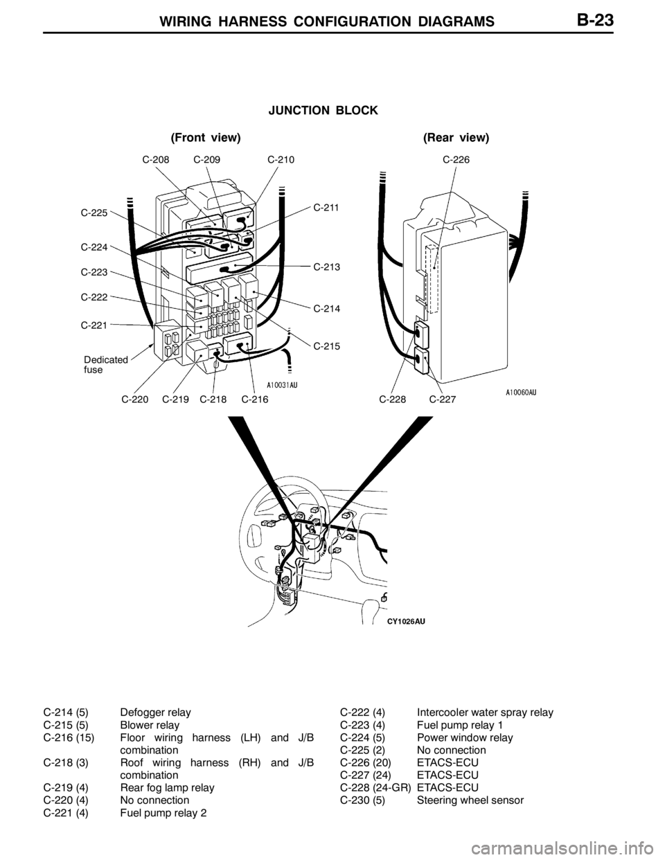
JUNCTION BLOCK
(Front view)(Rear view)
Dedicated
fuse
C-208C-209C-210C-226
C-220C-219C-218C-216C-228C-227
C-211
C-213
C-214
C-215
C-225
C-224
C-223
C-222
C-221
B-23
C-214 (5) Defogger relay
C-215 (5) Blower relay
C-216 (15) Floor wiring harness (LH) and J/B
combination
C-218 (3) Roof wiring harness (RH) and J/B
combination
C-219 (4) Rear fog lamp relay
C-220 (4) No connection
C-221 (4) Fuel pump relay 2C-222 (4) Intercooler water spray relay
C-223 (4) Fuel pump relay 1
C-224 (5) Power window relay
C-225 (2) No connection
C-226 (20) ETACS-ECU
C-227 (24) ETACS-ECU
C-228 (24-GR) ETACS-ECU
C-230 (5) Steering wheel sensor
Page 122 of 1449
WIRING HARNESS CONFIGURATION DIAGRAMS
Connector
symbol
-01
thru
-46
C
C-46
C-24
C-04C-32C-03C-05C-28C-10
C-14C-16C-44C-43C-35C-41C-21
15
16
17
3
56Y
Y
B-24
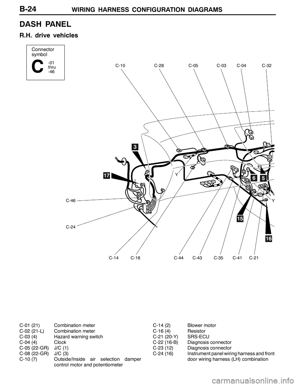
DASH PANEL
R.H. drive vehicles
C-01 (21) Combination meter
C-02 (21-L) Combination meter
C-03 (4) Hazard warning switch
C-04 (4) Clock
C-05 (22-GR) J/C (1)
C-08 (22-GR) J/C (3)
C-10 (7) Outside/Inside air selection damper
control motor and potentiometerC-14 (2) Blower motor
C-16 (4) Resistor
C-21 (20-Y) SRS-ECU
C-22 (16-B) Diagnosis connector
C-23 (12) Diagnosis connector
C-24 (16) Instrument panel wiring harness and front
door wiring harness (LH) combination
Page 126 of 1449
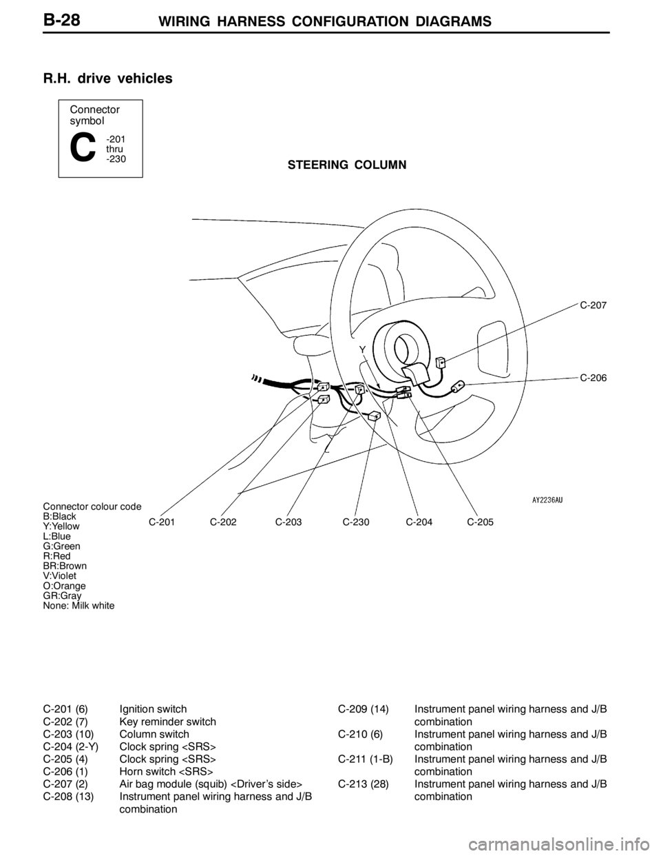
WIRING HARNESS CONFIGURATION DIAGRAMS
Connector colour code
B:Black
Y:Yellow
L:Blue
G:Green
R:Red
BR:Brown
V:Violet
O:Orange
GR:Gray
None: Milk white
Connector
symbol
-201
thru
-230
CSTEERING COLUMN
C-201
C-207
C-206
C-202C-203C-230C-204C-205 Y
B-28
R.H. drive vehicles
C-201 (6) Ignition switch
C-202 (7) Key reminder switch
C-203 (10) Column switch
C-204 (2-Y) Clock spring
C-205 (4) Clock spring
C-206 (1) Horn switch
C-207 (2) Air bag module (squib)
C-208 (13) Instrument panel wiring harness and J/B
combinationC-209 (14) Instrument panel wiring harness and J/B
combination
C-210 (6) Instrument panel wiring harness and J/B
combination
C-211 (1-B) Instrument panel wiring harness and J/B
combination
C-213 (28) Instrument panel wiring harness and J/B
combination
Page 127 of 1449
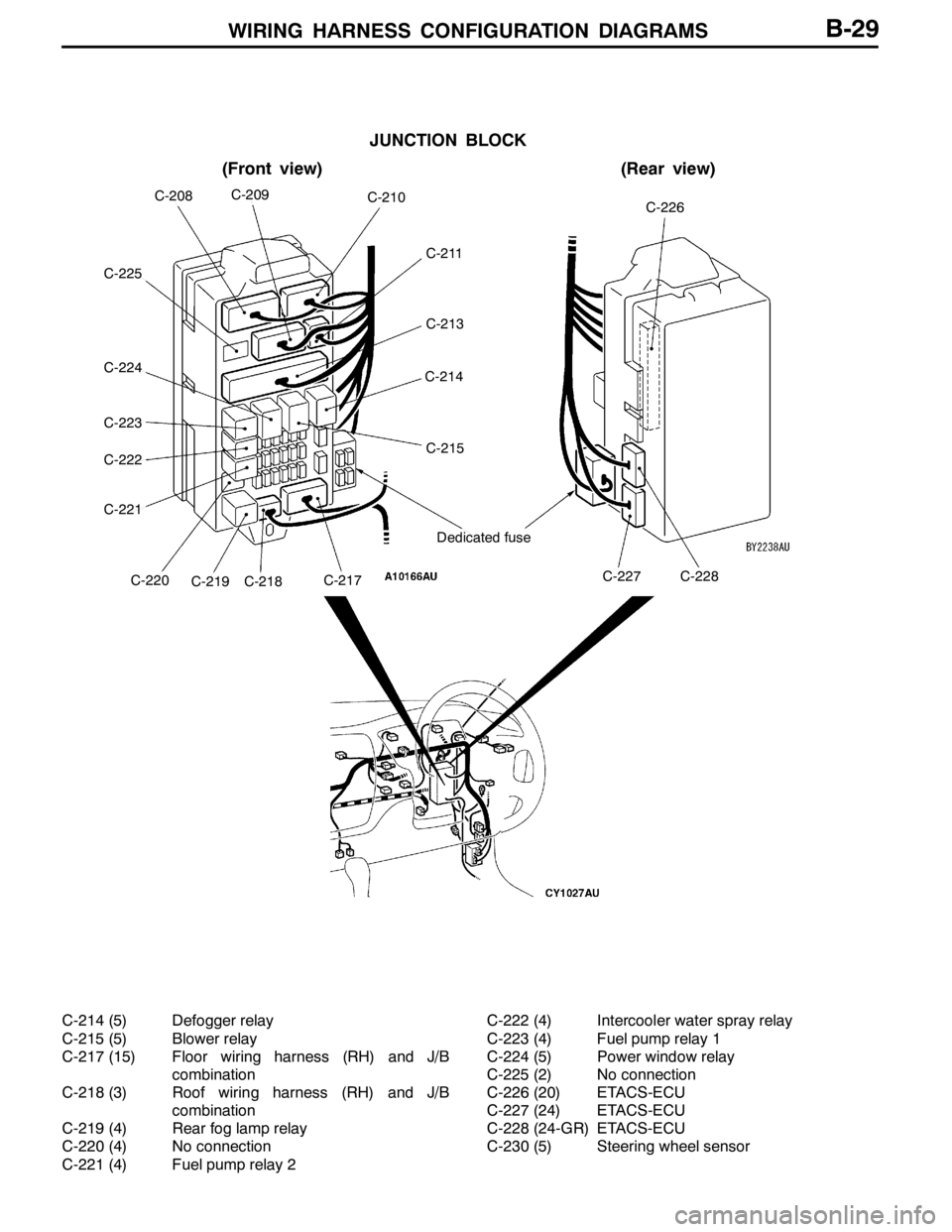
WIRING HARNESS CONFIGURATION DIAGRAMS
JUNCTION BLOCK
(Front view)(Rear view)
Dedicated fuse
C-226C-208C-209C-210
C-211
C-213
C-214
C-215
C-227C-228C-217C-218C-219C-220
C-222
C-221
C-223
C-224
C-225
B-29
C-214 (5) Defogger relay
C-215 (5) Blower relay
C-217 (15) Floor wiring harness (RH) and J/B
combination
C-218 (3) Roof wiring harness (RH) and J/B
combination
C-219 (4) Rear fog lamp relay
C-220 (4) No connection
C-221 (4) Fuel pump relay 2C-222 (4) Intercooler water spray relay
C-223 (4) Fuel pump relay 1
C-224 (5) Power window relay
C-225 (2) No connection
C-226 (20) ETACS-ECU
C-227 (24) ETACS-ECU
C-228 (24-GR) ETACS-ECU
C-230 (5) Steering wheel sensor
Page 132 of 1449
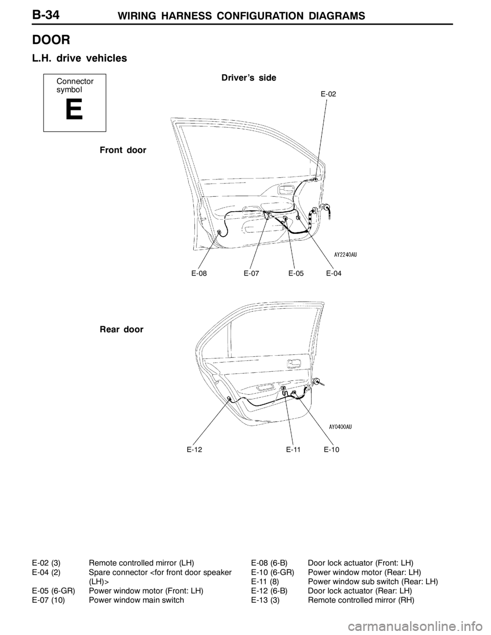
WIRING HARNESS CONFIGURATION DIAGRAMS
Connector
symbol
E
Driver’s side
Front door
Rear door
E-02
E-08E-07E-05E-04
E-12E-11E-10
B-34
DOOR
L.H. drive vehicles
E-02 (3) Remote controlled mirror (LH)
E-04 (2) Spare connector
E-05 (6-GR) Power window motor (Front: LH)
E-07 (10) Power window main switchE-08 (6-B) Door lock actuator (Front: LH)
E-10 (6-GR) Power window motor (Rear: LH)
E-11 (8) Power window sub switch (Rear: LH)
E-12 (6-B) Door lock actuator (Rear: LH)
E-13 (3) Remote controlled mirror (RH)
Page 133 of 1449
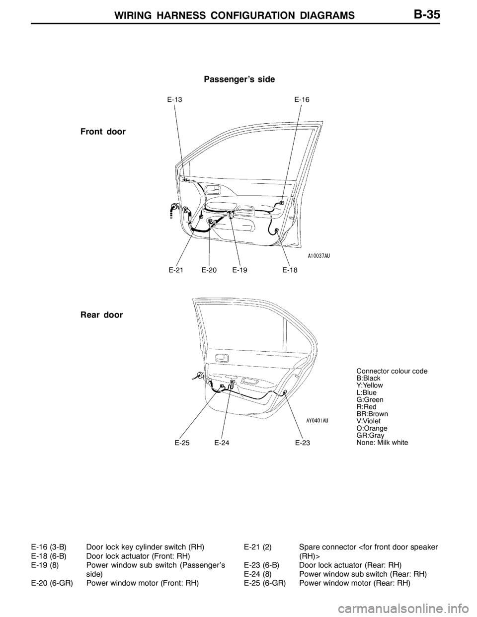
WIRING HARNESS CONFIGURATION DIAGRAMS
Passenger’s side
Front door
Rear door
E-13E-16
E-21E-20E-19E-18
E-25E-24E-23
Connector colour code
B:Black
Y:Yellow
L:Blue
G:Green
R:Red
BR:Brown
V:Violet
O:Orange
GR:Gray
None: Milk white
B-35
E-16 (3-B) Door lock key cylinder switch (RH)
E-18 (6-B) Door lock actuator (Front: RH)
E-19 (8) Power window sub switch (Passenger’s
side)
E-20 (6-GR) Power window motor (Front: RH)E-21 (2) Spare connector
E-23 (6-B) Door lock actuator (Rear: RH)
E-24 (8) Power window sub switch (Rear: RH)
E-25 (6-GR) Power window motor (Rear: RH)
Page 134 of 1449
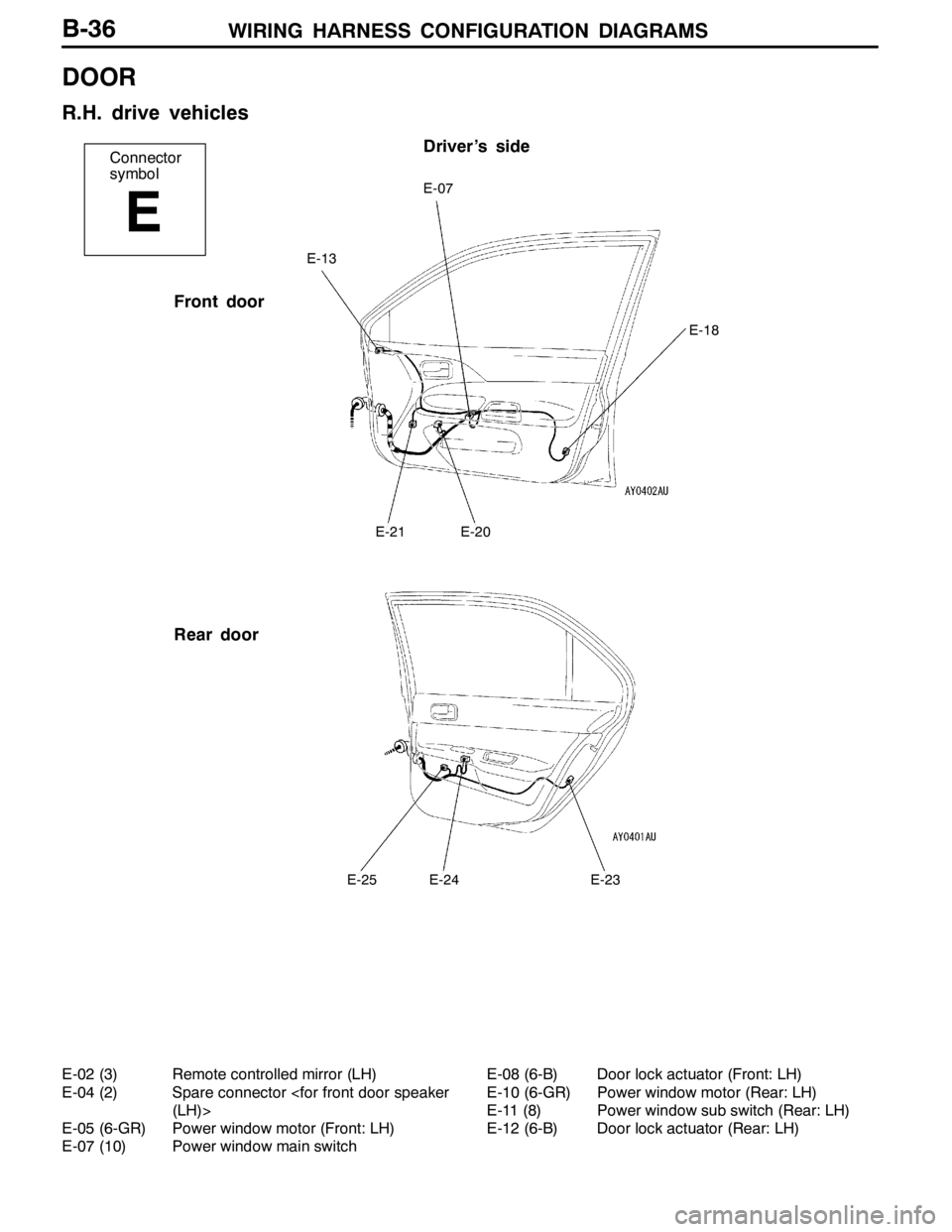
WIRING HARNESS CONFIGURATION DIAGRAMS
Connector
symbol
E
Driver’s side
Front door
Rear door
E-07
E-21E-20
E-18
E-13
E-25E-24E-23
B-36
DOOR
R.H. drive vehicles
E-02 (3) Remote controlled mirror (LH)
E-04 (2) Spare connector
E-05 (6-GR) Power window motor (Front: LH)
E-07 (10) Power window main switchE-08 (6-B) Door lock actuator (Front: LH)
E-10 (6-GR) Power window motor (Rear: LH)
E-11 (8) Power window sub switch (Rear: LH)
E-12 (6-B) Door lock actuator (Rear: LH)
Page 135 of 1449
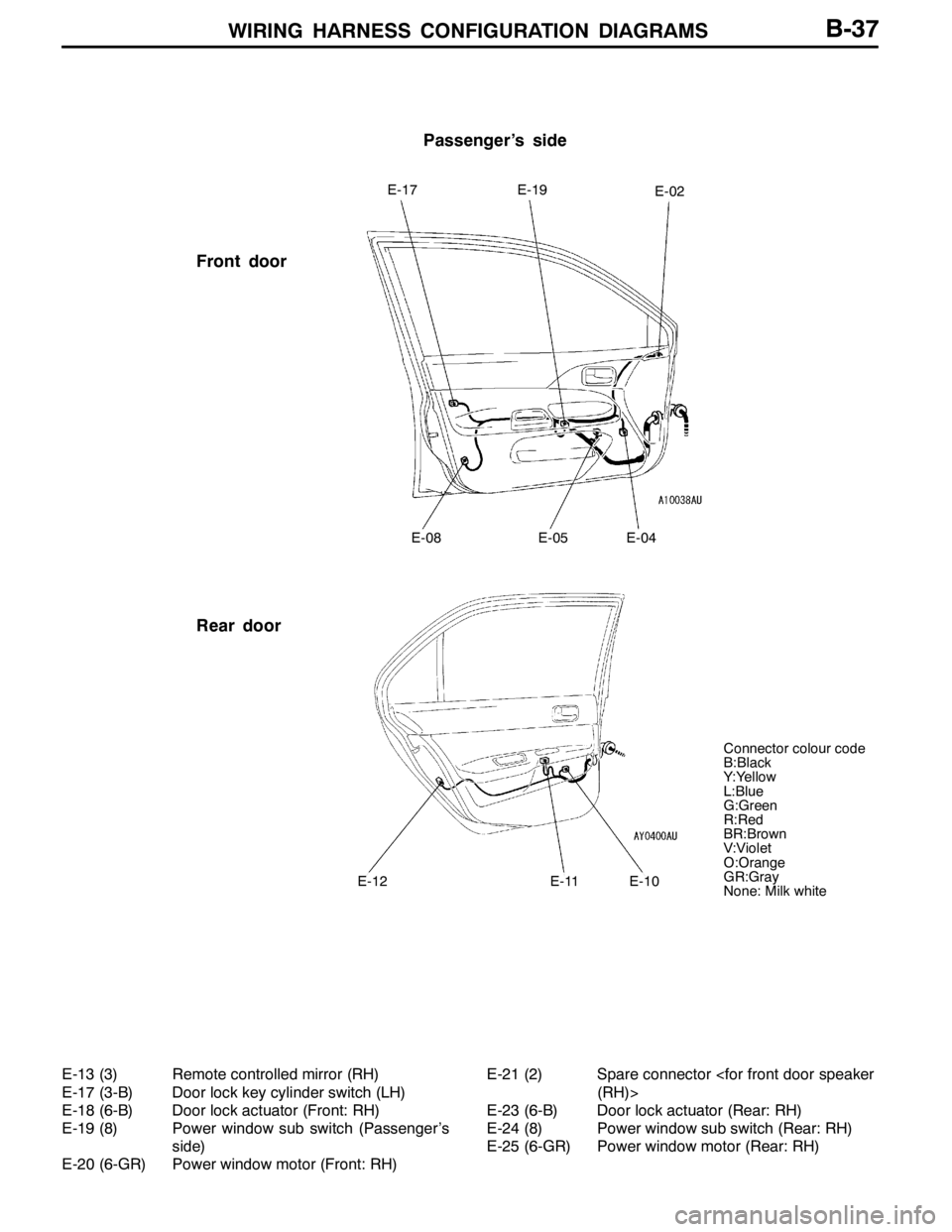
WIRING HARNESS CONFIGURATION DIAGRAMS
Passenger’s side
Front door
Rear door
E-17E-19E-02
E-08E-05E-04
E-12E-11E-10
Connector colour code
B:Black
Y:Yellow
L:Blue
G:Green
R:Red
BR:Brown
V:Violet
O:Orange
GR:Gray
None: Milk white
B-37
E-13 (3) Remote controlled mirror (RH)
E-17 (3-B) Door lock key cylinder switch (LH)
E-18 (6-B) Door lock actuator (Front: RH)
E-19 (8) Power window sub switch (Passenger’s
side)
E-20 (6-GR) Power window motor (Front: RH)E-21 (2) Spare connector
E-23 (6-B) Door lock actuator (Rear: RH)
E-24 (8) Power window sub switch (Rear: RH)
E-25 (6-GR) Power window motor (Rear: RH)