change time MITSUBISHI LANCER EVOLUTION 2014 10.G User Guide
[x] Cancel search | Manufacturer: MITSUBISHI, Model Year: 2014, Model line: LANCER EVOLUTION, Model: MITSUBISHI LANCER EVOLUTION 2014 10.GPages: 338, PDF Size: 40.99 MB
Page 118 of 338
Manual transaxle (if so equipped)
Features and controls 5-57
5
N00512700139
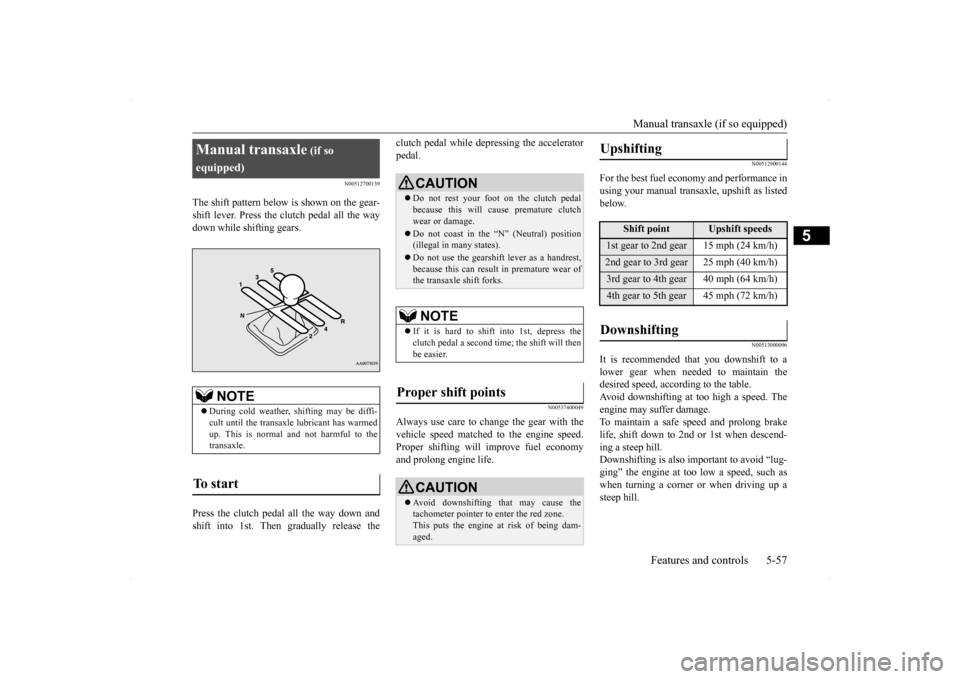
The shift pattern below is shown on the gear- shift lever. Press the clutch pedal all the way down while shifting gears. Press the clutch pedal all the way down and shift into 1st. Then gradually release the
clutch pedal while depressing the accelerator pedal.
N00537400049
Always use care to change the gear with thevehicle speed matched to the engine speed.Proper shifting will improve fuel economy and prolong engine life.
N00512900144
For the best fuel economy and performance in using your manual transaxle, upshift as listedbelow.
N00513000096
It is recommended that you downshift to alower gear when needed to maintain thedesired speed, according to the table.Avoid downshifting at too high a speed. The engine may suffer damage. To maintain a safe speed and prolong brakelife, shift down to 2nd or 1st when descend- ing a steep hill. Downshifting is also important to avoid “lug-ging” the engine at too low a speed, such as when turning a corner or when driving up a steep hill.
Manual transaxle
(if so
equipped)
NOTE
During cold weather, shifting may be diffi- cult until the transaxle lubricant has warmed up. This is normal and not harmful to thetransaxle.
To start
CAUTION Do not rest your foot on the clutch pedal because this will cause premature clutch wear or damage. Do not coast in the “N” (Neutral) position (illegal in many states). Do not use the gearshift lever as a handrest, because this can result in premature wear ofthe transaxle shift forks.NOTE
If it is hard to shift into 1st, depress the clutch pedal a second time; the shift will thenbe easier.
Proper shift points
CAUTION Avoid downshifting that may cause the tachometer pointer to enter the red zone. This puts the engine at risk of being dam- aged.
Upshifting
Shift point
Upshift speeds
1st gear to 2nd gear 15 mph (24 km/h)2nd gear to 3rd gear 25 mph (40 km/h)3rd gear to 4th gear 40 mph (64 km/h)4th gear to 5th gear 45 mph (72 km/h)Downshifting
BK0200800US.bo
ok 57 ページ 2013年2月14日 木曜日 午後2時28分
Page 126 of 338
Twin Clutch SST (Sportronic Shif
t Transmission) (if so equipped) Features and controls 5-65
5
Shifting can be performed even while the accelerator pedal is depressed. This allows the driver to enjoy sporty driving,such as quick cornering, by nimbly down- shifting to reduce vehicle speed just before entering a curve.
N00540600016
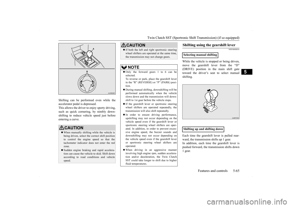
While the vehicle is stopped or being driven, move the gearshift lever from the “D” (DRIVE) position in the main shift gatetoward the driver’s seat to select manual shifting. Each time the gearshift lever is pulled rear- ward, the transmission shifts up 1 gear.In addition, each time the gearshift lever is pushed forward, the transmission shifts down 1 gear.
CAUTION When manually shifting while the vehicle is being driven, select the correct shift positionto control the engine speed so that the tachometer indicator does not enter the red zone. Sudden engine braking and rapid accelera- tion can cause the vehicle to skid. Shift downaccording to road conditions and vehicle speed.
If both the left and right sportronic steering wheel shifters are operated at the same time, the transmission may not change gears.NOTE
Only the forward gears 1 to 6 can be selected. To reverse or park, place the gearshift leverin the “R” (REVERSE) or “P” (PARK) posi- tion. During manual shifting, downshifting will be performed automatically when the vehicle slows down and the transmission will down-shift to 1st gear before the vehicle stops. If the gearshift lever or sportronic steering wheel shifters are operated repeatedly, the transmission will also shift repeatedly. In order to ensure driving performance, upshifting may not occur depending on the vehicle speed even if the gearshift lever orsportronic steering wheel shifters are oper- ated. In addition, in order to prevent exces- sive engine speed, the buzzer sounds anddownshifting may not occur depending on the vehicle speed even if the gearshift lever or sportronic steering wheel shifters are operated. When driving in an aggressive manner involving high engine rpm, sudden accelera- tion and/or deceleration, the Twin ClutchSST could take longer to shift due to higher fluid temperatures.CAUTION
Shifting using the gearshift lever
Selecting manual shifting Shifting up and shifting down�ç
BK0200800US.bo
ok 65 ページ 2013年2月14日 木曜日 午後2時28分
Page 133 of 338
S-AWC (Super-All Wheel Control) 5-72 Features and controls
5
and power drive distribution of the center dif- ferential.
N00541500012
The AYC is a system, with a left-right differ-ential limiting function and yaw control func-tion, that enhances cornering performance and stability during
cornering by controlling
the left-right drive power difference of therear wheels, the braking force of all four wheels, and the vehicle yaw moment.
The left-right differential limiting function is a function that enhances driving performance and vehicle stability by preventing idle spin-ning of a wheel when driving on slippery road surfaces or when the road surfaces of the left and right wheels are different. The yaw control function is a function that enhances vehicle cornering performance by controlling the drive power difference of theleft and right wheels
and the braking force
when the vehicle does not turn in response to steering input, such as when the steeringwheel is turned quickly or when driving on slippery road surfaces.
N00542401057
Select the control mode from the followingthree types to suit the driving conditions.
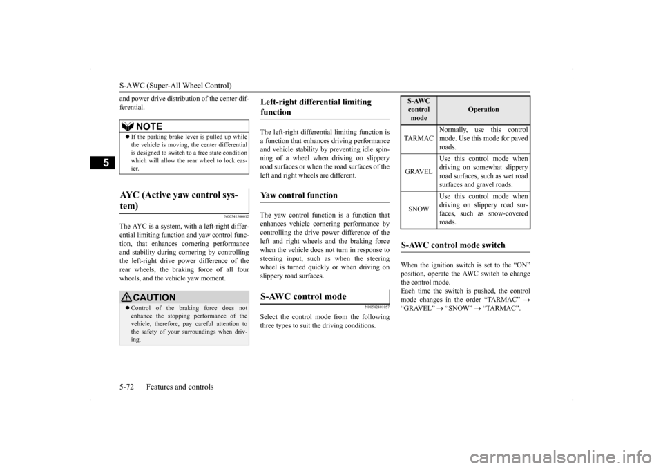
When the ignition switch is set to the “ON” position, operate the AWC switch to change the control mode.Each time the switch is pushed, the control mode changes in the order “TARMAC”
“GRAVEL”
“SNOW”
“TARMAC”.
NOTE
If the parking brake lever is pulled up while the vehicle is moving, the center differential is designed to switch to a free state conditionwhich will allow the rear wheel to lock eas- ier.
AYC (Active yaw control sys- tem)
CAUTION Control of the braking force does not enhance the stopping performance of the vehicle, therefore, pay careful attention to the safety of your surroundings when driv-ing.
Left-right differential limiting function Yaw control function S-AWC control mode
S-AWC control mode
Operation
TA R M A C
Normally, use this control mode. Use this mode for paved roads.
GRAVEL
Use this control mode when driving on somewhat slipperyroad surfaces, such as wet road surfaces and gravel roads.
SNOW
Use this control mode when driving on slippery road sur-faces, such as snow-covered roads.
S-AWC control mode switch
BK0200800US.bo
ok 72 ページ 2013年2月14日 木曜日 午後2時28分
Page 134 of 338
S-AWC (Super-All Wheel Control)
Features and controls 5-73
5
The currently selected control mode is dis- played on the multi-information display. In addition, when the control mode is changed, the selected mode appears on theinterrupt display screen of the information screen in the multi-information display. The control mode display will appear on theinformation screen for a few seconds, and then the original screen will return.
N00542500048
The S-AWC operation status can be displayedon the information screen in the multi-infor- mation display.To display the status, press the multi-informa- tion meter switch to change the information screen.Refer to “Information screen (when the igni- tion switch is “ON”)” on page 5-97.
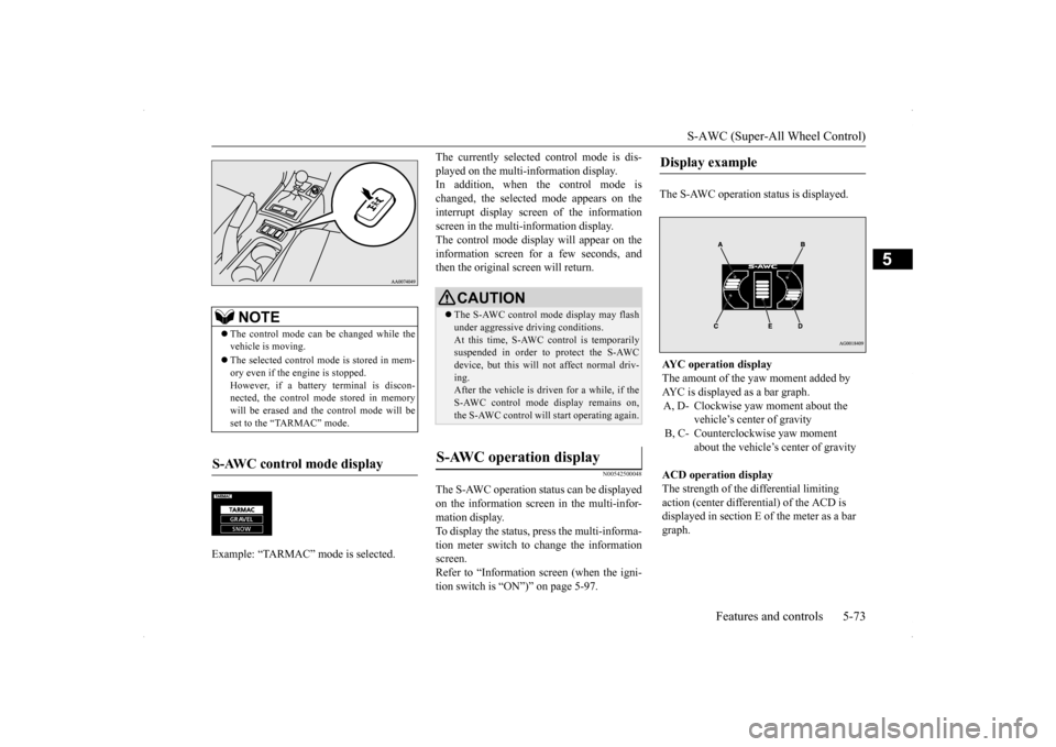
The S-AWC operation status is displayed.
NOTE
The control mode can be changed while the vehicle is moving. The selected control mode is stored in mem- ory even if the engine is stopped. However, if a battery terminal is discon-nected, the control mode stored in memory will be erased and the control mode will be set to the “TARMAC” mode.
S-AWC control mode display Example: “TARMAC” mode is selected.�ç
CAUTION The S-AWC control mode display may flash under aggressive driving conditions. At this time, S-AWC control is temporarily suspended in order to protect the S-AWCdevice, but this will not affect normal driv- ing. After the vehicle is driven for a while, if theS-AWC control mode display remains on, the S-AWC control will start operating again.
S-AWC operation display
Display example AYC operation display The amount of the yaw moment added by AYC is displayed as a bar graph.A, D- Clockwise yaw moment about the
vehicle’s center of gravity
B, C- Counterclockwise yaw moment
about the vehicle’s center of gravity
ACD operation display The strength of the differential limiting action (center differential) of the ACD is displayed in section E of the meter as a bar graph.
BK0200800US.bo
ok 73 ページ 2013年2月14日 木曜日 午後2時28分
Page 151 of 338
Instrument cluster 5-90 Features and controls
5
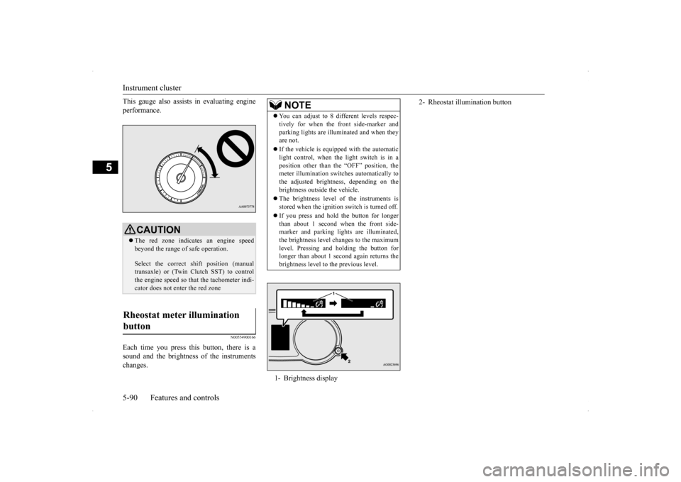
This gauge also assist
s in evaluating engine
performance.
N00554900166
Each time you press this button, there is a sound and the brightness of the instruments changes.
CAUTION The red zone indicates an engine speed beyond the range of safe operation. Select the correct shift position (manual transaxle) or (Twin Clutch SST) to control the engine speed so that the tachometer indi- cator does not enter the red zone
Rheostat meter illumination button
NOTE
You can adjust to 8 different levels respec- tively for when the front side-marker and parking lights are illuminated and when they are not. If the vehicle is equipped with the automatic light control, when the light switch is in a position other than the “OFF” position, themeter illumination switches automatically to the adjusted brightness, depending on the brightness outside the vehicle. The brightness level of the instruments is stored when the ignition switch is turned off. If you press and hold the button for longer than about 1 second when the front side-marker and parking lights are illuminated, the brightness level changes to the maximum level. Pressing and holding the button forlonger than about 1 second again returns the brightness level to the previous level.1- Brightness display
2- Rheostat illumination button
BK0200800US.bo
ok 90 ページ 2013年2月14日 木曜日 午後2時28分
Page 153 of 338
Multi-information display 5-92 Features and controls
5
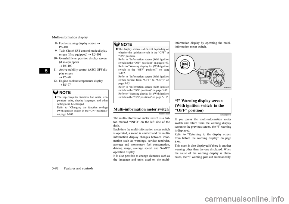
N00555100165
The multi-information meter switch is a but- ton marked “INFO” on the left side of the dash. Each time the multi-information meter switchis operated, a sound is emitted and the multi- information display changes between infor- mation such as warnings, service reminder,average and momentary fuel consumption, driving range, average speed, and S-AWC operation display.It is also possible to change elements such as the language and units used on the multi-
information display by operating the multi- information meter switch.
N00555200078
If you press the multi-information meter switch and return from the warning display screen to the previous screen, the “!” warningis displayed. Refer to “Returning to the display screen from before the warning display” on page5-94. This mark is also displayed if there is another warning other than the one displayed. Whenthe cause of the warning display is elimi- nated, the “!” warning goes out automatically.
8- Fuel remaining display screen
P.5-101
9- Twin Clutch SST control mode display
screen (if so equipped)
P.5-101
10- Gearshift lever position display screen
(if so equipped) P.5-100
11- Active stability control (ASC) OFF dis-
play screen P.5-78
12- Engine coolant temperature display
P.5-97NOTE
The trip computer function fuel units, tem- perature units, display language, and other settings can be changed.Refer to “Changing the function settings (With ignition switch in the “ON” position)” on page 5-103.
The display screen is different depending on whether the ignition switch in the “OFF” or “ON” position. Refer to “Information screen (With ignition switch in the “OFF” position)” on page 5-93.Refer to “Warning displa
y list (With ignition
switch in the “OFF” position)” on page 5-112.Refer to “Information screen (With ignition switch turned from “OFF” to “ON”)” on page 5-95.Refer to “Information screen (With ignition switch in the “ON” position)” on page 5-97. Refer to “Warning displa
y list (With ignition
switch in the “ON” position)” on page 5-115.
Multi-information meter switch
NOTE
“!” Warning display screen (With ignition switch in the “OFF” position)
BK0200800US.bo
ok 92 ページ 2013年2月14日 木曜日 午後2時28分
Page 156 of 338
Multi-information display
Features and controls 5-95
5
When the “!” warning is displayed, if you lightly press the multi-information meter switch a few times, the warning display screen you switched from is redisplayed. Refer to “Information screen (With ignition switch in the “OFF” position)” on page 5-93.
N00559700114
If any of the doors or the trunk lid is not com-pletely closed, this displays the open door ortrunk lid.
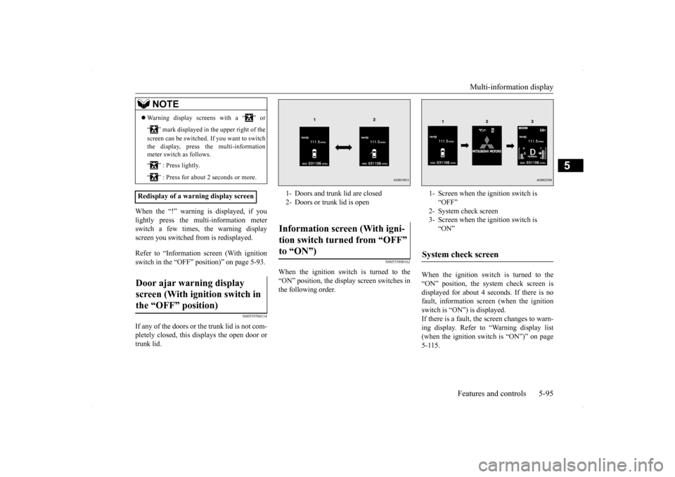
N00555800162
When the ignition switch is turned to the“ON” position, the display screen switches inthe following order.
When the ignition switch is turned to the “ON” position, the system check screen is displayed for about 4 seconds. If there is no fault, information screen (when the ignitionswitch is “ON”) is displayed. If there is a fault, the
screen changes to warn-
ing display. Refer to “Warning display list(when the ignition switch is “ON”)” on page 5-115.
NOTE
Warning display screens with a “ ” or “ ” mark displayed in the upper right of the screen can be switched. If you want to switch the display, press the multi-information meter switch as follows. “ ” : Press lightly. “ ” : Press for about 2 seconds or more.
Redisplay of a warning display screenDoor ajar warning display screen (With ignition switch in the “OFF” position)
1- Doors and trunk lid are closed 2- Doors or trunk lid is openInformation screen (With igni- tion switch turned from “OFF” to “ON”)
1- Screen when the ignition switch is
“OFF”
2- System check screen 3- Screen when the ignition switch is
“ON”
System check screen
BK0200800US.bo
ok 95 ページ 2013年2月14日 木曜日 午後2時28分
Page 162 of 338
Multi-information display
Features and controls 5-101
5
N00556500081
Shows the temperature outside the vehicle.
N00545100016
The operation status of the Twin Clutch SST control mode is displayed. Refer to “Twin Clutch SST control mode” on page 5-62.
N00556600109
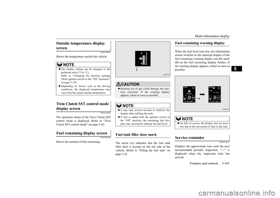
Shows the amount of fuel remaining.
The arrow (A) indicates that the fuel tank filler door is located on the left side of the vehicle. (Refer to “Filling the fuel tank” on page 3-4)
When the fuel level runs low, the information screen switches to the interrupt display of thefuel remaining warning display and the mark (B) on the fuel remaining display flashes. If the warning display appears, refuel as soon aspossible.
N00556700197
Displays the approximate time until the nextrecommended periodic inspection. “---” isdisplayed when the inspection time has arrived.
Outside temperature display screen
NOTE
The display setting can be changed to the preferred units (°F or °C).Refer to “Changing the function settings (With ignition switch in the “ON” position)” on page 5-103. Depending on factors such as the driving conditions, the displayed temperature mayvary from the actual outside temperature.
Twin Clutch SST control mode display screen Fuel remaining display screen
CAUTION Running out of gas could damage the cata- lytic converter. If the warning display appears, refuel as soon as possible.NOTE
It may take several seconds to stabilize the display after refilling the tank. If fuel is added with the ignition switch in the “ON” position, the remaining fuel dis- play may incorrectly indicate the fuel level.
Fuel tank filler door mark
Fuel remaining warning display
NOTE
On hills or curves, the display may be incor- rect due to the movement of fuel in the tank.
Service reminder
BK0200800US.book
101 ページ 2013年2月14日 木曜日 午後2時28分
Page 165 of 338
Multi-information display 5-104 Features and controls
5
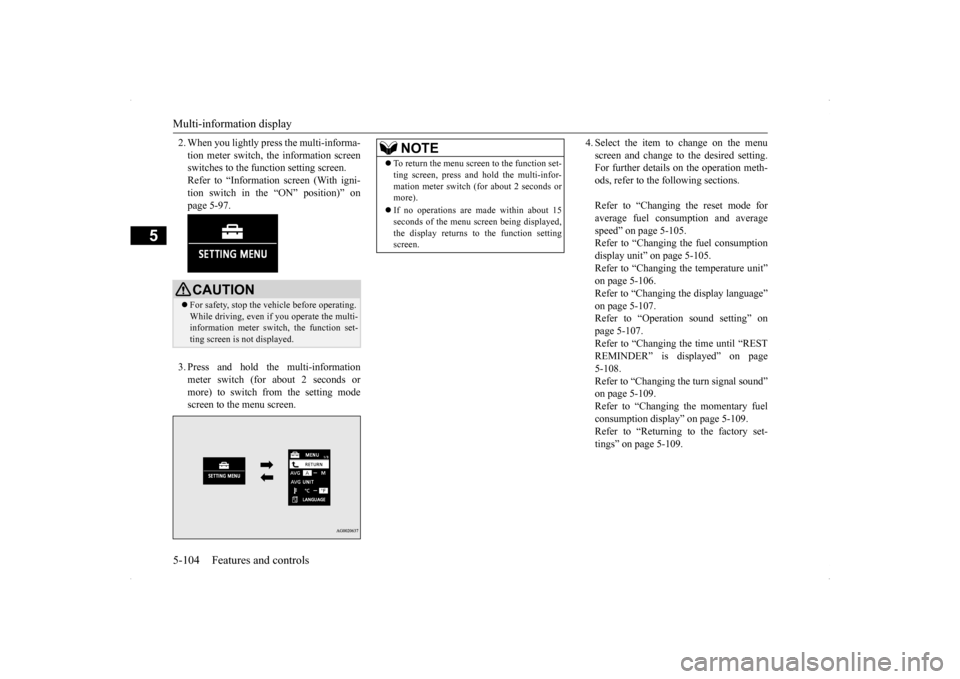
2. When you lightly press the multi-informa- tion meter switch, the information screen switches to the function setting screen. Refer to “Information screen (With igni-tion switch in the “ON” position)” on page 5-97. 3. Press and hold the multi-information meter switch (for about 2 seconds or more) to switch from the setting mode screen to the menu screen.
4. Select the item to change on the menu screen and change to the desired setting. For further details on the operation meth- ods, refer to the following sections. Refer to “Changing the reset mode for average fuel consumption and averagespeed” on page 5-105. Refer to “Changing the fuel consumption display unit” on page 5-105.Refer to “Changing the temperature unit”on page 5-106. Refer to “Changing the display language” on page 5-107.Refer to “Operation sound setting” on page 5-107. Refer to “Changing the time until “RESTREMINDER” is displayed” on page 5-108. Refer to “Changing the turn signal sound”on page 5-109. Refer to “Changing the momentary fuel consumption display” on page 5-109.Refer to “Returning to the factory set- tings” on page 5-109.
CAUTION For safety, stop the vehicle before operating. While driving, even if you operate the multi-information meter switch, the function set- ting screen is not displayed.
NOTE
To return the menu screen to the function set- ting screen, press and hold the multi-infor- mation meter switch (for about 2 seconds or more). If no operations are made within about 15 seconds of the menu screen being displayed, the display returns to the function settingscreen.
BK0200800US.book
104 ページ 2013年2月14日 木曜日 午後2時28分
Page 169 of 338
Multi-information display 5-108 Features and controls
5
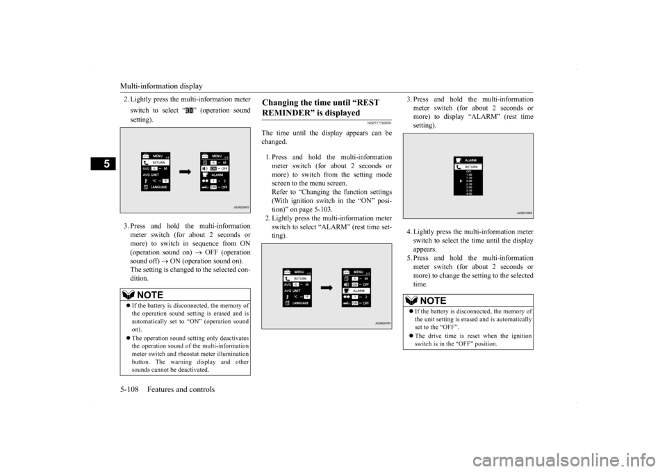
2. Lightly press the multi-information meter switch to select “ ” (operation sound setting). 3. Press and hold the multi-information meter switch (for about 2 seconds or more) to switch in sequence from ON (operation sound on)
OFF (operation
sound off)
ON (operation sound on).
The setting is changed to the selected con- dition.
N00557500091
The time until the display appears can be changed. 1. Press and hold the multi-information meter switch (for about 2 seconds ormore) to switch from the setting mode screen to the menu screen. Refer to “Changing the function settings(With ignition switch in the “ON” posi-tion)” on page 5-103. 2. Lightly press the multi-information meter switch to select “ALARM” (rest time set-ting).
3. Press and hold the multi-information meter switch (for about 2 seconds or more) to display “ALARM” (rest time setting). 4. Lightly press the multi-information meter switch to select the time until the displayappears.5. Press and hold the multi-information meter switch (for about 2 seconds or more) to change the setting to the selectedtime.
NOTE
If the battery is disconnected, the memory of the operation sound setting is erased and is automatically set to “ON” (operation sound on). The operation sound setting only deactivates the operation sound of the multi-informationmeter switch and rheostat meter illumination button. The warning display and other sounds cannot be deactivated.
Changing the time until “REST REMINDER” is displayed
NOTE
If the battery is disconnected, the memory of the unit setting is erased and is automatically set to the “OFF”. The drive time is reset when the ignition switch is in the “OFF” position.
BK0200800US.book
108 ページ 2013年2月14日 木曜日 午後2時28分