height MITSUBISHI LANCER EVOLUTION 2014 10.G Owners Manual
[x] Cancel search | Manufacturer: MITSUBISHI, Model Year: 2014, Model line: LANCER EVOLUTION, Model: MITSUBISHI LANCER EVOLUTION 2014 10.GPages: 338, PDF Size: 40.99 MB
Page 31 of 338
Head restraints 4-6 Seat and restraint systems
4
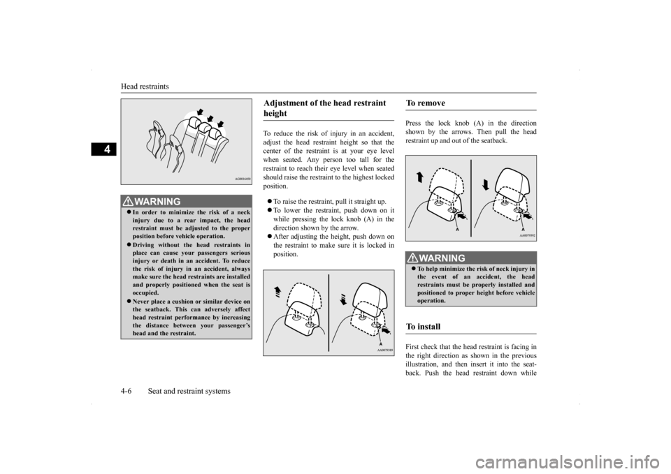
To reduce the risk of injury in an accident, adjust the head restraint height so that the center of the restraint is at your eye levelwhen seated. Any person too tall for the restraint to reach their eye level when seated should raise the restraint to the highest lockedposition. To raise the restraint, pull it straight up. To lower the restraint, push down on it while pressing the lock knob (A) in the direction shown by the arrow. After adjusting the height, push down on the restraint to make sure it is locked in position.
Press the lock knob (A) in the direction shown by the arrows. Then pull the headrestraint up and out of the seatback. First check that the head restraint is facing in the right direction as shown in the previousillustration, and then insert it into the seat- back. Push the head restraint down while
WA R N I N G In order to minimize the risk of a neck injury due to a rear impact, the head restraint must be adjusted to the properposition before vehicle operation. Driving without the head restraints in place can cause your passengers serious injury or death in an accident. To reduce the risk of injury in an accident, alwaysmake sure the head restraints are installed and properly positioned when the seat is occupied. Never place a cushion or similar device on the seatback. This can adversely affecthead restraint performance by increasing the distance between your passenger’s head and the restraint.
Adjustment of the head restraint height
To remove
WA R N I N G To help minimize the risk of neck injury in the event of an accident, the head restraints must be properly installed and positioned to proper height before vehicleoperation.
To i n s t a l l
BK0200800US.bo
ok 6 ページ 2013年2月14日 木曜日 午後2時28分
Page 38 of 338
Child restraint systems
Seat and restraint systems 4-13
4
Child restraint systems specifically designed for infants and small children are offered by several manufacturers. Choose only a child restraint system with a label certifying that itcomplies with Federal Motor Vehicle Safety Standard 213 (FMVSS 213) or Motor Vehicle Restraint Systems and Booster CushionsSafety Regulations (RSSR). Look for the manufacturer’s statement of compliance on the box and child restraint system itself. The child restraint system should be appropri- ate for your child’s weight and height, andshould properly fit your vehicle’s seat. For detail information, refer to the instruction manual accompanying the child restraint sys-tem. All children should be properly restrained in a restraint device that offers the maximum protection for their size and age.Be sure to check local, state, or provincial requirements for child size and age that may vary from the recommendations listed below. Children less than 1 year old and children less than 20 pounds (9 kg) MUST ride in a rear-facing child safety seat that MUST ONLY be used in the rear seat.
Children older than 1
year of age and who
weigh less than 40 pounds (18 kg) or who are less than 40 inches (100 cm) tall must be in a forward-facing restraint used onlyin the rear seat. Children who weigh more than 40 pounds (18 kg) or who are more than 40 inches(100 cm) tall, regardless of age, should use a suitable child seat or a booster seat (including a booster cushion) in the rearseat until the vehicle’s lap/shoulder beltfits them properly.
Guidelines for child restraint system selection
WA R N I N G All children must be seated in the rear seat, and properly restrained. Accident statistics show that children of all sizes and ages are safer when properlyrestrained in the rear seat, rather than in the front seat.
Any child who is too large to use a child restraint system should ride in the rear seat and wear the lap and shoulder belt properly. The shoulder belt must be posi- tioned over the shoulder and across thechest, not across their neck, and with the lap belt positioned low on the child’s hips, not across their stomach. If necessary, abooster seat (including a booster cushion) should be used to help achieve a proper seat belt fit. Follow the booster seat(including a booster cushion) manufac- turer’s instructions. Only use a booster seat (including a booster cushion) that iscertified as complying with Federal Motor Vehicle Safety Standards or Motor Vehicle Restraint Systems and Booster CushionsSafety Regulations. Never hold an infant or child in your arms or on your lap when riding in this vehicle, even when you are wearing your seat belt. Never place any part of the seat belt youare wearing around an infant or child. Failure to follow these simple instructions creates a risk of serious injury or death toyour child in the event of an accident or sudden stop.WA R N I N G
BK0200800US.bo
ok 13 ページ 2013年2月14日 木曜日 午後2時28分
Page 108 of 338
Parking brake
Features and controls 5-47
5
N00511400360
To park the vehicle, first bring it to a com- plete stop, fully engage the parking brake,and then move the gearshift lever to 1st (on a uphill) or “R” (Reverse) (on a downhill) posi- tion, for vehicles with a manual transaxle orset the gearshift lever to “P” (PARK) position on Twin Clutch SST vehicles.
When parking on a hill, apply the parking brake and turn the front wheels toward thecurb on a downhill grade, away from the curb on an uphill grade.
N00511500198
To adjust the steering wheel height, releasethe tilt lock lever while holding the steering wheel by hand, and raise or lower the steeringwheel to the desired height. After adjustment, securely lock the lever by pulling it upward.
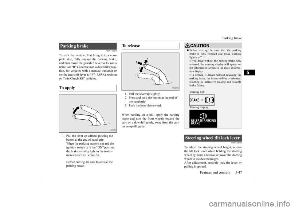
Parking brake To apply 1- Pull the lever up without pushing the
button at the end of hand grip. When the parking brake is set and the ignition switch is in the “ON” position, the brake warning light in the instru-ment cluster will come on. Before driving, be sure to release the parking brake.
To release 1- Pull the lever up slightly. 2- Press and hold the button at the end of
the hand grip.
3- Push the lever downward.
CAUTION Before driving, be sure that the parking brake is fully released and brake warning light is off. If you drive without the parking brake fully released, the warning display will appear onthe information screen in the multi-informa- tion display. If a vehicle is driven without releasing theparking brake, the brakes will be overheated, resulting in ineffective braking and possible brake failure. Warning light Warning display
Steering wheel tilt lock lever
BK0200800US.bo
ok 47 ページ 2013年2月14日 木曜日 午後2時28分
Page 284 of 338
Tires
Vehicle care and maintenance 9-13
9
Recommended inflation pressure: the inflation pressure for optimum tire perfor- mance. Intended outboard sidewall: • The sidewall that contains a whitewall, bears white lettering or bears manufac- turer, brand, and/or model name moldingthat is higher or deeper than the same molding on the other sidewall of the tire, or• The outward facing sidewall of an asym-metrical tire that has a particular side that must always face outward when mounted on a vehicle.
Passenger car tire: a tire intended for use on passenger cars, multipurpose passen- ger vehicles, and trucks, that have a grossvehicle weight rating (GVWR) of 10,000 pounds or less. Light truck (LT) tire: a tire designated by its manufacturer as primarily intended for use on lightweight trucks or multipurpose passenger vehicles. Tread: portion of a tire that comes into contact with the road. Tread rib: a tread section running circum- ferentially around a tire. Tread separation: pulling away of the tread from the tire carcass. Carcass: the tire structure, except tread and sidewall rubber which, when inflated, bears the load.
Sidewall: portion of a tire between the tread and bead. Section width: the li
near distance between
the exteriors of the sidewalls of aninflated tire, excluding elevations due to labeling, decoration, or protective bands. Bead: the part of the tire that is made of steel wires, wrapped or reinforced by ply cords and that is shaped to fit the rim. Ply: a layer of rubber-coated parallel cords. Cord: the strands forming the plies in the tire. Rim: a metal support for a tire or a tire and tube assembly upon which the tire beads are seated. Rim diameter: nominal diameter of the bead seat. Groove: the space between two adjacent tread ribs.
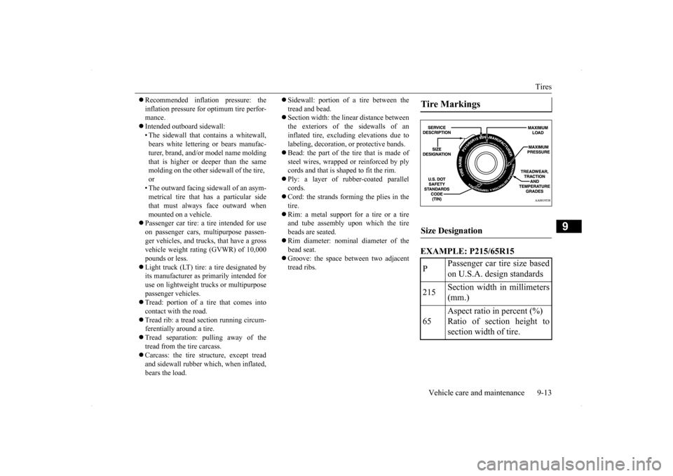
EXAMPLE: P215/65R15Tire Markings Size Designation P
Passenger car tire size based on U.S.A. design standards
215
Section width in millimeters (mm.)
65
Aspect ratio in percent (%) Ratio of section height to section width of tire.
BK0200800US.bo
ok 13 ページ 2013年2月14日 木曜日 午後2時28分
Page 326 of 338
Vehicle dimensions
Specifications 11-3
11
N01148100560
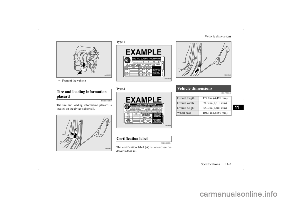
The tire and loading information placard is located on the driver’s door sill.
Ty p e 1 Ty p e 2
N01148200213
The certification label (A) is located on the driver’s door sill.
N01147500352
* - Front of the vehicleTire and loading information placard
Certification label
Vehicle dimensions Overall length 177.0 in (4,495 mm)Overall width 71.3 in (1,810 mm) Overall height 58.3 in (1,480 mm)Wheel base 104.3 in (2,650 mm)
BK0200800US.bo
ok 3 ページ 2013年2月14日 木曜日 午後2時28分