MITSUBISHI LANCER EVOLUTION IX 2005 Workshop Manual
LANCER EVOLUTION IX 2005
MITSUBISHI
MITSUBISHI
https://www.carmanualsonline.info/img/19/57323/w960_57323-0.png
MITSUBISHI LANCER EVOLUTION IX 2005 Workshop Manual
Trending: oil temperature, gas type, wiring diagram, differential, alternator, jack points, alternator belt
Page 151 of 364
1-1
Section 1
Layout Diagrams
CONTENTS
General Layout Diagram ........................1-3
Engine Compartment .............................1-4
Engine / Transmission ...........................1-6
Instrument Panel...................................1-10Floor / Roof ...........................................1-16
Door .......................................................1-18
Boot Compartment ...............................1-20
Page 152 of 364
Page 153 of 364
LAYOUT DIAGRAMS - GENERAL LAYOUT DIAGRAM1-3
Front
harness (RH)Control panelInstrument
panel harnessRoof harness
Floor harness (RH)
Battery
harness
Front harness (LH)
Front door
harness *Floor
harness (LH)Fuel harnessRear door harness *
Note :
1. This diagram shows the main wiring harnesses only.
2. The * symbol indicates that the harness is also fitted on the right-hand side.
General Layout Diagram
Page 154 of 364
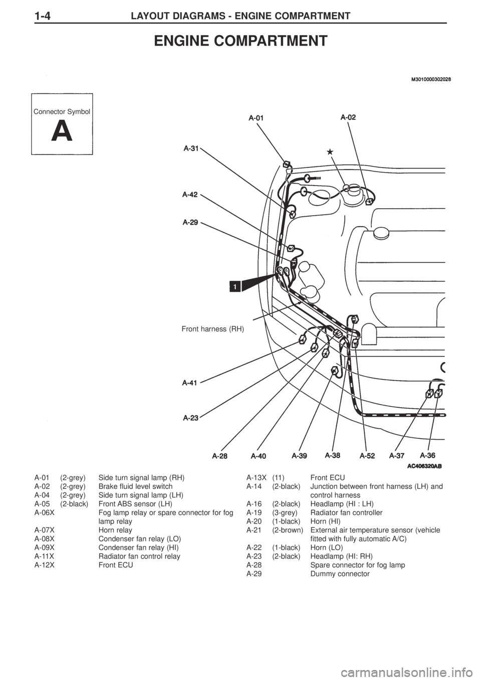
LAYOUT DIAGRAMS - ENGINE COMPARTMENT1-4
A-01 (2-grey) Side turn signal lamp (RH)
A-02 (2-grey) Brake fluid level switch
A-04 (2-grey) Side turn signal lamp (LH)
A-05 (2-black) Front ABS sensor (LH)
A-06X Fog lamp relay or spare connector for fog
lamp relay
A-07X Horn relay
A-08X Condenser fan relay (LO)
A-09X Condenser fan relay (HI)
A-11X Radiator fan control relay
A-12X Front ECUA-13X (11) Front ECU
A-14 (2-black) Junction between front harness (LH) and
control harness
A-16 (2-black) Headlamp (HI : LH)
A-19 (3-grey) Radiator fan controller
A-20 (1-black) Horn (HI)
A-21 (2-brown) External air temperature sensor (vehicle
fitted with fully automatic A/C)
A-22 (1-black) Horn (LO)
A-23 (2-black) Headlamp (HI: RH)
A-28 Spare connector for fog lamp
A-29 Dummy connector
ENGINE COMPARTMENT
Connector Symbol
Front harness (RH)
Page 155 of 364
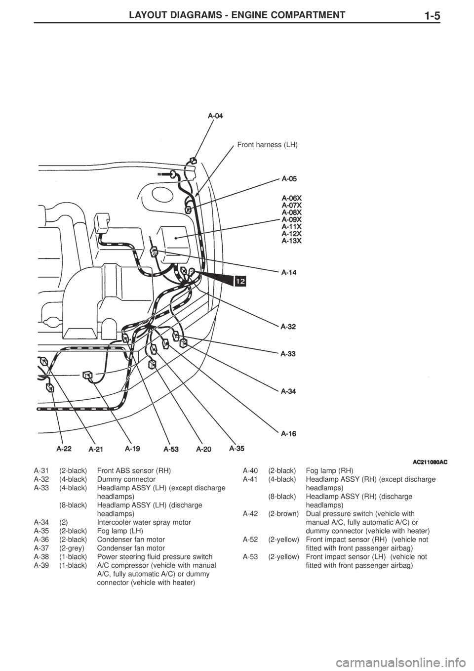
LAYOUT DIAGRAMS - ENGINE COMPARTMENT1-5
A-31 (2-black) Front ABS sensor (RH)
A-32 (4-black) Dummy connector
A-33 (4-black) Headlamp ASSY (LH) (except discharge
headlamps)
(8-black) Headlamp ASSY (LH) (discharge
headlamps)
A-34 (2) Intercooler water spray motor
A-35 (2-black) Fog lamp (LH)
A-36 (2-black) Condenser fan motor
A-37 (2-grey) Condenser fan motor
A-38 (1-black) Power steering fluid pressure switch
A-39 (1-black) A/C compressor (vehicle with manual
A/C, fully automatic A/C) or dummy
connector (vehicle with heater)A-40 (2-black) Fog lamp (RH)
A-41 (4-black) Headlamp ASSY (RH) (except discharge
headlamps)
(8-black) Headlamp ASSY (RH) (discharge
headlamps)
A-42 (2-brown) Dual pressure switch (vehicle with
manual A/C, fully automatic A/C) or
dummy connector (vehicle with heater)
A-52 (2-yellow) Front impact sensor (RH) (vehicle not
fitted with front passenger airbag)
A-53 (2-yellow) Front impact sensor (LH) (vehicle not
fitted with front passenger airbag)
Front harness (LH)
Page 156 of 364
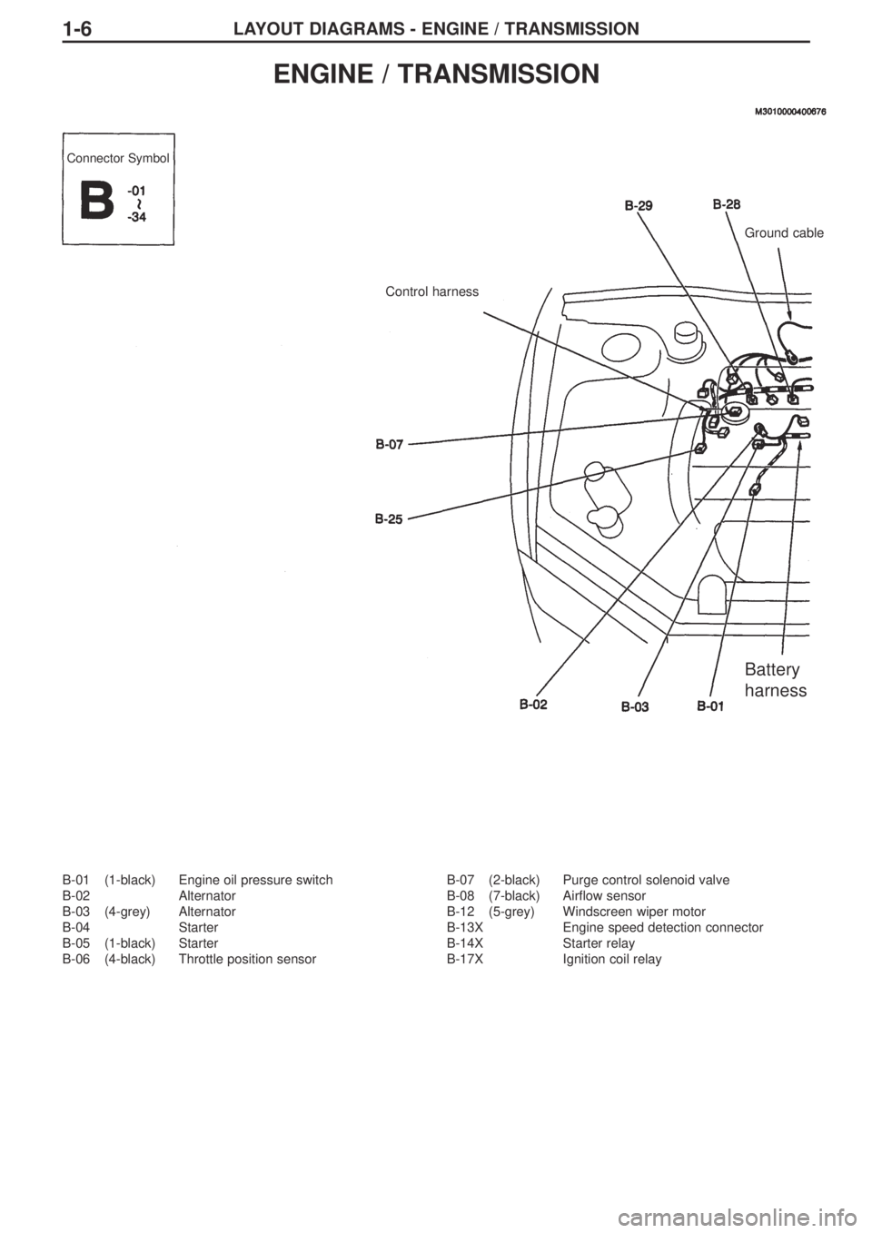
LAYOUT DIAGRAMS - ENGINE / TRANSMISSION1-6
B-01 (1-black) Engine oil pressure switch
B-02 Alternator
B-03 (4-grey) Alternator
B-04 Starter
B-05 (1-black) Starter
B-06 (4-black) Throttle position sensorB-07 (2-black) Purge control solenoid valve
B-08 (7-black) Airflow sensor
B-12 (5-grey) Windscreen wiper motor
B-13X Engine speed detection connector
B-14X Starter relay
B-17X Ignition coil relay
ENGINE / TRANSMISSION
Connector Symbol
Control harnessGround cable
Battery
harness
Page 157 of 364
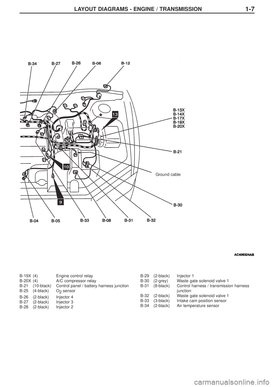
1-7
B-19X (4) Engine control relay
B-20X (4) A/C compressor relay
B-21 (10-black) Control panel / battery harness junction
B-25 (4-black) O
2sensor
B-26 (2-black) Injector 4
B-27 (2-black) Injector 3
B-28 (2-black) Injector 2B-29 (2-black) Injector 1
B-30 (2-grey) Waste gate solenoid valve 1
B-31 (8-black) Control harness / transmission harness
junction
B-32 (2-black) Waste gate solenoid valve 1
B-33 (3-black) Intake cam position sensor
B-34 (2-black) Air temperature sensor
LAYOUT DIAGRAMS - ENGINE / TRANSMISSION
Ground cable
Page 158 of 364
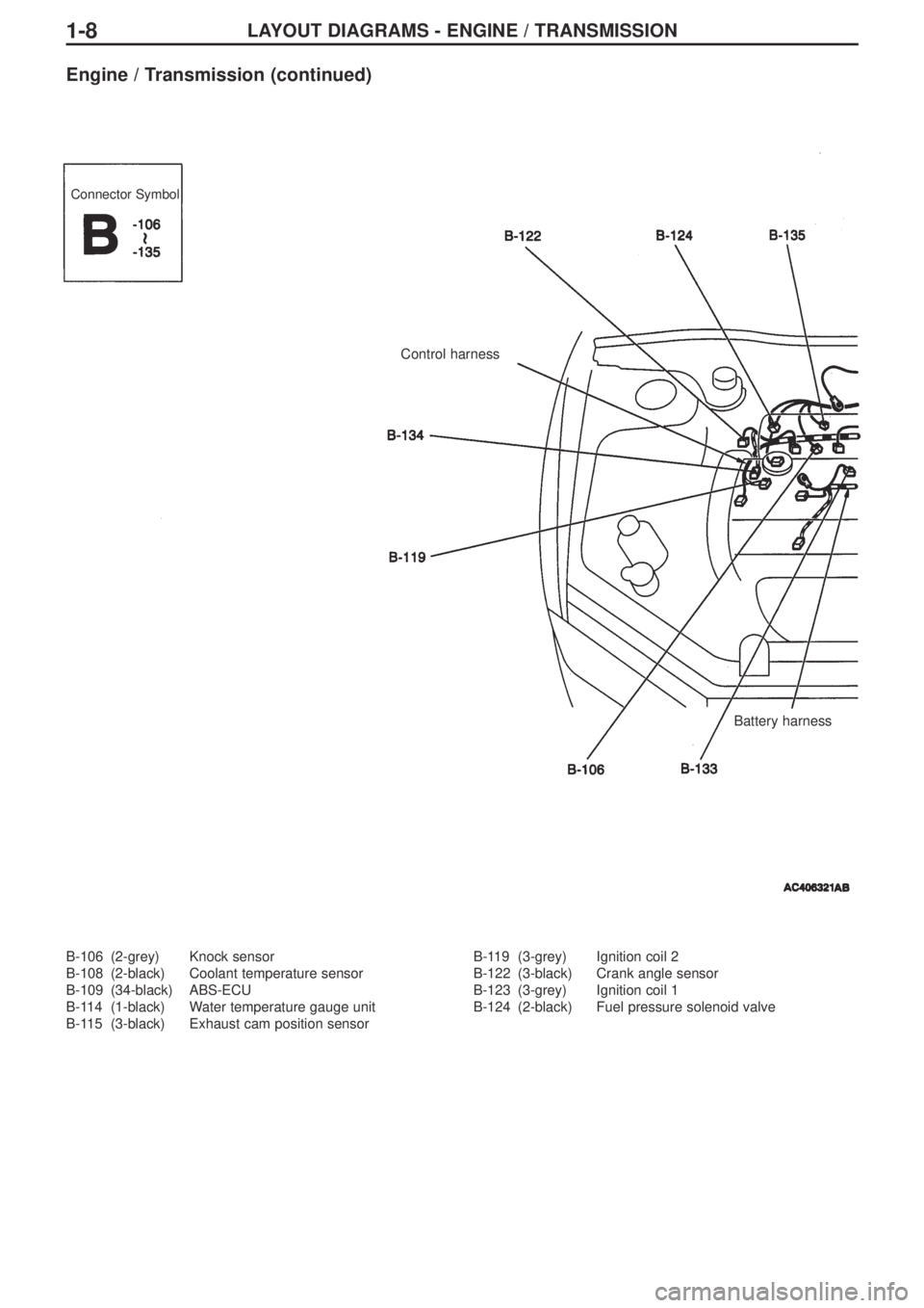
LAYOUT DIAGRAMS - ENGINE / TRANSMISSION1-8
B-106 (2-grey) Knock sensor
B-108 (2-black) Coolant temperature sensor
B-109 (34-black) ABS-ECU
B-114 (1-black) Water temperature gauge unit
B-115 (3-black) Exhaust cam position sensorB-119 (3-grey) Ignition coil 2
B-122 (3-black) Crank angle sensor
B-123 (3-grey) Ignition coil 1
B-124 (2-black) Fuel pressure solenoid valve
Engine / Transmission (continued)
Connector Symbol
Control harness
Battery harness
Page 159 of 364
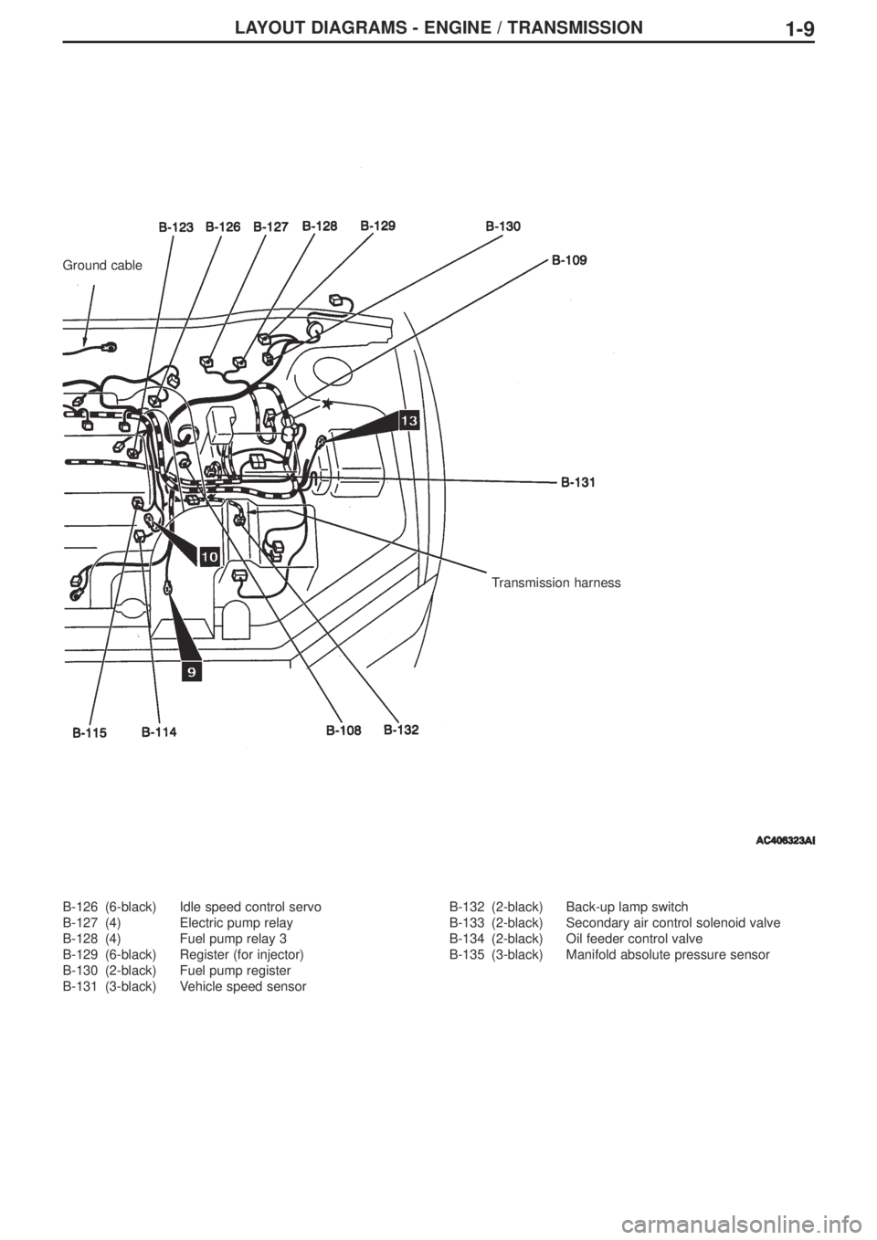
LAYOUT DIAGRAMS - ENGINE / TRANSMISSION1-9
B-126 (6-black) Idle speed control servo
B-127 (4) Electric pump relay
B-128 (4) Fuel pump relay 3
B-129 (6-black) Register (for injector)
B-130 (2-black) Fuel pump register
B-131 (3-black) Vehicle speed sensorB-132 (2-black) Back-up lamp switch
B-133 (2-black) Secondary air control solenoid valve
B-134 (2-black) Oil feeder control valve
B-135 (3-black) Manifold absolute pressure sensor
Ground cable
Transmission harness
Page 160 of 364
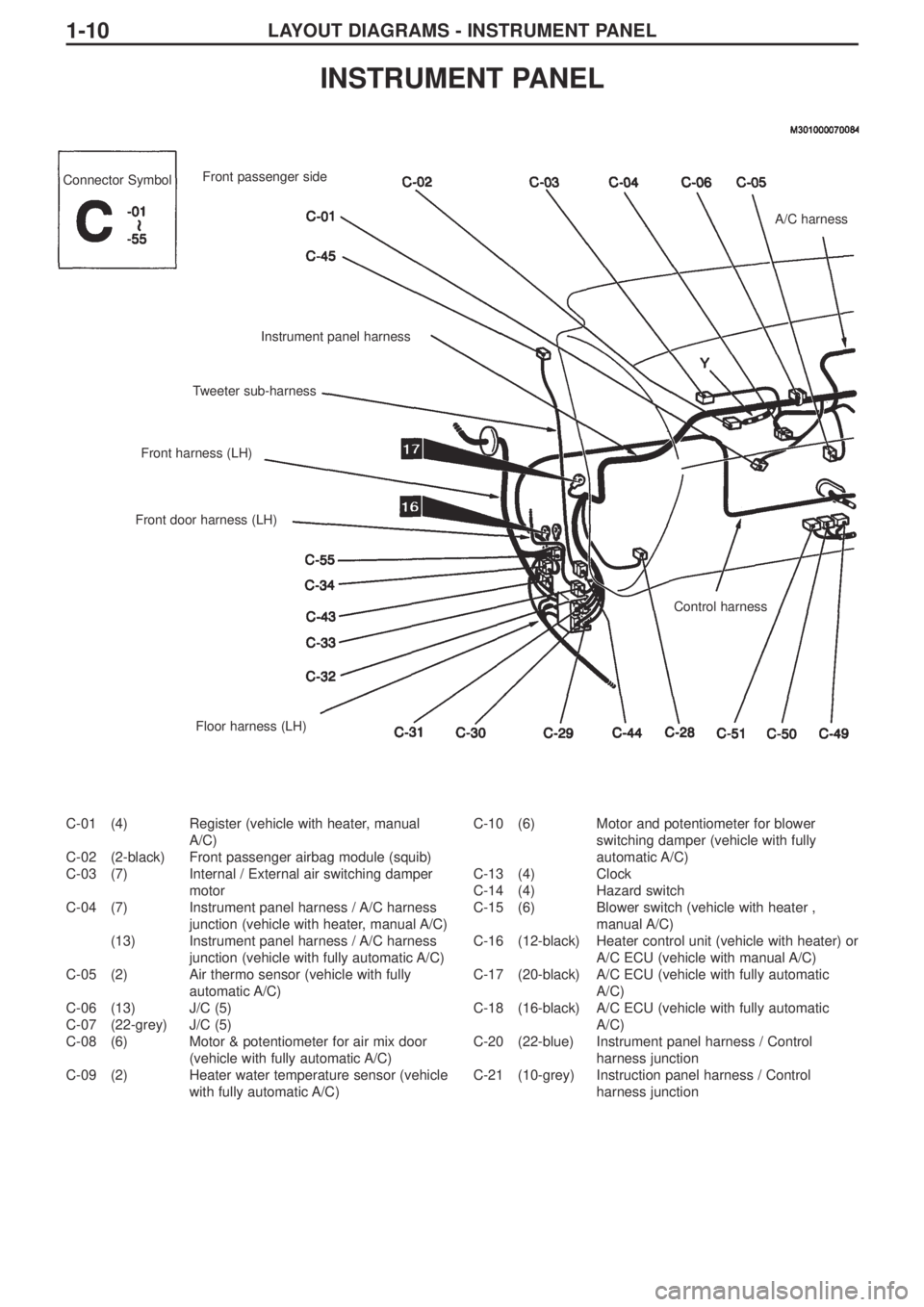
LAYOUT DIAGRAMS - INSTRUMENT PANEL1-10
C-01 (4) Register (vehicle with heater, manual
A/C)
C-02 (2-black) Front passenger airbag module (squib)
C-03 (7) Internal / External air switching damper
motor
C-04 (7) Instrument panel harness / A/C harness
junction (vehicle with heater, manual A/C)
(13) Instrument panel harness / A/C harness
junction (vehicle with fully automatic A/C)
C-05 (2) Air thermo sensor (vehicle with fully
automatic A/C)
C-06 (13) J/C (5)
C-07 (22-grey) J/C (5)
C-08 (6) Motor & potentiometer for air mix door
(vehicle with fully automatic A/C)
C-09 (2) Heater water temperature sensor (vehicle
with fully automatic A/C)C-10 (6) Motor and potentiometer for blower
switching damper (vehicle with fully
automatic A/C)
C-13 (4) Clock
C-14 (4) Hazard switch
C-15 (6) Blower switch (vehicle with heater ,
manual A/C)
C-16 (12-black) Heater control unit (vehicle with heater) or
A/C ECU (vehicle with manual A/C)
C-17 (20-black) A/C ECU (vehicle with fully automatic
A/C)
C-18 (16-black) A/C ECU (vehicle with fully automatic
A/C)
C-20 (22-blue) Instrument panel harness / Control
harness junction
C-21 (10-grey) Instruction panel harness / Control
harness junction
INSTRUMENT PANEL
Connector Symbol
A/C harness
Control harness
Floor harness (LH) Front door harness (LH)Front harness (LH)Tweeter sub-harnessInstrument panel harness Front passenger side
Trending: air conditioning, parking brake, fuel tank removal, check engine, check oil, bonnet, radiator
