air condition MITSUBISHI LANCER EVOLUTION IX 2005 Workshop Manual
[x] Cancel search | Manufacturer: MITSUBISHI, Model Year: 2005, Model line: LANCER EVOLUTION IX, Model: MITSUBISHI LANCER EVOLUTION IX 2005Pages: 364, PDF Size: 14.38 MB
Page 45 of 364
MPI – TROUBLESHOOTING
13A-5
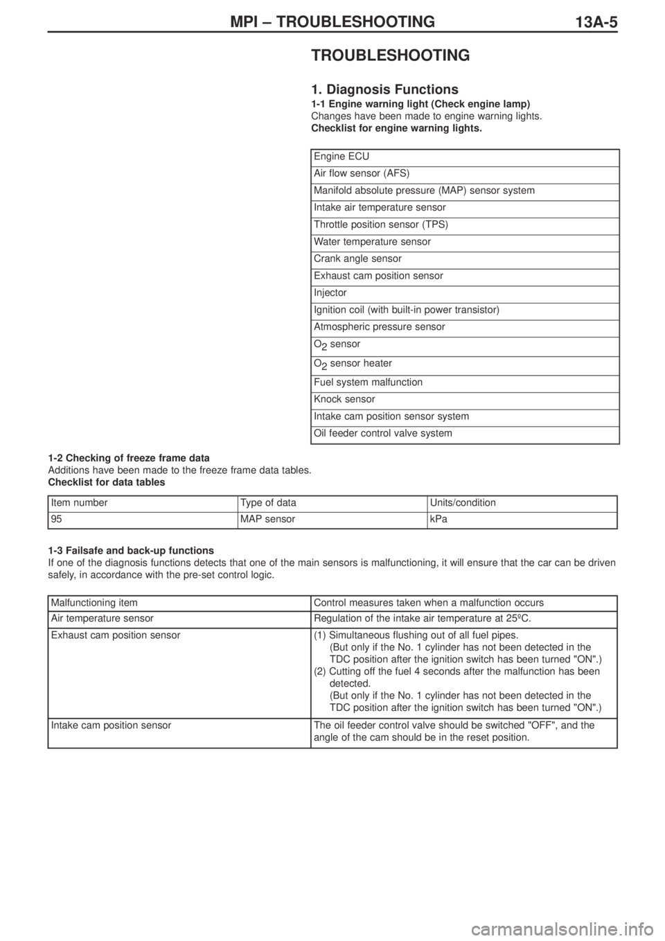
TROUBLESHOOTING
1. Diagnosis Functions
1-1 Engine warning light (Check engine lamp)
Changes have been made to engine warning lights.
Checklist for engine warning lights.
1-2 Checking of freeze frame data
Additions have been made to the freeze frame data tables.
Checklist for data tables
1-3 Failsafe and back-up functions
If one of the diagnosis functions detects that one of the main sensors is malfunctioning, it will ensure that the car can be driven
safely, in accordance with the pre-set control logic.
Engine ECU
Air flow sensor (AFS)
Manifold absolute pressure (MAP) sensor system
Intake air temperature sensor
Throttle position sensor (TPS)
Water temperature sensor
Crank angle sensor
Exhaust cam position sensor
Injector
Ignition coil (with built-in power transistor)
Atmospheric pressure sensor
O
2sensor
O
2sensor heater
Fuel system malfunction
Knock sensor
Intake cam position sensor system
Oil feeder control valve system
Item numberType of data Units/condition
95MAP sensorkPa
Malfunctioning itemControl measures taken when a malfunction occurs
Air temperature sensorRegulation of the intake air temperature at 25ºC.
Exhaust cam position sensor(1) Simultaneous flushing out of all fuel pipes.
(But only if the No. 1 cylinder has not been detected in the
TDC position after the ignition switch has been turned "ON".)
(2) Cutting off the fuel 4 seconds after the malfunction has been
detected.
(But only if the No. 1 cylinder has not been detected in the
TDC position after the ignition switch has been turned "ON".)
Intake cam position sensorThe oil feeder control valve should be switched "OFF", and the
angle of the cam should be in the reset position.
Page 47 of 364
13A-7MPI – TROUBLESHOOTING
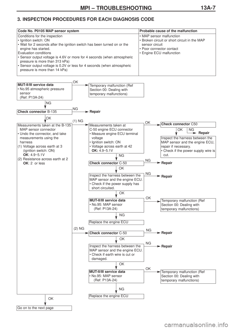
3. INSPECTION PROCEDURES FOR EACH DIAGNOSIS CODE
MUT-II/III service data
•No.95 atmospheric pressure
sensor
(Ref: P13A-24)
Go on to the next page
Measurements taken at
C-50 engine ECU connector
•Measure engine ECU terminal
voltage
•Ignition switch: ON
•Voltage across earth at 42
OK:4.9~5.1V
Check connectorC-50
Inspect the harness between the
MAP sensor and the engine ECU.
•Check if the power supply has
short circuited.
MUT-II/III service data
• No.95: MAP sensor
(Ref: P13A-24)
Replace the engine ECU
Check connectorC-50
Inspect the harness between the
MAP sensor and the engine ECU.
•Check if earth wire is cut or
damaged.
MUT-II/III service data
•No.95: MAP sensor
(Ref: P13A-24)
Replace the engine ECU
Check connectorC50
Inspect the harness between the
MAP sensor and the engine ECU,
repair if necessary.
•Check if the power supply wire is
cut.
Temporary malfunction (Ref
Section 00: Dealing with
temporary malfunctions)
Measurements taken at the B-135
MAP sensor connector
•Undo the connector, and take
measurements using the
harness
(1) Voltage across earth at 3
(ignition switch: ON)
OK: 4.9~5.1V
(2) Resistance across earth at 2
OK: 2Ω or less
Temporary malfunction (Ref
Section 00: Dealing with
temporary malfunctions)
Check connectorB-135
NG
(2) NG (1) NGOK
NG
OK
OK
Temporary malfunction (Ref
Section 00: Dealing with
temporary malfunctions)
NG
OK
NG
OK
OK
NGOK
NG
OK
NG
Repair
NG
OK
OK
NG
NG
OK
Repair
Repair
Repair
Repair
Repair
Code No. P0105 MAP sensor systemProbable cause of the malfunction
Conditions for the inspection
• Ignition switch: ON
• Wait for 2 seconds after the ignition switch has been turned on or the
engine has started.
Evaluation conditions
• Sensor output voltage is 4.6V or more for 4 seconds (when atmospheric
pressure is more than 313 kPa)
• Sensor output voltage is 0.2V or less for 4 seconds (when atmospheric
pressure is more than 14 kPa)• MAP sensor malfunction
• Broken circuit or short circuit in the MAP
sensor circuit
• Poor connector contact
• Engine ECU malfunction
Page 49 of 364
13A-9MPI – TROUBLESHOOTING
Check connector B-115
To next page
Check connectorB-19X
Measurements taken at engine
ECU connector C-50
•Measurement of voltage at
engine ECU terminals
•Undo the B-115 exhaust cam
position sensor connector
•Ignition switch: ON
•Voltage across earth at 50
OK: 4.9~5.1V
Inspect the harness between the
exhaust cam position sensor and
the engine control relay, repair if
necessary
•Check if the power supply wire
is cut or has short circuited
Inspect the harness between the
exhaust cam position sensor and
the engine ECU
•Check if the output wire has
short circuited
Check that the problem has been
solved
Check connectorC-50
Check connectorC-50
Inspect the harness between the
exhaust cam position sensor and
the engine ECU, repair if
necessary
•Check if the output wire is cut
Temporary malfunction (Ref
Section : Dealing with temporary
malfunctions)
Temporary malfunction (Ref
Section 00: Dealing with
temporary malfunctions)
Measurements taken at the B-115
connector of the exhaust cam
position sensor
•Undo the connector and take
measurements using the
harness
(1) Voltage across earth at 3
(ignition switch: ON)
OK:battery voltage
(2) Voltage across earth at 2
(ignition switch: ON)
OK:4.9~5.1V
(3) Resistance across earth at 1
OK:Less than 2Ω
NGRepair
Repair
OK
NG
OK
OK
NG
OK
NG
NG
OK
NGNG
NGOK
Inspect the harness between the
exhaust cam position sensor and
the engine ECU
•Check if the earth wire is cut or
damaged
Check connectorC-49
OK
OK
Replace engine ECU
NG
Check the problem has been
solved
Replace engine ECU
NG
OK
(1) NG
(2) NG
(3) NG
OK
OK
Repair
Repair
Repair
Repair
Repair
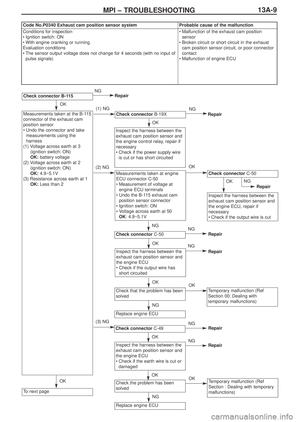
Code No.P0340 Exhaust cam position sensor systemProbable cause of the malfunction
Conditions for inspection
•Ignition switch: ON
•With engine cranking or running
Evaluation conditions
•The sensor output voltage does not change for 4 seconds (with no input of
pulse signals)•Malfunction of the exhaust cam position
sensor
•Broken circuit or short circuit in the exhaust
cam position sensor circuit, or poor connector
contact
•Malfunction of engine ECU
Page 51 of 364
13A-11MPI – TROUBLESHOOTING
Check connectorB-33
To next page
Check connectorsB-19X & C-23
Inspect the harness between the
intake cam position sensor and
the engine control relay, repair if
necessary
•Check if the power supply wire
is cut or has short circuited
Measurements taken at engine
ECU connector C-50
•Measurement of voltage at
engine ECU terminals
•Undo the B-33 intake cam
position sensor connector
•Ignition switch: ON
•Voltage across earth 53
OK:4.9~5.1V
Check connectorC-50
Check connectorC-49
Inspect the harness between the
intake cam position sensor and
the engine ECU
•Check if the earth wire is cut or
damaged
Harness inspection between the
intake cam position sensor and
the engine ECU
•Check if the earth wire is cut or
damaged
Replace the engine ECU
Replace engine ECU
Check that the problem has been
solved
Check that the problem has been
solved
Check connector C-50
Inspect the harness between the
intake cam position sensor and
the engine ECU, repair if
necessary
•Check if the output wire is cut
Temporary malfunction (Ref
Section 00: Dealing with
temporary malfunctions)
Temporary malfunction (Ref
Section 00: Dealing with
temporary malfunctions)
Measurements taken at the B-33
connector of the intake cam
position sensor
•Undo the connector and take
measurements using the
harness
(1) Voltage across earth at 3
(ignition switch: ON)
OK:battery voltage
(2) Voltage across earth at 2
(ignition switch: ON)
OK:4.9~5.1V
(3) Resistance across earth at 1
OK:Less than 2Ω
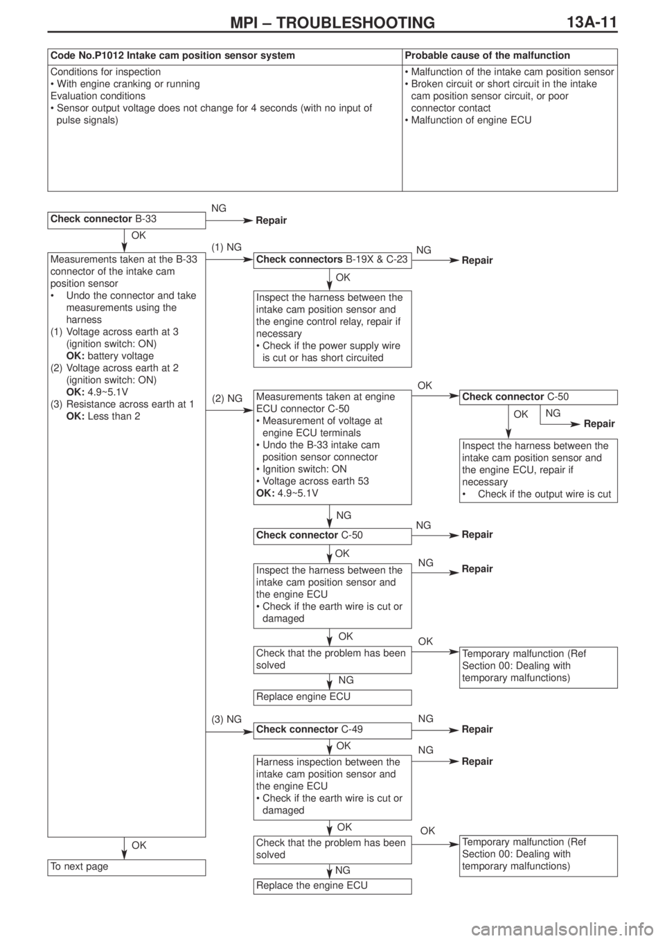
Code No.P1012 Intake cam position sensor systemProbable cause of the malfunction
Conditions for inspection
• With engine cranking or running
Evaluation conditions
• Sensor output voltage does not change for 4 seconds (with no input of
pulse signals)•Malfunction of the intake cam position sensor
•Broken circuit or short circuit in the intake
cam position sensor circuit, or poor
connector contact
•Malfunction of engine ECU
OK
OK
NG
(1) NG
(2) NG
(3) NG
OK
NG
NG
OK
OK
OK
NG
NG
NG
OK
NG
OK OK
NG
NG
OK
OKNG
Repair
Repair
Repair
Repair
Repair
Repair
Repair
Page 53 of 364
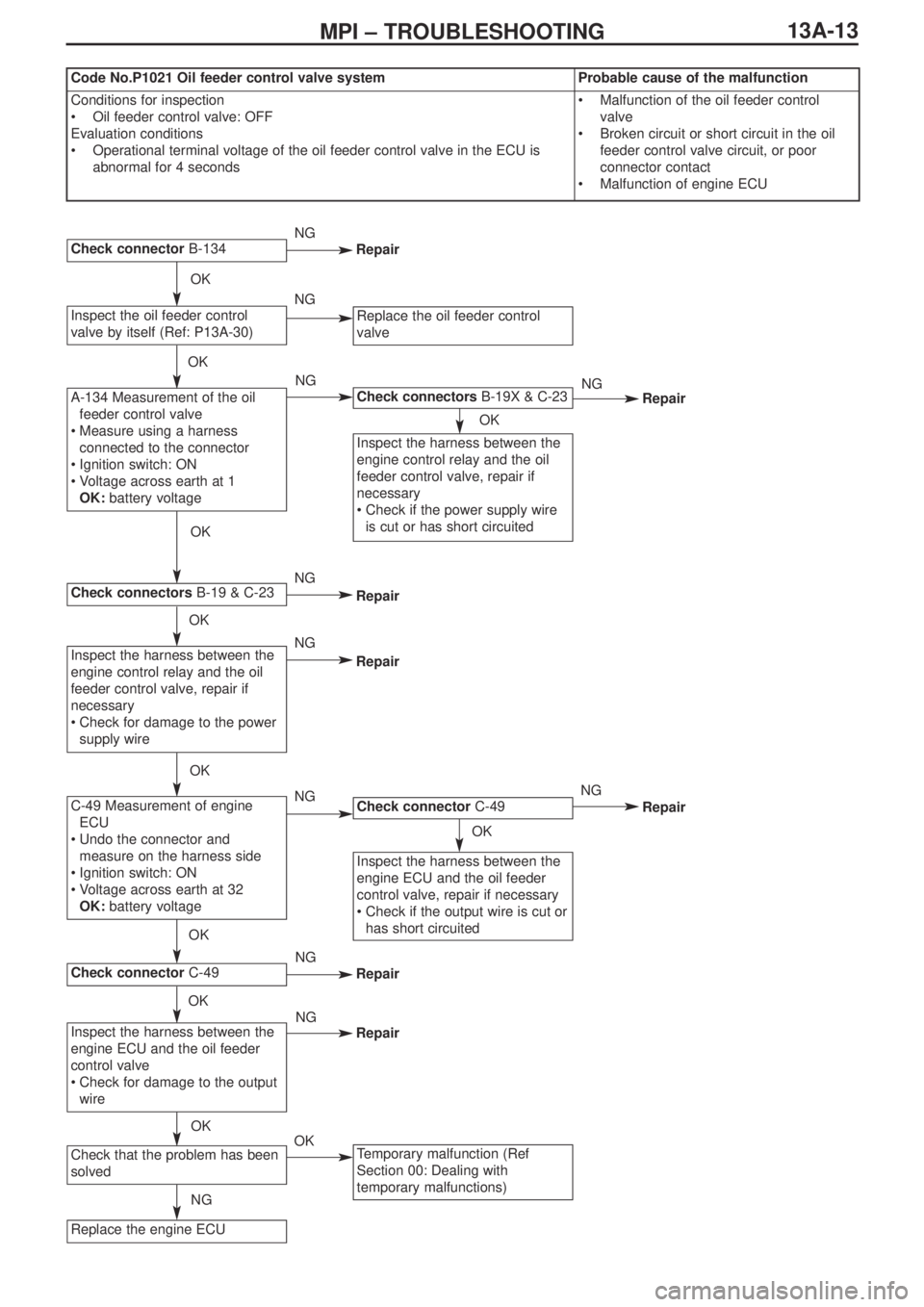
13A-13MPI – TROUBLESHOOTING
Replace the engine ECU
Check connectors B-19X & C-23
Check connector B-134
Check connectors B-19 & C-23
Check connector C-49
Check that the problem has been
solved
Inspect the oil feeder control
valve by itself (Ref: P13A-30)
Inspect the harness between the
engine control relay and the oil
feeder control valve, repair if
necessary
•Check for damage to the power
supply wire
Inspect the harness between the
engine control relay and the oil
feeder control valve, repair if
necessary
•Check if the power supply wire
is cut or has short circuited
Check connectorC-49
Inspect the harness between the
engine ECU and the oil feeder
control valve, repair if necessary
•Check if the output wire is cut or
has short circuited
Temporary malfunction (Ref
Section 00: Dealing with
temporary malfunctions)
Replace the oil feeder control
valve
A-134 Measurement of the oil
feeder control valve
•Measure using a harness
connected to the connector
•Ignition switch: ON
•Voltage across earth at 1
OK:battery voltage
C-49 Measurement of engine
ECU
•Undo the connector and
measure on the harness side
•Ignition switch: ON
•Voltage across earth at 32
OK:battery voltage
Inspect the harness between the
engine ECU and the oil feeder
control valve
•Check for damage to the output
wire
OK
NG
OKOK
OK
OK
OK
OK
OK
OK
NG
NG
NG
NG
NG
NG
NG
NG
NG
NG
OK
OK
Repair
Repair
Repair
Repair
Repair
Repair
Repair
Code No.P1021 Oil feeder control valve systemProbable cause of the malfunction
Conditions for inspection
•Oil feeder control valve: OFF
Evaluation conditions
•Operational terminal voltage of the oil feeder control valve in the ECU is
abnormal for 4 seconds•Malfunction of the oil feeder control
valve
•Broken circuit or short circuit in the oil
feeder control valve circuit, or poor
connector contact
•Malfunction of engine ECU
Page 54 of 364
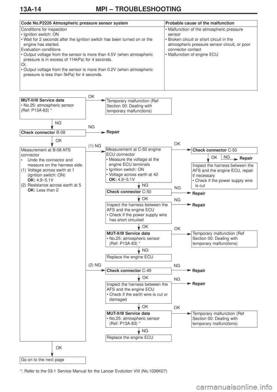
13A-14MPI – TROUBLESHOOTING
MUT-II/III Service data
•No.25: atmospheric sensor
(Ref: P13A-83) *Temporary malfunction (Ref
Section 00: Dealing with
temporary malfunctions)
Check connectorC-50
Check connectorC-50
Check connector C-49
Check connectorB-08
Go on to the next page
Inspect the harness between the
AFS and the engine ECU
•Check if the power supply wire
has short circuited
Temporary malfunction (Ref
Section 00: Dealing with
temporary malfunctions)
Temporary malfunction (Ref
Section 00: Dealing with
temporary malfunctions)
Inspect the harness between the
AFS and the engine ECU, repair
if necessary
•Check if the power supply wire
is cut
MUT-II/III Service data
•No.25: atmospheric sensor
(Ref: P13A-83) *
Inspect the harness between the
AFS and the engine ECU
•Check if the earth wire is cut or
damaged
MUT-II/III Service data
•No.25: atmospheric sensor
(Ref: P13A-83) *
Replace the engine ECU
Replace the engine ECU
Measurement at B-08 AFS
connector
•Undo the connector and
measure on the harness side.
(1) Voltage across earth at 1
(ignition switch: ON)
OK:4.9~5.1V
(2) Resistance across earth at 5
OK:Less than 2ΩMeasurement at C-50 engine
ECU connector
•Measure the voltage at the
engine ECU terminals
•Ignition switch: ON
•Voltage across earth at 42
OK:4.9~5.1V
*: Refer to the 03-1 Service Manual for the Lancer Evolution VIII (No.1036K07)
Code No.P2226 Atmospheric pressure sensor systemProbable cause of the malfunction
Conditions for inspection
•Ignition switch: ON
•Wait for 2 seconds after the ignition switch has been turned on or the
engine has started.
Evaluation conditions
•Output voltage from the sensor is more than 4.5V (when atmospheric
pressure is in excess of 114kPa) for 4 seconds.
Or,
•Output voltage from the sensor is more than 0.2V (when atmospheric
pressure is less than 5kPa) for 4 seconds.•Malfunction of the atmospheric pressure
sensor
•Broken circuit or short circuit in the
atmospheric pressure sensor circuit, or poor
connector contact
•Malfunction of engine ECU
NG
OK
OK
NG
(1) NG
(2) NG
OK
Repair
Repair
Repair
Repair
OK
NG
OK
OK
NG
OK
OK
NG
OK
OK
NG
NG
NG
NG
OKNGRepair
Repair
Page 70 of 364
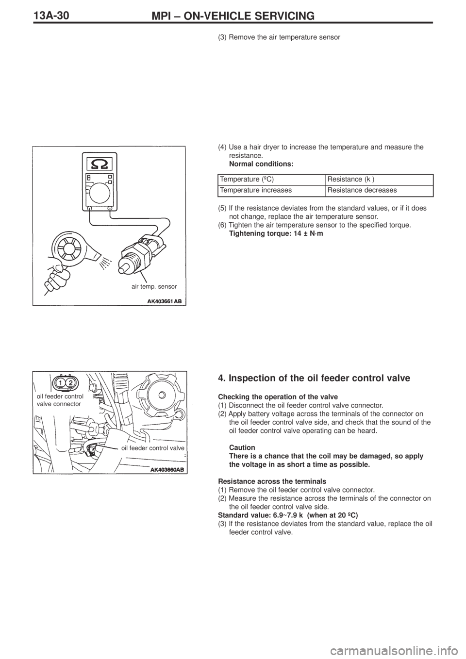
MPI – ON-VEHICLE SERVICING13A-30
(3) Remove the air temperature sensor
(4) Use a hair dryer to increase the temperature and measure the
resistance.
Normal conditions:
air temp. sensor
Temperature (ºC)Resistance (kΩ)
Temperature increasesResistance decreases
(5) If the resistance deviates from the standard values, or if it does
not change, replace the air temperature sensor.
(6) Tighten the air temperature sensor to the specified torque.
Tightening torque: 14 ± N·m
4. Inspection of the oil feeder control valve
Checking the operation of the valve
(1) Disconnect the oil feeder control valve connector.
(2) Apply battery voltage across the terminals of the connector on
the oil feeder control valve side, and check that the sound of the
oil feeder control valve operating can be heard.
Caution
There is a chance that the coil may be damaged, so apply
the voltage in as short a time as possible.
Resistance across the terminals
(1) Remove the oil feeder control valve connector.
(2) Measure the resistance across the terminals of the connector on
the oil feeder control valve side.
Standard value: 6.9~7.9 kΩ (when at 20 ºC)
(3) If the resistance deviates from the standard value, replace the oil
feeder control valve.oil feeder control
valve connector
oil feeder control valve
Page 188 of 364
3-1
SECTION 3
CIRCUIT DIAGRAMS
CONTENTS
J/B ............................................................3-4
J/C ............................................................3-6
Central Junction....................................3-11
Power Supply ........................................3-18
Starting System ....................................3-23
Ignition ...................................................3-24
Charging ................................................3-26
Engine Control ......................................3-28
Cooling ..................................................3-36
Lighting
Headlights (excl. discharge type).....................3-38
Headlights (discharge type) .............................3-42
Tail lights, position lights, licence plate
lights, lighting monitor report buzzer................3-46
Cabin lights, boot compartment lights,
ignition key cylinder illumination light,
door ajar indicator light ....................................3-50
Fog lamps ........................................................3-54
Headlight levelling system ...............................3-58
Signals
Turn signal lights, hazard warning lights .........3-60
Reversing lights ...............................................3-64
Stop lights ........................................................3-65
Horn .................................................................3-66
Meters
Needle meters..................................................3-68
Remaining fuel warning light, oil pressure
warning light, brake warning light,
seatbelt warning light .......................................3-70
Door Opening / Closing Control
Power windows ................................................3-72
Central door locking
(vehicle without keyless entry) .........................3-78
Central door locking
(vehicle with keyless entry) ..............................3-80
Temperature Control
Heater ..............................................................3-86
Manual air-conditioning ....................................3-90
Fully automatic air-conditioning .......................3-96
Vision / Safety
Windscreen washer / wipers ..........................3-104
Rear washer / wiper .......................................3-108
Demister
(vehicle with heater or manual A/C) ...............3-110
Demister, door mirror heating elements
(vehicle with full auto A/C)..............................3-112
Electric stowable remote control
door mirrors ....................................................3-114
Accessories
Spare audio connectors .................................3-118
Clock ..............................................................3-120
Cigarette lighter, ashtray illumination lamp ....3-121
Cont. on next page
Page 277 of 364
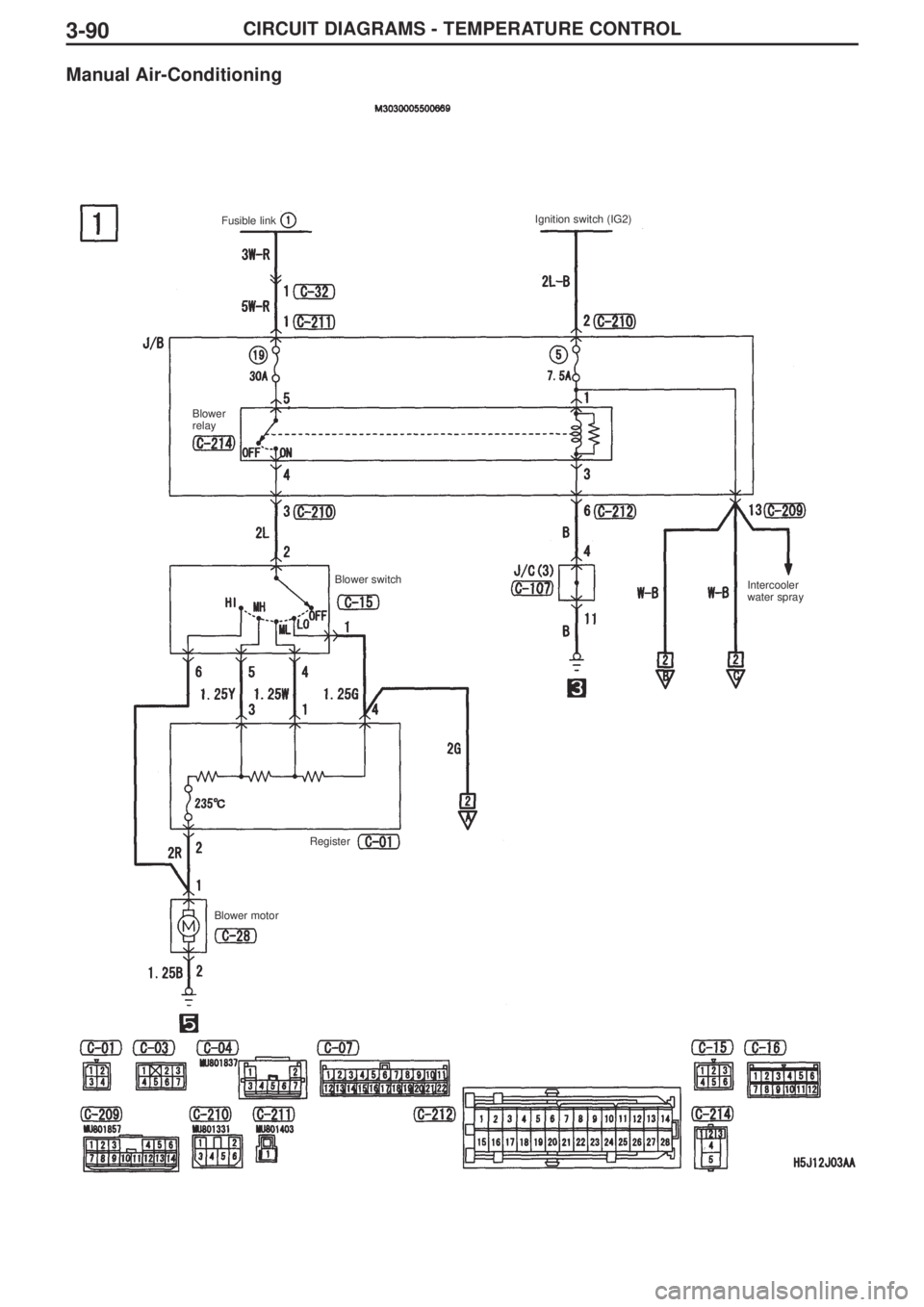
3-90CIRCUIT DIAGRAMS - TEMPERATURE CONTROL
Manual Air-Conditioning
Fusible link Ignition switch (IG2)
Blower
relay
Blower switch
Intercooler
water spray
Blower motorRegister
Page 279 of 364
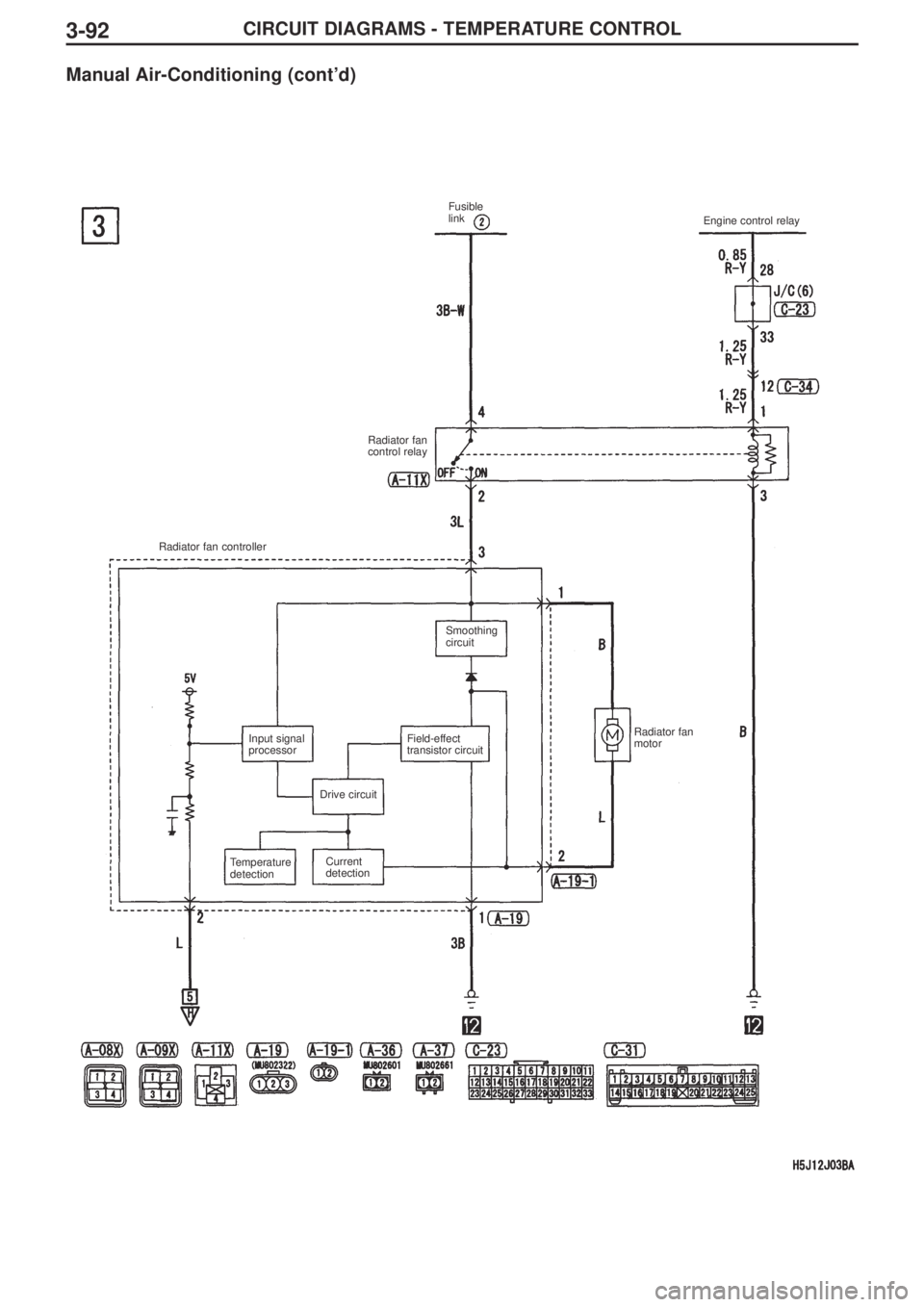
3-92CIRCUIT DIAGRAMS - TEMPERATURE CONTROL
Manual Air-Conditioning (cont’d)
Fusible
link
Engine control relay
Radiator fan
control relay
Radiator fan controller
Smoothing
circuit
Input signal
processorField-effect
transistor circuit
Drive circuit
Temperature
detectionCurrent
detectionRadiator fan
motor