fuel consumption MITSUBISHI LANCER EVOLUTION X 2008 Workshop Manual
[x] Cancel search | Manufacturer: MITSUBISHI, Model Year: 2008, Model line: LANCER EVOLUTION X, Model: MITSUBISHI LANCER EVOLUTION X 2008Pages: 241, PDF Size: 8.26 MB
Page 39 of 241

A/C-ECU
HEATER, AIR CONDITIONING AND VENTILATION55-7
A/C-ECUM2551001200265
CONTROL
.
FORCED DEF CONTROL
When air outlet position is switched to DEF, A/C is
automatically turned ON, and outside/inside air
selection damper is set to the fresh air position to
quickly defrost the windshield screen.
.
MAX A/C CONTROL
When the temperature adjustment knob is turned to
the maximum A/C position with the blower knob at
position other than OFF, the following controls are
made by the A/C-ECU.
NOTE: "*" Manual operation is disabled during max
A/C control.
.
MAX COOL, MAX HOT CONTROL
When the set temperature is at 18.0 °C <61°F>
(MAX COOL) or at 32.0
°C <89°F> (MAX HOT) with
the air outlet and air volume at the AUTO positions,
the following controls are made automatically by the
A/C-ECU.
NOTE: "*" indicates that when the automatic control
is not cancelled using the customise function, the
manual operation is disabled.
.
REAR WINDOW DEFOGGER TIMER
CONTROL
In order to prevent battery consumption, the defog-
ger is automatically turned OFF, 20 minutes after it is
turned ON.
.
IDLE-UP CONTROL
A/C-ECU and the engine ECU communicate with
each other through the CAN communication. The
idle-up speed of the engine is controlled in two steps
depending on the A/C load to secure the air cooling
performance during summer and to enhance fuel
economy in seasons with moderate temperature.
.
DETECTION CONTROL FOR
REFRIGERANT LEAKS
A/C-ECU determines if the refrigerant amount is less
than specified or refrigerant pressure is abnormal by
using the ambient temperature (ambient temperature
sensor to measure refrigerant inflation rate) and
refrigerant pressure (measured by the A/C pressure
sensor). When refrigerant amount or refrigerant pres
-
sure is judged abnormal, the compressor is cut-off to
protect the A/C system.
NOTE: When abnormality occurs, the A/C indicator
flashes.
.
PROTECTION CONTROL AT AIR BAG
DEPLOYMENT (DURING COLLISION)
When the air bag deployment is detected, the A/C
system is stopped.
.
CUSTOMISE FUNCTION
Depending on the user's preference, the following
functions can be selected. The programmed informa
-
tion is held even when the battery is disconnected.
•Automatic control for inside/outside air selection
Press and hold (approximately for 10 seconds)
the inside/outside air selection switch to cancel
the automatic control for inside/outside air selec
-
tion.
•A/C automatic control
Press and hold (approximately for 10 seconds)
the A/C switch to cancel the A/C automatic con
-
trol.
Subject to controlMAX COOL
Air mix damperMAX COOL position
Air outlet modeSelected position
Air volumeSelected position
Outside/inside air
selection damperAir recirculation position*
Air conditioner switchON*
Subject to
controlMAX COOLMAX HOT
Air mix
damperMAX COOL
positionMAX HOT
position
Air outlet
modeFACE positionFOOT position
Air volumeMaximumMaximum
Outside/insid
e air
selection
damperAir recirculation
position*Fresh air
position*
Air
conditioner
switchON*OFF*
Page 75 of 241

EMISSION CONTROL
ENGINE AND EMISSION CONTROL17-13
EXHAUST GAS RECIRCULATION (EGR) VALVE
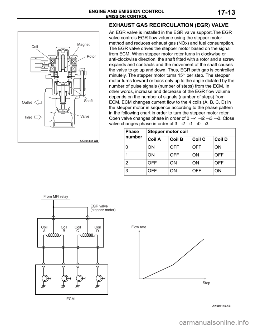
An EGR valve is installed in the EGR valve support.The EGR
valve controls EGR flow volume using the stepper motor
method and reduces exhaust gas (NOx) and fuel consumption.
The EGR valve drives the stepper motor based on the signal
from ECM. When stepper motor rotor turns in clockwise or
anti-clockwise direction, the shaft fitted with a rotor and a screw
expands and contracts and the movement of the shaft causes
the valve to go up and down. Thus, EGR path gap is controlled
minutely. The stepper motor turns 15
° per step. The stepper
motor turns forward or back only up to the angle dictated by the
number of pulse signals (number of steps) from the ECM. In
other words, increase and decrease of the EGR flow volume
depends on the number of signals (number of steps) from
ECM. ECM changes current flow to the 4 coils (A, B, C, D) in
the stepper motor in sequence according to the phase pattern
in the following chart in order to turn the stepper motor rotor.
Open valve changes phase in order of 0
→ 1 → 2 → 3 → 0. Close
valve changes phase in order of 3
→ 2 → 1 → 0 → 3.
Phase
numberStepper motor coil
Coil ACoil BCoil CCoil D
0ONOFFOFFON
1ONOFFONOFF
2OFFONONOFF
3OFFONOFFON
AK604144
Coil
Shaft
Valve Outlet
Inlet
Rotor
Magnet
AB
AK604145
From MFI relay
EGR valve
(stepper motor)
ECM Coil
ACoil
BCoil
CCoil
DFlow rate
Step
AB
Page 135 of 241

MIVEC (Mitsubishi Innovative Valve Timing Electronic Control System)
MULTIPORT FUEL SYSTEM (MFI)13A-42
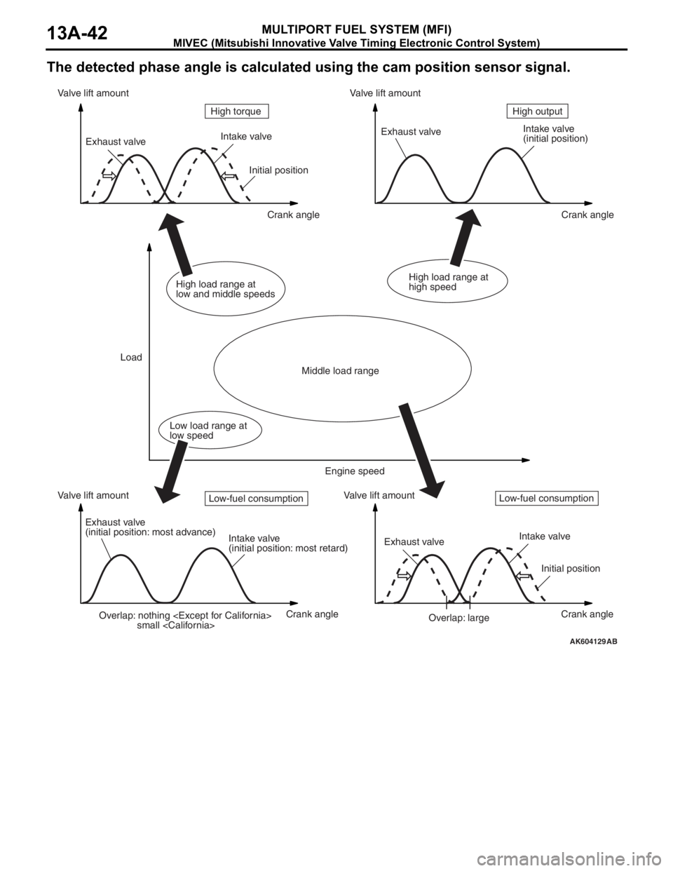
The detected phase angle is calculated using the cam position sensor signal.
AK604129AB
Overlap: nothing
small
(initial position)
Exhaust valve
(initial position: most advance)
Intake valve
(initial position: most retard)Exhaust valveIntake valve
Initial position
Overlap: large Initial position
Crank angle Crank angle
Crank angle Crank angle Valve lift amount Valve lift amountValve lift amount Valve lift amount
LoadHigh output High torque
Middle load range
Low load range at
low speedHigh load range at
low and middle speedsHigh load range at
high speed
Engine speed
Low-fuel consumptionLow-fuel consumption