MITSUBISHI LANCER EVOLUTION X 2008 Workshop Manual
Manufacturer: MITSUBISHI, Model Year: 2008, Model line: LANCER EVOLUTION X, Model: MITSUBISHI LANCER EVOLUTION X 2008Pages: 241, PDF Size: 8.26 MB
Page 231 of 241

GENERAL INFORMATION
WHEEL AND TIRE31-2
GENERAL INFORMATIONM2310000100941
•The wheels and tires of the following specifica-
tions have been established.
•Adopt the Tire Pressure Monitoring System
(TPMS).
•Warns driver of low tire pressure by illuminat-
ing the TPMS warning light on the combina-
tion meter.
•Warns driver of TPMS probrems by flashing*
the TPMS warning light on the combination
meter.
NOTE: *: Change to continuous illumination
after flashing for about 1 minute.
SPECIFICATIONS
.
ROAD WHEEL AND TIRE
SPARE WHEEL AND TIRE
NOTE: .
•The * mark indicates optional item.
•PCD indicates the pitch circle diameter of the wheel installation holes.
TIRE PRESSURE MONITORING SYSTEM (TPMS)M2310000200067
Refer to GROUP 42B − Keyless Operation System
(KOS)
P.42B-20 or GROUP 42C − Wireless Control
Module (WCM) P.42C-9.
ItemDEESGT S
TPMS warning
pressure kPa
(psi)Warning ON174 (25.2) or less174 (25.2) or less174 (25.2) or less
Warning OFF189 (27.4) or less189 (27.4) or less189 (27.4) or less
WheelTy p eSteel type or
Aluminium type
*
Aluminum typeAluminum type
Size16 × 6 1/2JJ16 × 6 1/2JJ18 × 7JJ
Amount of wheel
offset mm (in)46 (1.8)46 (1.8)46 (1.8)
PCD mm (in)114.3 (4.50)114.3 (4.50)114.3 (4.50)
TireSizeP205/60R16 91HP205/60R16 91HP215/45R18 89V
ItemSpecification
WheelTy p eSteel type
Size16 × 4T
Amount of wheel offset mm (in)40 (1.6)
PCD mm (in)114.3 (4.50)
TireSizeT125/70D16 96M
Page 232 of 241

27-1
GROUP 27
REAR AXLE
CONTENTS
GENERAL INFORMATION . . . . . . . .27-2
Page 233 of 241
GENERAL INFORMATION
REAR AXLE27-2
GENERAL INFORMATIONM2270000100478
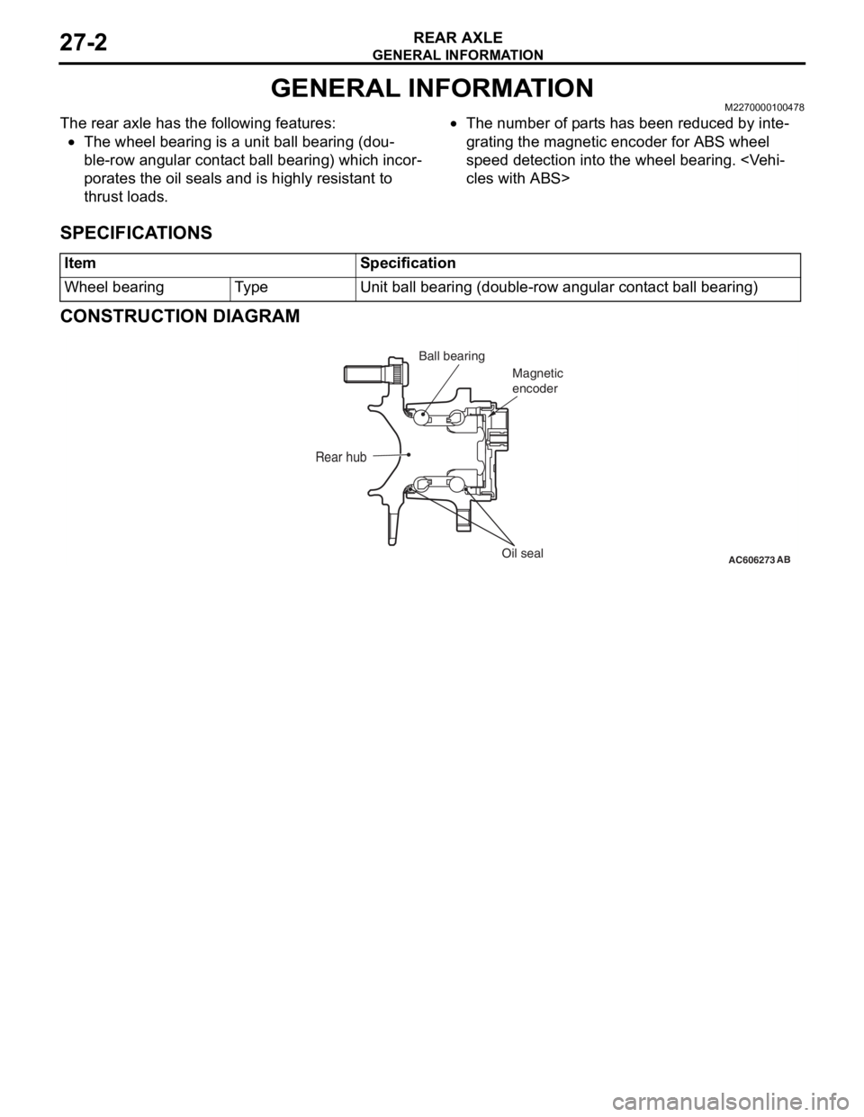
The rear axle has the following features:
•The wheel bearing is a unit ball bearing (dou-
ble-row angular contact ball bearing) which incor-
porates the oil seals and is highly resistant to
thrust loads.
•The number of parts has been reduced by inte-
grating the magnetic encoder for ABS wheel
speed detection into the wheel bearing.
cles with ABS>
SPECIFICATIONS
CONSTRUCTION DIAGRAM
ItemSpecification
Wheel bearingTy p eUnit ball bearing (double-row angular contact ball bearing)
AC606273
Rear hub
Oil seal Ball bearing
Magnetic
encoderAB
Page 234 of 241
37-1
GROUP 37
POWER STEERING
CONTENTS
GENERAL INFORMATION . . . . . . . .37-2
STEERING WHEEL . . . . . . . . . . . . . .37-3
STEERING SHAFT AND COLUMN . .37-4
OIL PUMP . . . . . . . . . . . . . . . . . . . . . .37-6
STEERING GEAR . . . . . . . . . . . . . . . .37-7
OIL RESERVOIR . . . . . . . . . . . . . . . .37-8
Page 235 of 241

GENERAL INFORMATION
POWER STEERING37-2
GENERAL INFORMATIONM2370000101003
FEATURES
A hydraulic power steering system has been adopted
to all models.
This steering system offers the following features:
•The support method of the steering gear to the
crossmember is realised by the left and right
internal bushings with inner cylinders. This sup
-
port method achieves higher rigidity of the steer-
ing gear and improves the steering feeling.
•Configuring the optimum flow characteristics and
gear valve feature improves the handling stability.
•Appropriate application of friction to the steering
gear cuts off the disturbance from the road sur
-
face and improves the stability during the
straight-ahead driving.
•Optimisation of the flexible tube in the high pres-
sure hose reduces the pump noise.
SPECIFICATIONS
ItemsSpecifications
Steering wheelTy p eThree-spoke type
Outside diameter mm (in)375 (14.7)
Maximum number of turns3.16
Steering columnColumn mechanismShock absorbing
mechanism and Tilt steering
mechanism
Power steering typeIntegral type (Engine
speed-dependent type)
Oil pumpTy p eVane type with fluid flow
amount control system
Basic discharge amount cm3/rev. (cu in/rev)8.1 (0.49)
Relief pressure MPa (psi)8.8 (1,276)
Reservoir typeSeparate type (Resin made)
Steering gearTy p eRack and pinion type
Stroke ratio (Rack stroke/Steering wheel
Maximum turning radius) mm/rev (in/rev)45.58 mm/rev (1.79 in/rev)
Rack stroke mm (in)144
Steering angleInner wheel40°50’
Outer wheel33°50’
Power steering fluidSpecified lubricantsGENUINE MITSUBISHI
POWER STEERING FLUID
Quantity dm3 (qt)Approximately 1.0 (1.06)
Page 236 of 241
STEERING WHEEL
POWER STEERING37-3
CONSTRUCTION DIAGRAM
STEERING WHEELM2370001000761
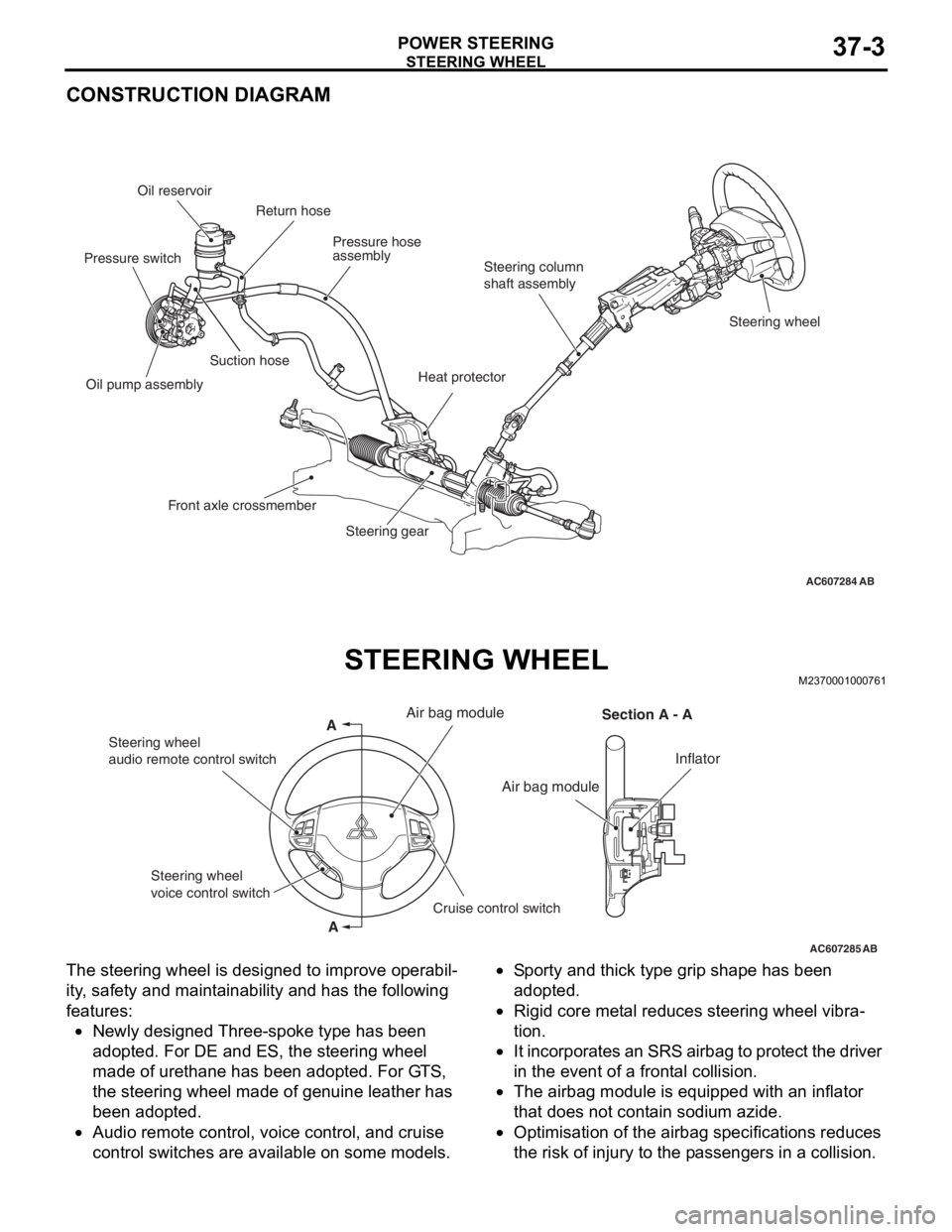
The steering wheel is designed to improve operabil-
ity, safety and maintainability and has the following
features:
•Newly designed Three-spoke type has been
adopted. For DE and ES, the steering wheel
made of urethane has been adopted. For GTS,
the steering wheel made of genuine leather has
been adopted.
•Audio remote control, voice control, and cruise
control switches are available on some models.
•Sporty and thick type grip shape has been
adopted.
•Rigid core metal reduces steering wheel vibra-
tion.
•It incorporates an SRS airbag to protect the driver
in the event of a frontal collision.
•The airbag module is equipped with an inflator
that does not contain sodium azide.
•Optimisation of the airbag specifications reduces
the risk of injury to the passengers in a collision.
AC607284AB
Steering wheel Steering column
shaft assembly Pressure hose
assembly Oil reservoir
Suction hose
Oil pump assembly
Steering gear Return hose
Front axle crossmember
Heat protector
Pressure switch
AC607285
A
AAir bag module
Section A - A
Inflator
Steering wheel
audio remote control switch
Cruise control switch Steering wheel
voice control switch
Air bag module
AB
Page 237 of 241
STEERING SHAFT AND COLUMN
POWER STEERING37-4
STEERING SHAFT AND COLUMNM2370002000667
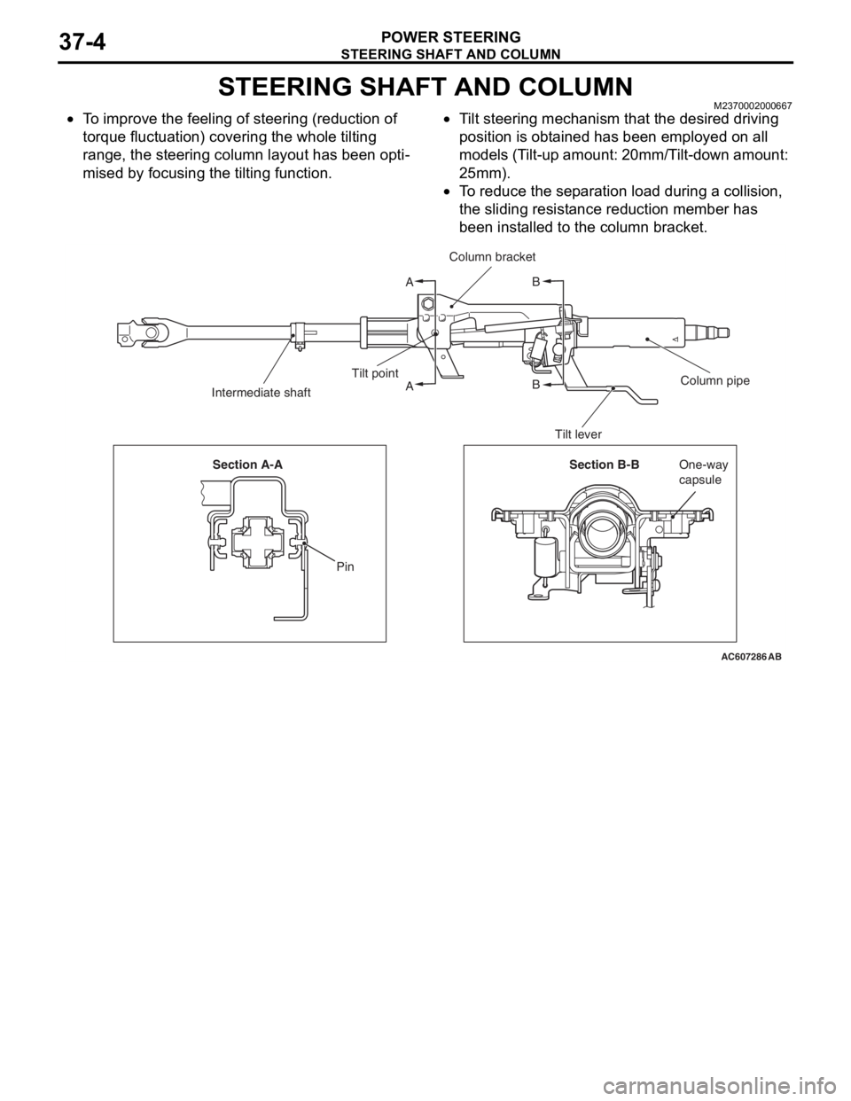
•To improve the feeling of steering (reduction of
torque fluctuation) covering the whole tilting
range, the steering column layout has been opti
-
mised by focusing the tilting function.
•Tilt steering mechanism that the desired driving
position is obtained has been employed on all
models (Tilt-up amount: 20mm/Tilt-down amount:
25mm).
•To reduce the separation load during a collision,
the sliding resistance reduction member has
been installed to the column bracket.
AC607286
A
AB
B
AB
Column bracket
Column pipe Tilt point
Intermediate shaft
Tilt lever
Section B-BOne-way
capsule Section A-A
Pin
Page 238 of 241
STEERING SHAFT AND COLUMN
POWER STEERING37-5
IMPACT-ABSORBING MECHANISM
.
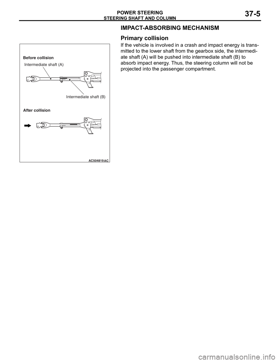
Primary collision
If the vehicle is involved in a crash and impact energy is trans-
mitted to the lower shaft from the gearbox side, the intermedi-
ate shaft (A) will be pushed into intermediate shaft (B) to
absorb impact energy. Thus, the steering column will not be
projected into the passenger compartment.
.
AC504819AC
Before collision
After collisionIntermediate shaft (A)
Intermediate shaft (B)
Page 239 of 241
OIL PUMP
POWER STEERING37-6
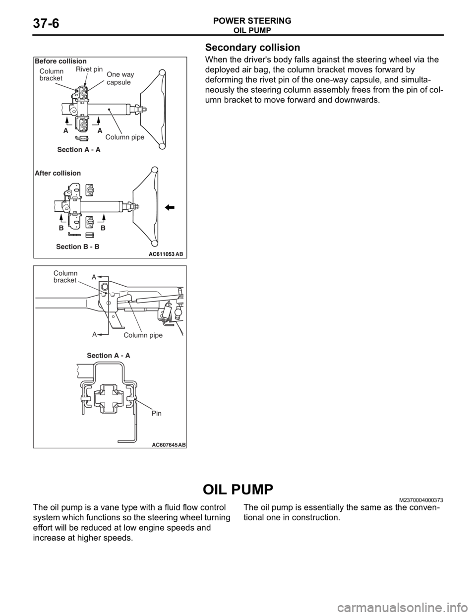
Secondary collision
When the driver's body falls against the steering wheel via the
deployed air bag, the column bracket moves forward by
deforming the rivet pin of the one-way capsule, and simulta
-
neously the steering column assembly frees from the pin of col-
umn bracket to move forward and downwards.
OIL PUMPM2370004000373
The oil pump is a vane type with a fluid flow control
system which functions so the steering wheel turning
effort will be reduced at low engine speeds and
increase at higher speeds. The oil pump is essentially the same as the conven-
tional one in construction.
AC611053AB
AA
BB
One way
capsule
Section B - BSection A - A Column
bracketRivet pin
Column pipe Before collision
After collision
AC607645AB
A
AColumn
bracket
Column pipe
Pin Section A - A
Page 240 of 241
STEERING GEAR
POWER STEERING37-7
STEERING GEARM2370003000499
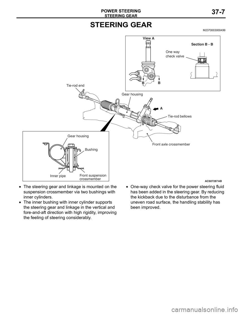
•The steering gear and linkage is mounted on the
suspension crossmember via two bushings with
inner cylinders.
•The inner bushing with inner cylinder supports
the steering gear and linkage in the vertical and
fore-and-aft direction with high rigidity, improving
the feeling of steering considerably.
•One-way check valve for the power steering fluid
has been added in the steering gear. By reducing
the kickback due to the disturbance from the
uneven road surface, the handling stability has
been improved.
AC607287AB
Tie-rod end
Gear housing
Gear housingTie-rod bellows
Front axle crossmember
Inner pipeBushing
Front suspension
crossmemberB
BView A
ASection B - B
One way
check valve