warning MITSUBISHI LANCER EVOLUTION X 2008 Workshop Manual
[x] Cancel search | Manufacturer: MITSUBISHI, Model Year: 2008, Model line: LANCER EVOLUTION X, Model: MITSUBISHI LANCER EVOLUTION X 2008Pages: 241, PDF Size: 8.26 MB
Page 29 of 241
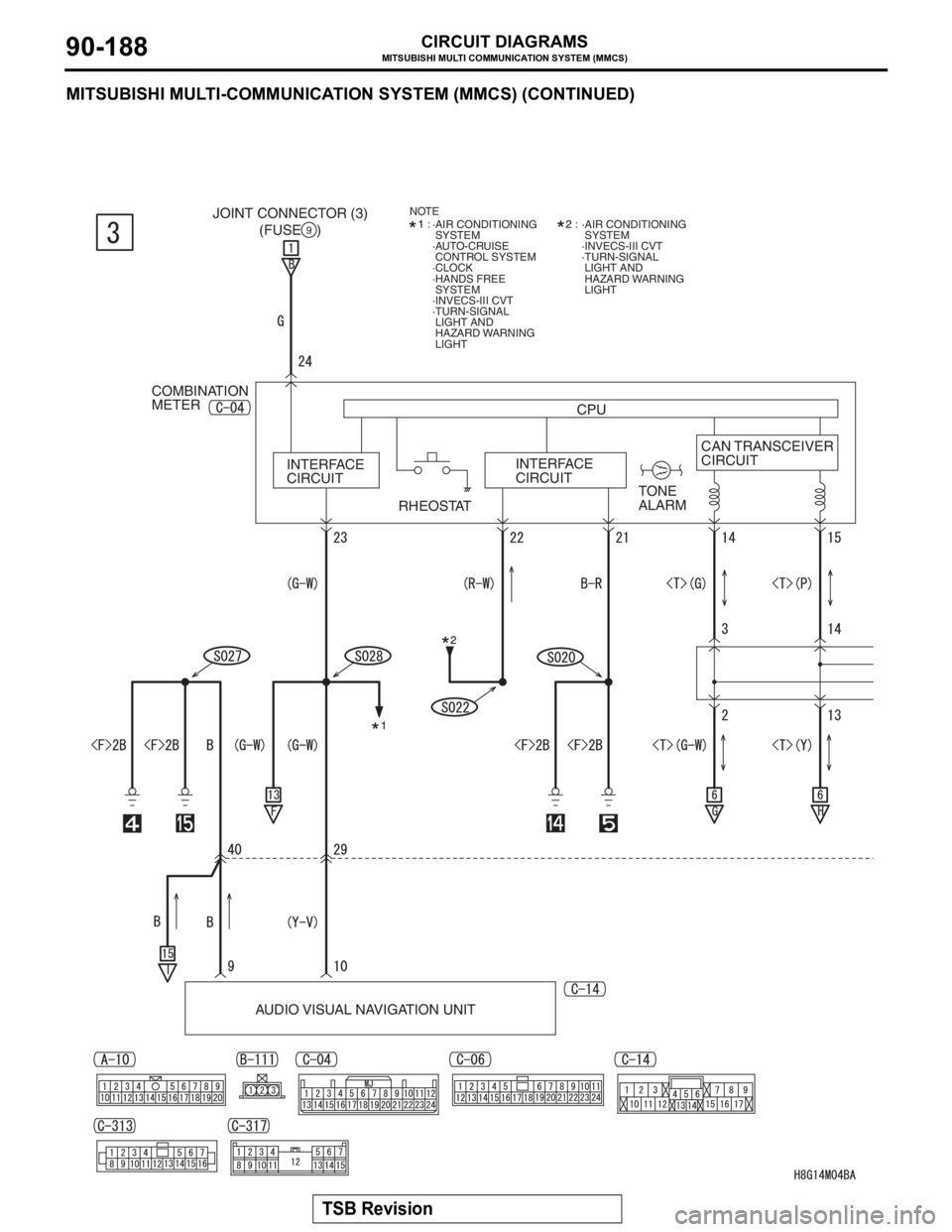
MITSUBISHI MULTI COMMUNICATION SYSTEM (MMCS)
TSB Revision
CIRCUIT DIAGRAMS90-188
MITSUBISHI MULTI-COMMUNICATION SYSTEM (MMCS) (CONTINUED)
COMBINATION
METER
INTERFACE
CIRCUITCAN TRANSCEIVER
CIRCUIT CPU (FUSE )
9
RHEOSTATTONE
ALARM INTERFACE
CIRCUIT
AUDIO VISUAL NAVIGATION UNIT
·AIR CONDITIONING
SYSTEM
·AUTO-CRUISE
CONTROL SYSTEM
·CLOCK
·HANDS FREE
SYSTEM
·INVECS-III CVT
·TURN-SIGNAL
LIGHT AND
HAZARD WARNING
LIGHT:
·AIR CONDITIONING
SYSTEM
·INVECS-III CVT
·TURN-SIGNAL
LIGHT AND
HAZARD WARNING
LIGHT: NOTEJOINT CONNECTOR (3)
Page 111 of 241
SENSOR
MULTIPORT FUEL SYSTEM (MFI)13A-18
.
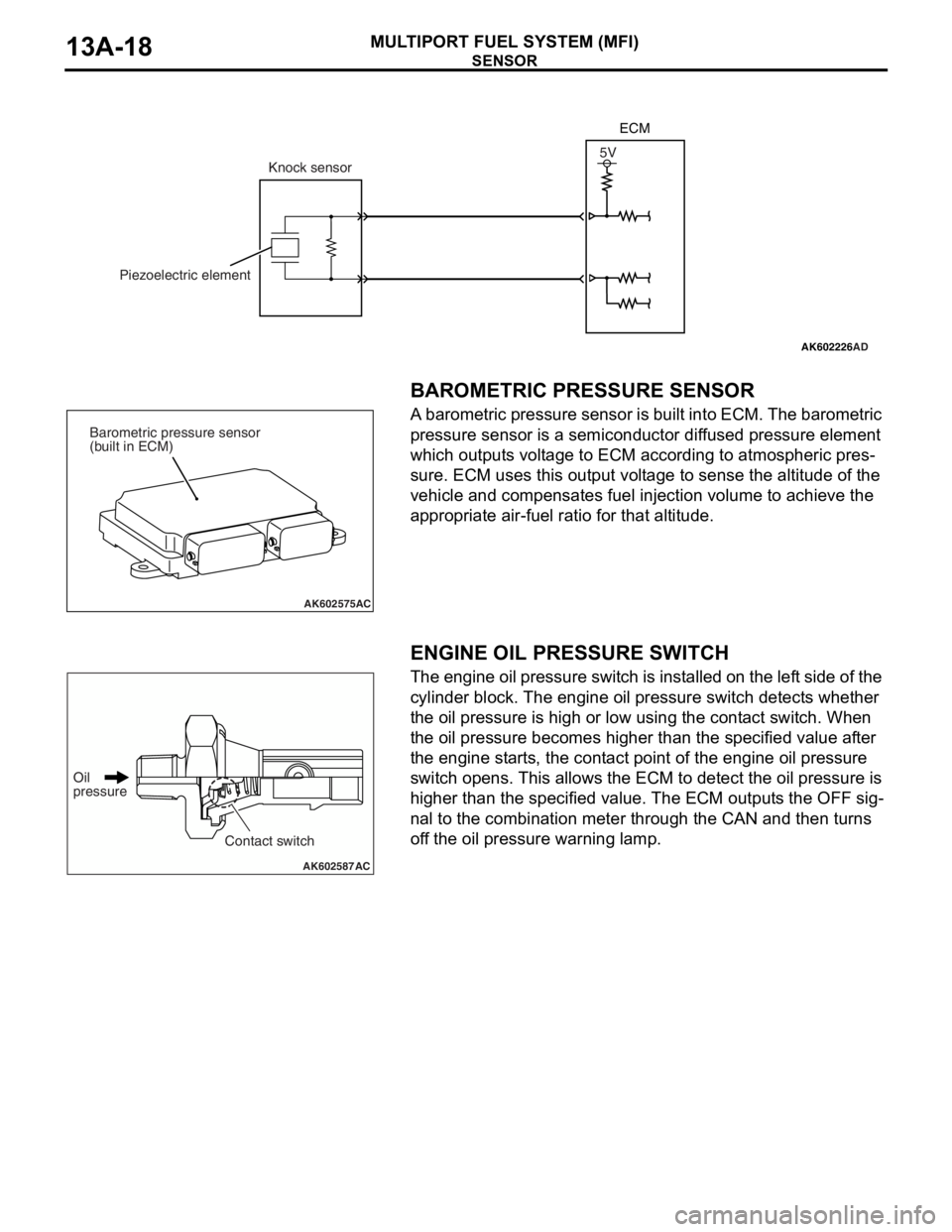
BAROMETRIC PRESSURE SENSOR
A barometric pressure sensor is built into ECM. The barometric
pressure sensor is a semiconductor diffused pressure element
which outputs voltage to ECM according to atmospheric pres
-
sure. ECM uses this output voltage to sense the altitude of the
vehicle and compensates fuel injection volume to achieve the
appropriate air-fuel ratio for that altitude.
.
ENGINE OIL PRESSURE SWITCH
The engine oil pressure switch is installed on the left side of the
cylinder block. The engine oil pressure switch detects whether
the oil pressure is high or low using the contact switch. When
the oil pressure becomes higher than the specified value after
the engine starts, the contact point of the engine oil pressure
switch opens. This allows the ECM to detect the oil pressure is
higher than the specified value. The ECM outputs the OFF sig
-
nal to the combination meter through the CAN and then turns
off the oil pressure warning lamp.
AK602226AD
5V
Knock sensor
Piezoelectric elementECM
AK602575AC
Barometric pressure sensor
(built in ECM)
AK602587AC
Oil
pressure
Contact switch
Page 157 of 241
SEAT BELT
INTERIOR52A-8
SEAT BELTM2520010000683
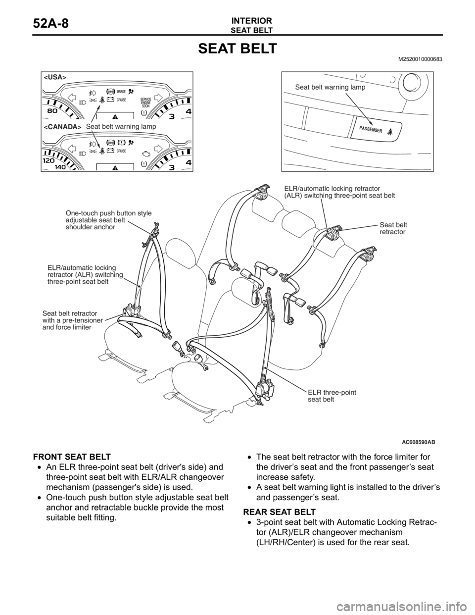
FRONT SEAT BELT
•An ELR three-point seat belt (driver's side) and
three-point seat belt with ELR/ALR changeover
mechanism (passenger's side) is used.
•One-touch push button style adjustable seat belt
anchor and retractable buckle provide the most
suitable belt fitting.
•The seat belt retractor with the force limiter for
the driver’s seat and the front passenger’s seat
increase safety.
•A seat belt warning light is installed to the driver’s
and passenger’s seat.
REAR SEAT BELT
•3-point seat belt with Automatic Locking Retrac-
tor (ALR)/ELR changeover mechanism
(LH/RH/Center) is used for the rear seat.
AC608590
Seat belt warning lamp
Seat belt warning lamp
ELR three-point
seat belt
One-touch push button style
adjustable seat belt
shoulder anchor
ELR/automatic locking
retractor (ALR) switching
three-point seat belt
Seat belt retractor
with a pre-tensioner
and force limiter ELR/automatic locking retractor
(ALR) switching three-point seat belt
Seat belt
retractor
AB
Page 162 of 241
52A-1
GROUP 52A
INTERIOR
CONTENTS
GENERAL DESCRIPTION. . . . . . . . .52A-2
SPECIAL TOOL . . . . . . . . . . . . . . . . .52A-2
INSTRUMENT PANEL ASSEMBLY*.52A-2
REMOVAL AND INSTALLATION . . . . . . . . 52A-2
GLOVE BOX . . . . . . . . . . . . . . . . . . .52A-5
REMOVAL AND INSTALLATION . . . . . . . . 52A-5
INSTRUMENT CENTER PANEL . . . .52A-6
REMOVAL AND INSTLLATION . . . . . . . . . 52A-6
INSTRUMENT LOWER PANEL. . . . .52A-7
REMOVAL AND INSTALLATION . . . . . . . . 52A-7
FLOOR CONSOLE ASSEMBLY . . . .52A-8
REMOVAL AND INSTALLATION . . . . . . . . 52A-8
TRIMS. . . . . . . . . . . . . . . . . . . . . . . . .52A-10
REMOVAL AND INSTALLATION . . . . . . . . 52A-10
DOOR TRIM . . . . . . . . . . . . . . . . . . . .52A-13
REMOVAL AND INSTALLATION . . . . . . . . 52A-13
HEADLINING . . . . . . . . . . . . . . . . . . .52A-15
REMOVAL AND INSTALLATION . . . . . . . . 52A-15
INSIDE REAR VIEW MIRROR . . . . . .52A-17
FRONT SEAT ASSEMBLY* . . . . . . . .52A-17
REMOVAL AND INSTALLATION . . . . . . . . 52A-17
INSPECTION. . . . . . . . . . . . . . . . . . . . . . . . 52A-19
DISASSEMBLY AND ASSEMBLY . . . . . . . 52A-21
REAR SEAT ASSEMBLY . . . . . . . . . .52A-23
REMOVAL AND INSTALLATION . . . . . . . . 52A-23
DISASSEMBLY AND ASSEMBLY . . . . . . . 52A-26
FRONT SEAT BELT* . . . . . . . . . . . . .52A-28
REMOVAL AND INSTALLATION . . . . . . . . 52A-28
INSPECTION. . . . . . . . . . . . . . . . . . . . . . . . 52A-29
REAR SEAT BELT . . . . . . . . . . . . . . .52A-31
REMOVAL AND INSTALLATION . . . . . . . . 52A-31
WARNINGS REGARDING SERVICING OF SUPPLEMENTAL RESTRAINT SYSTEM (SRS) EQUIPPED VEHICLES
WARNING
•Improper service or maintenance of an y component of the SRS, or any SRS-related component, can lead to
personal injury or death to service personnel (from inadvertent firing of the air bag) or to the driver and
passenger (from renderin g the SRS inoperative).
•Service or maintenance of any SRS component or SRS-related component must be performed only at an
authorized MITSUBISHI dealer.
•MITSUBISHI dealer personnel must thoroughly review this manual, and especially its GROUP 52B - Supplemental
Restraint System (SRS) before beginning any service or maintenance of any component of the SRS or any
SRS-related component.
NOTE
The SRS includes the following components: SRS air bag control unit, SRS warning light, front impact sensors, driver’s and
passenger’s (front) air bag modules, knee air bag module, side-airbag module, curtain air bag module, side impact sensors,
seat belt pre-tensioners, clock spring, and interconnecting wiring. Other SRS-related components (that may have to be
removed/installed in connection with SRS service or maintenance) are indicated in the table of contents by an asterisk (*).
Page 163 of 241
GENERAL DESCRIPTION
TSB Revision
INTERIOR52A-2
GENERAL DESCRIPTIONM1521000100429
OPERATION
.
SEAT BELT WARNING SYSTEM
If the driver turns the ignition switch to the "ON" posi-
tion without fastening the seat belt, the seat belt
warning light illuminates.
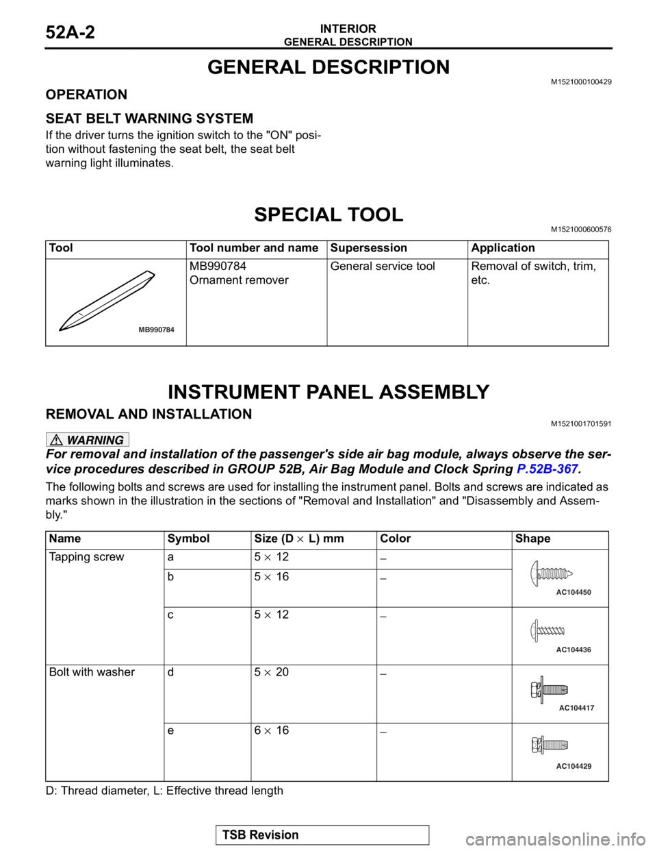
SPECIAL TOOLM1521000600576
INSTRUMENT PANEL ASSEMBLY
REMOVAL AND INSTALLATIONM1521001701591
WARNING
For removal and installation of the passenger's side air bag module, always observe the ser-
vice procedures described in GROUP 52B, Air Bag Module and Clock Spring P.52B-367.
The following bolts and screws are used for installing the in strument panel. Bolts and screws are indicated as
marks shown in the illustration in the sections of "R emoval and Installation" and "Disassembly and Assem
-
bly."
D: Thread diameter, L: Effective thread length
ToolTool number and nameSupersessionApplication
MB990784
Ornament remover
General service toolRemoval of switch, trim,
etc.
MB990784
NameSymbolSize (D × L) mmColorShape
Tapping screwa5 × 12−
b5 × 16−
c5 × 12−
Bolt with washerd5 × 20−
e6 × 16−
AC104450
AC104436
AC104417
AC104429
Page 178 of 241
INSIDE REAR VIEW MIRROR
TSB Revision
INTERIOR52A-17
INSIDE REAR VIEW MIRRORM1521002600561
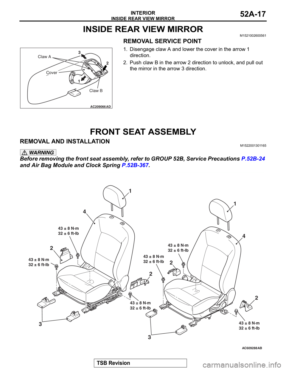
REMOVAL SERVICE POINT
1. Disengage claw A and lower the cover in the arrow 1 direction.
2. Push claw B in the arrow 2 direction to unlock, and pull out the mirror in the arrow 3 direction.
FRONT SEAT ASSEMBLY
REMOVAL AND INSTALLATIONM1522001301165
WARNING
Before removing the front seat assembly, refer to GROUP 52B, Service Precautions P.52B-24
and Air Bag Module and Clock Spring P.52B-367.
AC209066
Claw B
Claw A
Cover
12
3
AD
AC609288AB
4
3 1
43 ± 8 N·m
32 ± 6 ft-lb
43 ± 8 N·m
32 ± 6 ft-lb
43 ± 8 N·m
32 ± 6 ft-lb
43 ± 8 N·m
32 ± 6 ft-lb 43 ± 8 N·m
32 ± 6 ft-lb
43 ± 8 N·m
32 ± 6 ft-lb
1
4
2
2
2
3
2
Page 212 of 241

GENERAL INFORMATION
FOUR-WHEEL ANTI-LOCK BRAKE SYSTEM (4ABS)35B-3
MAIN COMPONENTS AND FUNCTIONS
.
Parts nameNo.Functional description
SensorWheel speed sensor1Outputs the frequency signal in proportion to the
rotation speed of each wheel to ABS-ECU.
Magnetic encoder for
wheel speed detection2The wheel speed sensor is a pulse generator. When
the magnetic encoder for wheel speed detection (a
plate on which north and south pole sides of the
magnets are arranged alternately) rotates, it outputs
frequency pulse signal in proportion to each wheel
speed.
Stop light switch3Outputs the signal indicating whether the brake pedal
is depressed or not through ETACS-ECU to ABS-ECU
via the CAN line.
ActuatorHydraulic unit4Drives the solenoid valve using the signal from
ABS-ECU, and controls the brake fluid pressure for
each wheel.
ABS warning light5Informs the driver of the system status by illuminating,
flashing, or turning off the warning light according to
the signal from ABS-ECU.
Brake warning light6Used as the warning light for the parking brake, brake
fluid level, and EBD control. Informs the driver of the
system status by illuminating or turning off the warning
light according to the signal from ABS-ECU, ETACS or
combination meter.
Data link connector7Establishes the communication with scan tool.
ABS control unit (ABS-ECU)8Controls the actuators (described above) based on the
signals coming from each sensors.
Controls the self-diagnostic functions and fail-safe
functions.
Controls diagnostic function (Compatible with scan
tool).
Page 213 of 241
GENERAL INFORMATION
FOUR-WHEEL ANTI-LOCK BRAKE SYSTEM (4ABS)35B-4
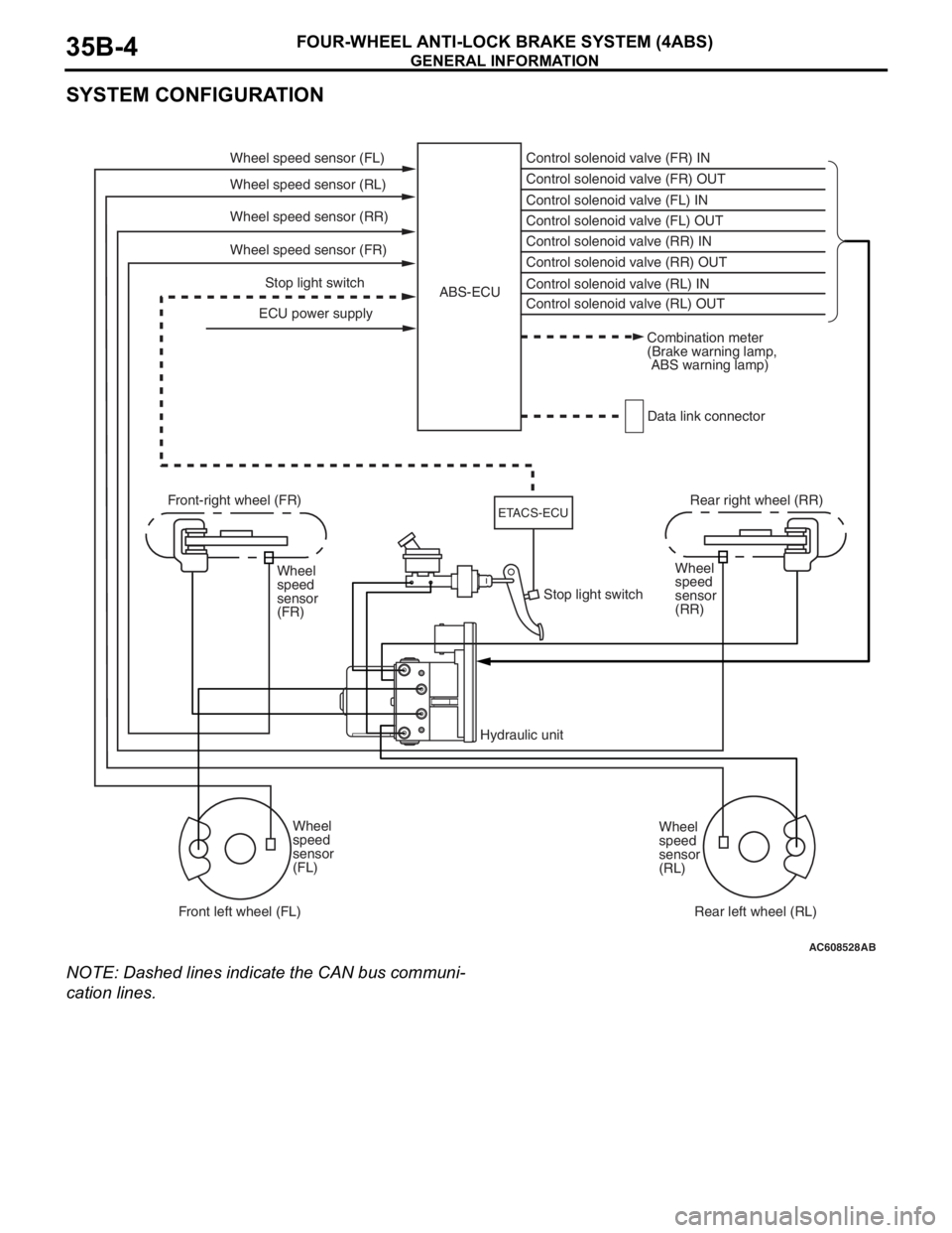
SYSTEM CONFIGURATION
NOTE: Dashed lines indicate the CAN bus communi-
cation lines.
.
AC608528AB
Wheel speed sensor (FL)
ECU power supplyABS-ECU
Combination meter
(Brake warning lamp,
ABS warning lamp)
Data link connector Wheel speed sensor (RL)
Wheel speed sensor (RR)
Wheel speed sensor (FR)
Stop light switch Front-right wheel (FR)
Hydraulic unit Stop light switch
ETACS-ECU
Wheel
speed
sensor
(FL) Wheel
speed
sensor
(FR)Wheel
speed
sensor
(RR)
Wheel
speed
sensor
(RL) Control solenoid valve (RL) OUT Control solenoid valve (RR) OUT Control solenoid valve (FL) OUT Control solenoid valve (FR) OUT Control solenoid valve (FR) IN
Control solenoid valve (FL) IN
Control solenoid valve (RR) IN
Control solenoid valve (RL) IN
Rear right wheel (RR)
Rear left wheel (RL) Front left wheel (FL)
Page 215 of 241
CONSTRUCTION DESCRIPTION
FOUR-WHEEL ANTI-LOCK BRAKE SYSTEM (4ABS)35B-6
CONSTRUCTION DESCRIPTION
SENSORM2351001000494
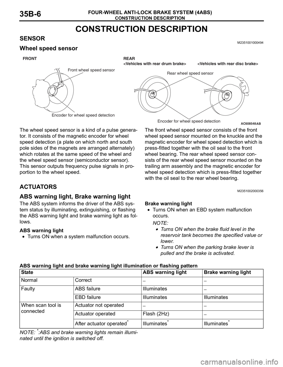
Wheel speed sensor
The wheel speed sensor is a kind of a pulse genera-
tor. It consists of the magnetic encoder for wheel
speed detection (a plate on which north and south
pole sides of the magnets are arranged alternately)
which rotates at the same speed of the wheel and
the wheel speed sensor (semiconductor sensor).
This sensor outputs frequency pulse signals in pro
-
portion to the wheel speed.
The front wheel speed sensor consists of the front
wheel speed sensor mounted on the knuckle and the
magnetic encoder for wheel speed detection which is
press-fitted together with the oil seal to the front
wheel bearing. The rear wheel speed sensor con
-
sists of the rear wheel speed sensor mounted on the
trailing arm assembly and the magnetic encoder for
wheel speed detection which is press-fitted together
with the oil seal to the rear wheel bearing.
ACTUATORSM2351002000356
ABS warning light, Brake warning light
The ABS system informs the driver of the ABS sys-
tem status by illuminating, extinguishing, or flashing
the ABS warning light and brake warning light as fol
-
lows.
ABS warning light
•Turns ON when a system malfunction occurs.
Brake warning light
•Turns ON when an EBD system malfunction
occurs.
NOTE: .
•Turns ON when the brake fluid level in the
reservoir tank becomes the specified value or
lower.
•Turns ON when the parking brake lever is
pulled and the brake is activated.
ABS warning light and brake warning light illumination or flashing pattern
NOTE: *:ABS and brake warning lights remain illumi-
nated until the ignition is switched off.
AC608548
AB
FRONT REAR
Front wheel speed sensor
Rear wheel speed sensor
Encoder for wheel speed detection
Encoder for wheel speed detection
StateABS warning lightBrake warning light
NormalCorrect−−
FaultyABS failureIlluminates−
EBD failureIlluminatesIlluminates
When scan tool is
connectedActuator not operated−−
Actuator operatedFlash (2Hz)−
After actuator operated*Illuminates*Illuminates*
Page 216 of 241
CONSTRUCTION DESCRIPTION
FOUR-WHEEL ANTI-LOCK BRAKE SYSTEM (4ABS)35B-7
ABS-ECUM2351003000520
•By integrating ABS-ECU into the hydraulic unit,
no wiring harness for sending drive signal of the
solenoid valve and pump motor is required,
assuring higher reliability.
•Self-diagnostic and memory functions are inte-
grated into ABS-ECU. If any malfunction is
detected by the self-diagnostic function,
ABS-ECU activates a fail-safe function and illumi
-
nates the ABS warning light and brake warning
light
*.
NOTE: *: The brake warning light is used as the
EBD control warning light.
•ABS-ECU detects vehicle speed from the signals
of the wheel speed sensor and its recognizes the
wheel rotation status, estimates the wheel slip
condition based on the preprogrammed algo
-
rithm, and then controls the solenoid valve in the
hydraulic unit so that the wheels do not lock.
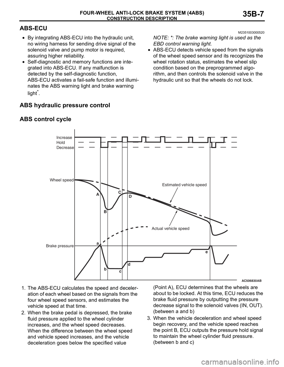
ABS hydraulic pressure control
ABS control cycle
1. The ABS-ECU calculates the speed and deceler-
ation of each wheel based on the signals from the
four wheel speed sensors, and estimates the
vehicle speed at that time.
2. When the brake pedal is depressed, the brake
fluid pressure applied to the wheel cylinder
increases, and the wheel speed decreases.
When the difference between the wheel speed
and vehicle speed increases, and the vehicle
deceleration goes below the specified value (Point A), ECU determines that the wheels are
about to be locked. At this time, ECU reduces the
brake fluid pressure by outputting the pressure
decrease signal to the solenoid valves (IN, OUT).
(between a and b)
3. When the vehicle deceleration and wheel speed
begin recovery, and the vehicle speed reaches
the point B, ECU outputs the pressure hold signal
to maintain the wheel cylinder fluid pressure.
(between b and c)
AC506830AB
a
b
cd A
BC
D
e Increase
Hold
Decrease
Wheel speed
Brake pressureActual vehicle speedEstimated vehicle speed