lock MITSUBISHI LANCER EVOLUTION X 2008 Owner's Manual
[x] Cancel search | Manufacturer: MITSUBISHI, Model Year: 2008, Model line: LANCER EVOLUTION X, Model: MITSUBISHI LANCER EVOLUTION X 2008Pages: 241, PDF Size: 8.26 MB
Page 118 of 241
ACTUATOR
MULTIPORT FUEL SYSTEM (MFI)13A-25
IGNITION COIL
Refer to GROUP 16 − Ignition Coil P.16-2.
EXHAUST GAS RECIRCULATION (EGR) VALVE
Refer to GROUP 17 − Emission Control − Exhaust Gas Recircu-
lation (EGR) System P.17-12.
EVAPORATIVE EMISSION PURGE SOLENOID
Refer to GROUP 17 − Emission Control − Evaporative Emission
Control System
P.17-11.
INTAKE ENGINE OIL CONTROL VALVE
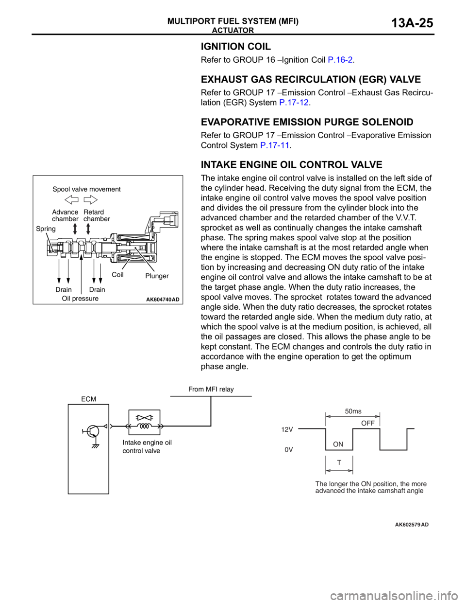
The intake engine oil control valve is installed on the left side of
the cylinder head. Receiving the duty signal from the ECM, the
intake engine oil control valve moves the spool valve position
and divides the oil pressure from the cylinder block into the
advanced chamber and the retarded chamber of the V.V.T.
sprocket as well as continually changes the intake camshaft
phase. The spring makes spool valve stop at the position
where the intake camshaft is at the most retarded angle when
the engine is stopped. The ECM moves the spool valve posi
-
tion by increasing and decreasing ON duty ratio of the intake
engine oil control valve and allows the intake camshaft to be at
the target phase angle. When the duty ratio increases, the
spool valve moves. The sprocket rotates toward the advanced
angle side. When the duty ratio decreases, the sprocket rotates
toward the retarded angle side. When the medium duty ratio, at
which the spool valve is at the medium position, is achieved, all
the oil passages are closed. This allows the phase angle to be
kept constant. The ECM changes and controls the duty ratio in
accordance with the engine operation to get the optimum
phase angle.
AK604740AD
Spool valve movement
Retard
chamber
Spring
Drain
Oil pressureCoil
Plunger
Drain Advance
chamber
AK602579
ECM
Intake engine oil
control valve12VOFF
ON
T50ms
0V
AD
From MFI relay
The longer the ON position, the more
advanced the intake camshaft angle
Page 119 of 241
ACTUATOR
MULTIPORT FUEL SYSTEM (MFI)13A-26
EXHAUST ENGINE OIL CONTROL VALVE
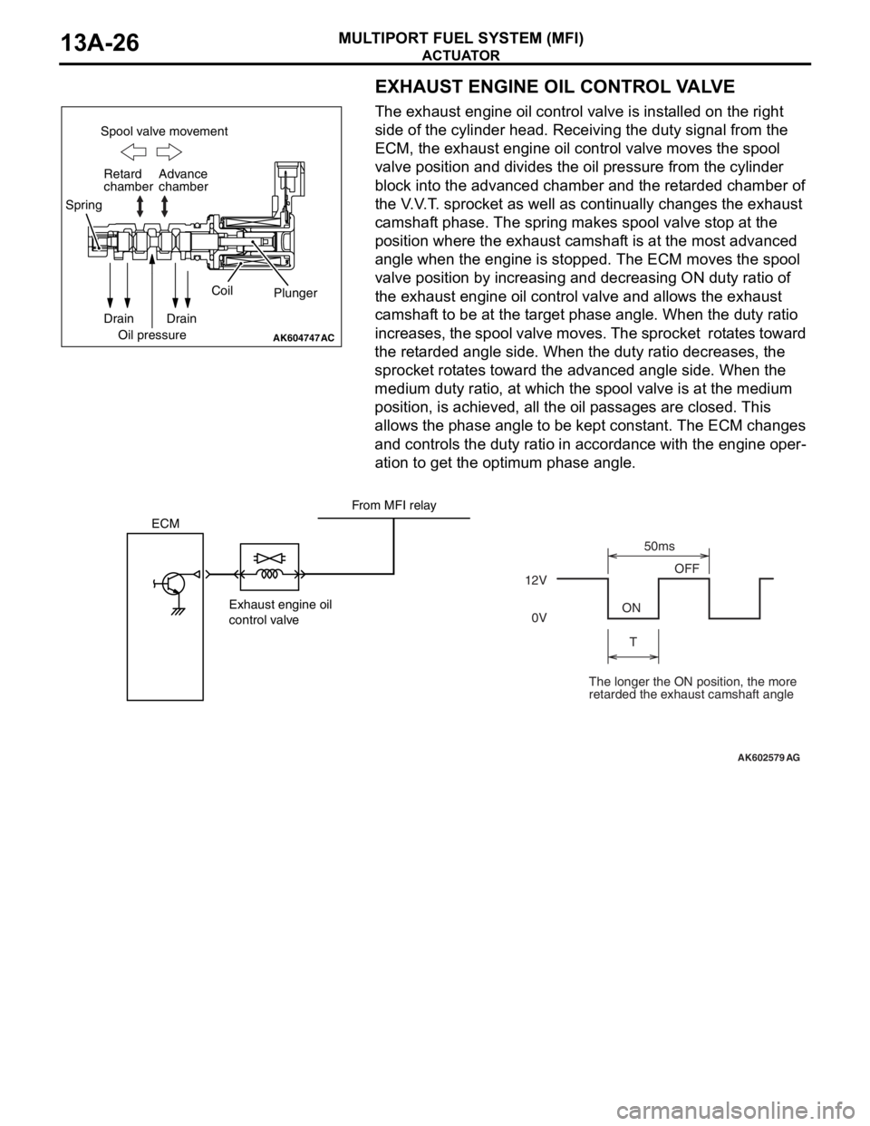
The exhaust engine oil control valve is installed on the right
side of the cylinder head. Receiving the duty signal from the
ECM, the exhaust engine oil control valve moves the spool
valve position and divides the oil pressure from the cylinder
block into the advanced chamber and the retarded chamber of
the V.V.T. sprocket as well as continually changes the exhaust
camshaft phase. The spring makes spool valve stop at the
position where the exhaust camshaft is at the most advanced
angle when the engine is stopped. The ECM moves the spool
valve position by increasing and decreasing ON duty ratio of
the exhaust engine oil control valve and allows the exhaust
camshaft to be at the target phase angle. When the duty ratio
increases, the spool valve moves. The sprocket rotates toward
the retarded angle side. When the duty ratio decreases, the
sprocket rotates toward the advanced angle side. When the
medium duty ratio, at which the spool valve is at the medium
position, is achieved, all the oil passages are closed. This
allows the phase angle to be kept constant. The ECM changes
and controls the duty ratio in accordance with the engine oper
-
ation to get the optimum phase angle.
AK604747
Spool valve movement
Retard
chamber
Spring
Drain
Oil pressureCoil
Plunger
Drain Advance
chamber
AC
AK602579
ECM
Exhaust engine oil
control valve12VOFF
ON
T50ms
0V
AG
From MFI relay
The longer the ON position, the more
retarded the exhaust camshaft angle
Page 125 of 241
FUEL INJECTION CONTROL
MULTIPORT FUEL SYSTEM (MFI)13A-32
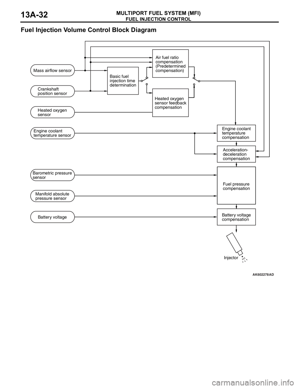
Fuel Injection Volume Control Block Diagram
.
AK602278AD
Mass airflow sensor
Crankshaft
position sensor
Heated oxygen
sensor
Engine coolant
temperature
compensation Engine coolant
temperature sensor
Manifold absolute
pressure sensorFuel pressure
compensation Barometric pressure
sensor
Battery voltage
compensation Battery voltageBasic fuel
injection time
determinationAir fuel ratio
compensation
(Predetermined
compensation)
Heated oxygen
sensor feedback
compensation
Injector Acceleration-
deceleration
compensation
Page 138 of 241
MULTIPORT FUEL INJECTION (MFI) RELAY CONTROL
MULTIPORT FUEL SYSTEM (MFI)13A-45
MULTIPORT FUEL INJECTION (MFI) RELAY CONTROLM2132006000173
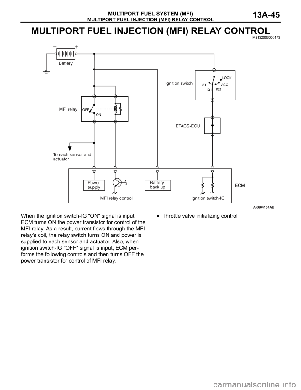
When the ignition switch-IG "ON" signal is input,
ECM turns ON the power transistor for control of the
MFI relay. As a result, current flows through the MFI
relay's coil, the relay switch turns ON and power is
supplied to each sensor and actuator. Also, when
ignition switch-IG "OFF" signal is input, ECM per
-
forms the following controls and then turns OFF the
power transistor for control of MFI relay.
•Throttle valve initializing control
AK604134AB OFF
ON
IG2 STLOCK
ACC
IG1
MFI relay
Power
supply
MFI relay control Ignition switch-IGBattery
back up To each sensor and
actuatorIgnition switch
ETACS-ECU Battery
ECM
Page 139 of 241
FUEL PUMP RELAY CONTROL
MULTIPORT FUEL SYSTEM (MFI)13A-46
FUEL PUMP RELAY CONTROLM2132006500208
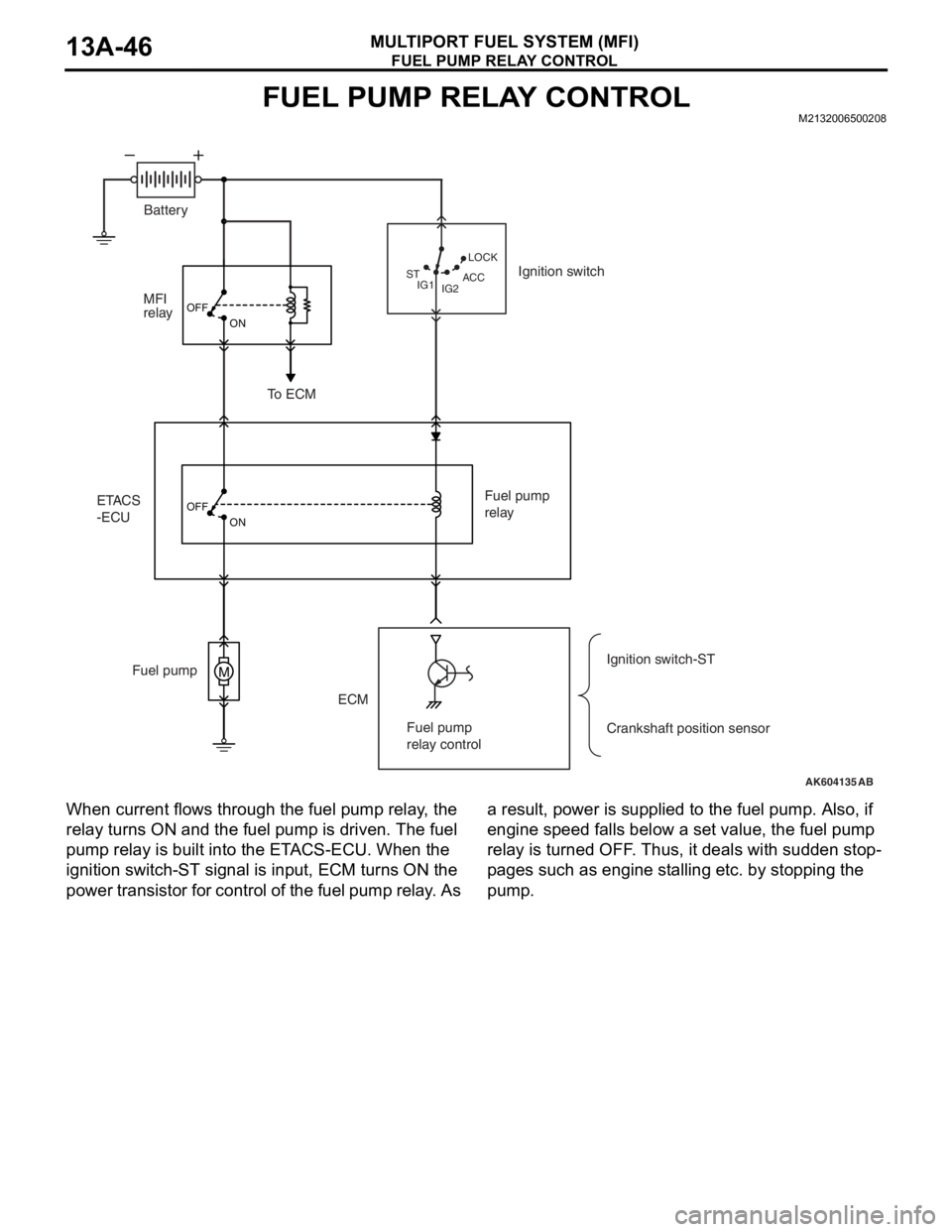
When current flows through the fuel pump relay, the
relay turns ON and the fuel pump is driven. The fuel
pump relay is built into the ETACS-ECU. When the
ignition switch-ST signal is input, ECM turns ON the
power transistor for control of the fuel pump relay. As a result, power is supplied to the fuel pump. Also, if
engine speed falls below a set value, the fuel pump
relay is turned OFF. Thus, it deals with sudden stop
-
pages such as engine stalling etc. by stopping the
pump.
AK604135
M
OFF
ON
OFF
ON
AB IG2 STLOCK
ACC
IG1
ETACS
-ECUMFI
relay
ECM Fuel pumpFuel pump
relay
Crankshaft position sensor Ignition switch
To ECM
Ignition switch-ST Battery
Fuel pump
relay control
Page 140 of 241
STARTER RELAY CONTROL
MULTIPORT FUEL SYSTEM (MFI)13A-47
STARTER RELAY CONTROLM2132025500092
AK604136
M
AB OFF ON OFF
ON
Engine-ECU
Starter relay
controlClutch
interlock
switch
ETACS
-ECUIgnition switch-STBattery
Starter relay
Starter
OFFON
Page 147 of 241
GENERAL DESCRIPTION
ENGINE LUBRICATION12-2
GENERAL DESCRIPTIONM2120000100249
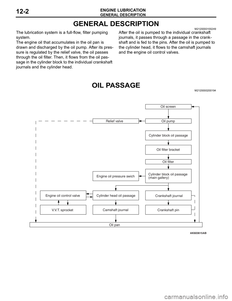
The lubrication system is a full-flow, filter pumping
system.
The engine oil that accumulates in the oil pan is
drawn and discharged by the oil pump. After its pres
-
sure is regulated by the relief valve, the oil passes
through the oil filter. Then, it flows from the oil pas
-
sage in the cylinder block to the individual crankshaft
journals and the cylinder head.
After the oil is pumped to the individual crankshaft
journals, it passes through a passage in the crank
-
shaft and is fed to the pins. After the oil is pumped to
the cylinder head, it flows to the camshaft journals
and the engine oil control valves.
OIL PASSAGEM2120000200194
AK603615
Oil screen
Oil pan Relief valve
V.V.T. sprocket Engine oil control valveOil pump
Oil filter
Engine oil pressure swichOil filter bracket Cylinder block oil passage
Crankshaft journal
Camshaft journal
Crankshaft pin Cylinder block oil passage
(main gallery)
Cylinder head oil passage
AB
Page 148 of 241
OIL FILTER
ENGINE LUBRICATION12-3
OIL FILTERM2120005000195
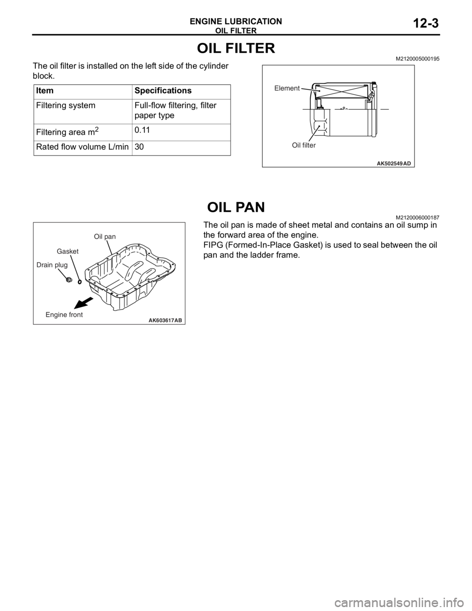
The oil filter is installed on the left side of the cylinder
block.
OIL PANM2120006000187
The oil pan is made of sheet metal and contains an oil sump in
the forward area of the engine.
FIPG (Formed-In-Place Gasket) is used to seal between the oil
pan and the ladder frame.
ItemSpecifications
Filtering systemFull-flow filtering, filter
paper type
Filtering area m20.11
Rated flow volume L/min30
AK502549
Element
Oil filter
AD
AK603617
Drain plugGasketOil pan
Engine frontAB
Page 157 of 241
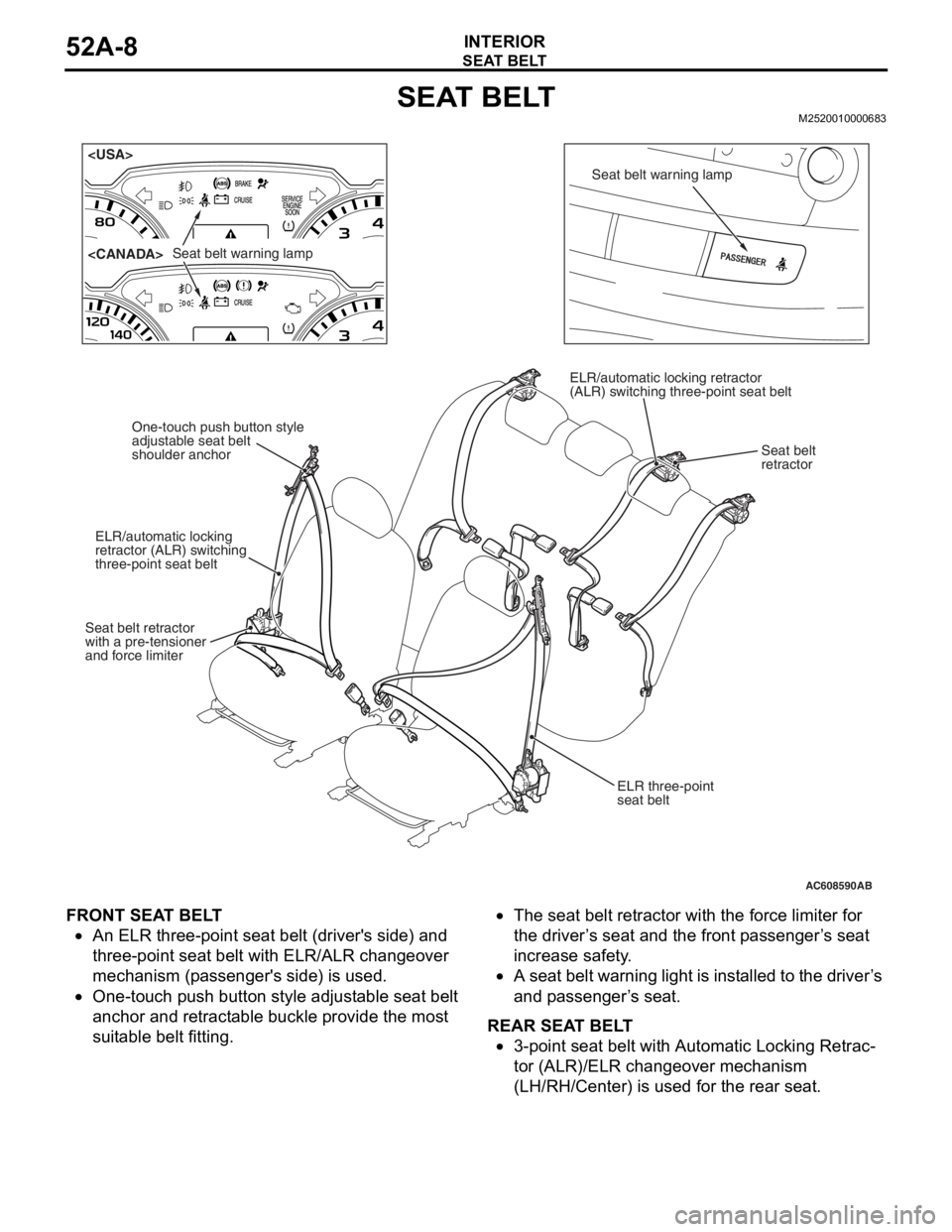
SEAT BELT
INTERIOR52A-8
SEAT BELTM2520010000683
FRONT SEAT BELT
•An ELR three-point seat belt (driver's side) and
three-point seat belt with ELR/ALR changeover
mechanism (passenger's side) is used.
•One-touch push button style adjustable seat belt
anchor and retractable buckle provide the most
suitable belt fitting.
•The seat belt retractor with the force limiter for
the driver’s seat and the front passenger’s seat
increase safety.
•A seat belt warning light is installed to the driver’s
and passenger’s seat.
REAR SEAT BELT
•3-point seat belt with Automatic Locking Retrac-
tor (ALR)/ELR changeover mechanism
(LH/RH/Center) is used for the rear seat.
AC608590
Seat belt warning lamp
Seat belt warning lamp
ELR three-point
seat belt
One-touch push button style
adjustable seat belt
shoulder anchor
ELR/automatic locking
retractor (ALR) switching
three-point seat belt
Seat belt retractor
with a pre-tensioner
and force limiter ELR/automatic locking retractor
(ALR) switching three-point seat belt
Seat belt
retractor
AB
Page 158 of 241

SEAT BELT
INTERIOR52A-9
SEAT BELT RETRACTOR WITH FORCE LIMITER
.The driver’s/front passenger’s seat belt retractor has been
equipped with a force limiter. The force limiter is a device which
operates when a predetermined force is applied, and limits the
force.
.
OPERATION
1. If a collision energy is transmi tted to the seat belt, the ELR
mechanism will operate to lock the seat belt.
2. If the energy increases to a predetermined value, the torsion bar will be distorted. As the spindle rotates together with the
torsion bar, the seat belt w ebbing is pulled out, reducing the
impact to the occupants.
AC100083
TORSION BAR
SPINDLE
BELT
AB