cooling MITSUBISHI LANCER EVOLUTION X 2008 Workshop Manual
[x] Cancel search | Manufacturer: MITSUBISHI, Model Year: 2008, Model line: LANCER EVOLUTION X, Model: MITSUBISHI LANCER EVOLUTION X 2008Pages: 241, PDF Size: 8.26 MB
Page 34 of 241

GENERAL DESCRIPTION
HEATER, AIR CONDITIONING AND VENTILATION55-2
GENERAL DESCRIPTIONM2551001500040
The blower, heater, and evaporator have been inte-
grated with the heater and A/C system to achieve a
greater fan power and noise reduction.
FEATURES
.
ENHANCEMENTS IN COMFORT
•With the adoption of fully-automatic A/C, the out-
side/inside air circulation switching, air outlet, and
outlet air temperature are automatically con
-
trolled according to the ambient temperature,
solar radiation, and passenger compartment tem
-
perature so that the optimum air conditioner is
achieved.
•By the adoption of clean air filter, the air quality
inside the passenger compartment has been
enhanced.
.
ENHANCEMENTS IN OPERATION
PERFORMANCE
•Operability has been enhanced by the adoption
of large triple dial.
•Customise function has been added for the
enhanced convenience.
.
ENHANCEMENTS IN FUEL ECONOMY
•The high efficiency compressor with a 2-step pro-
file oil separator has been installed, thus enhanc-
ing the fuel economy.
•The idle-up speed is controlled in two steps to
secure the air cooling performance during sum
-
mer and to enhance the fuel economy in the sea-
sons with moderate temperature.
•Enhancement of fuel economy by the cooling fan
control depending on the refrigerant pressure and
vehicle speed.
.
ENHANCEMENT IN SAFETY
•A/C system is stopped when the air bags are
deployed.
•Crushable space has been adopted to heater unit
to reduce the risk of passenger injuries in case of
a collision.
.
GLOBAL ENVIRONMENT PROTECTION
•New refrigerant system (HFC134a) has been
adopted.
•By the optimisation of A/C system, the refrigerant
charging amount has been reduced.
•Clean air filter media and its cover are separated
to reduce waste materials.
.
ENHANCEMENTS IN SERVICE QUALITY
•Reduction of refrigerant gas leakage and
enhancement in serviceability by incorporating
condenser and receiver
•Clean air filter is installed to the backside of glove
box to facilitate the filter replacement.
.
ENHANCEMENTS IN RESPONSIBILITY
Reliable information transmission is achieved by
connecting A/C-ECU and each ECU via CAN com
-
munication.
SPECIFICATIONS
ITEMSPECIFICATION
Air conditioning switch typeRotary type
Compressor typeMSC90CAS
Cooling output5.5 kw
Heating output5.7 kw
RefrigerantTy p eR134a (HFC-134a)
Charge quantity g (oz.)480 - 520 (16.9 - 18.3)
Page 37 of 241
HEATER AND AIR CONDITIONING SYSTEM
HEATER, AIR CONDITIONING AND VENTILATION55-5
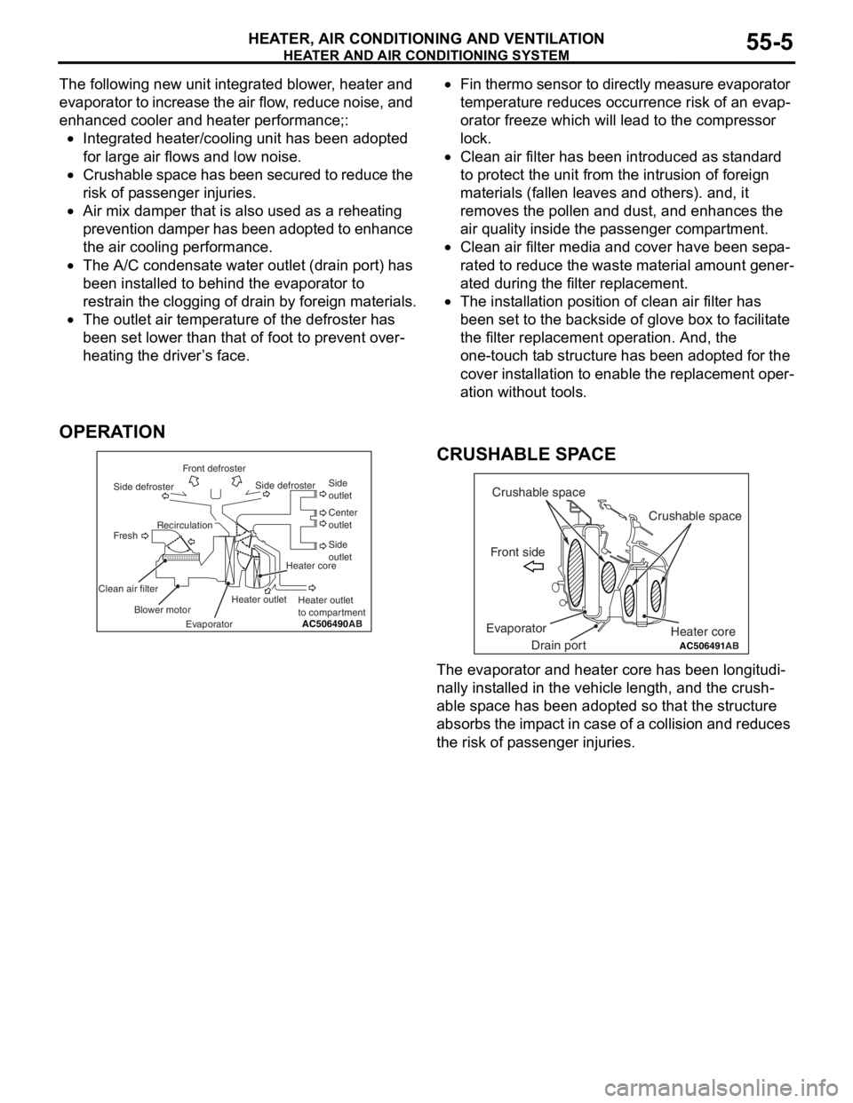
The following new unit integrated blower, heater and
evaporator to increase the air flow, reduce noise, and
enhanced cooler and heater performance;:
•Integrated heater/cooling unit has been adopted
for large air flows and low noise.
•Crushable space has been secured to reduce the
risk of passenger injuries.
•Air mix damper that is also used as a reheating
prevention damper has been adopted to enhance
the air cooling performance.
•The A/C condensate water outlet (drain port) has
been installed to behind the evaporator to
restrain the clogging of drain by foreign materials.
•The outlet air temperature of the defroster has
been set lower than that of foot to prevent over
-
heating the driver’s face.
•Fin thermo sensor to directly measure evaporator
temperature reduces occurrence risk of an evap
-
orator freeze which will lead to the compressor
lock.
•Clean air filter has been introduced as standard
to protect the unit from the intrusion of foreign
materials (fallen leaves and others). and, it
removes the pollen and dust, and enhances the
air quality inside the passenger compartment.
•Clean air filter media and cover have been sepa-
rated to reduce the waste material amount gener-
ated during the filter replacement.
•The installation position of clean air filter has
been set to the backside of glove box to facilitate
the filter replacement operation. And, the
one-touch tab structure has been adopted for the
cover installation to enable the replacement oper
-
ation without tools.
OPERATION
.
CRUSHABLE SPACE
The evaporator and heater core has been longitudi-
nally installed in the vehicle length, and the crush-
able space has been adopted so that the structure
absorbs the impact in case of a collision and reduces
the risk of passenger injuries.
AC506490AB Front defroster
Side defrosterSide defrosterSide
outlet
Side
outlet Center
outlet
Heater core
Heater outlet
to compartment Recirculation
Fresh
Clean air filter
Blower motor
EvaporatorHeater outlet
AC506491
Crushable space
Crushable space
Front side
Drain port EvaporatorHeater coreAB
Page 39 of 241

A/C-ECU
HEATER, AIR CONDITIONING AND VENTILATION55-7
A/C-ECUM2551001200265
CONTROL
.
FORCED DEF CONTROL
When air outlet position is switched to DEF, A/C is
automatically turned ON, and outside/inside air
selection damper is set to the fresh air position to
quickly defrost the windshield screen.
.
MAX A/C CONTROL
When the temperature adjustment knob is turned to
the maximum A/C position with the blower knob at
position other than OFF, the following controls are
made by the A/C-ECU.
NOTE: "*" Manual operation is disabled during max
A/C control.
.
MAX COOL, MAX HOT CONTROL
When the set temperature is at 18.0 °C <61°F>
(MAX COOL) or at 32.0
°C <89°F> (MAX HOT) with
the air outlet and air volume at the AUTO positions,
the following controls are made automatically by the
A/C-ECU.
NOTE: "*" indicates that when the automatic control
is not cancelled using the customise function, the
manual operation is disabled.
.
REAR WINDOW DEFOGGER TIMER
CONTROL
In order to prevent battery consumption, the defog-
ger is automatically turned OFF, 20 minutes after it is
turned ON.
.
IDLE-UP CONTROL
A/C-ECU and the engine ECU communicate with
each other through the CAN communication. The
idle-up speed of the engine is controlled in two steps
depending on the A/C load to secure the air cooling
performance during summer and to enhance fuel
economy in seasons with moderate temperature.
.
DETECTION CONTROL FOR
REFRIGERANT LEAKS
A/C-ECU determines if the refrigerant amount is less
than specified or refrigerant pressure is abnormal by
using the ambient temperature (ambient temperature
sensor to measure refrigerant inflation rate) and
refrigerant pressure (measured by the A/C pressure
sensor). When refrigerant amount or refrigerant pres
-
sure is judged abnormal, the compressor is cut-off to
protect the A/C system.
NOTE: When abnormality occurs, the A/C indicator
flashes.
.
PROTECTION CONTROL AT AIR BAG
DEPLOYMENT (DURING COLLISION)
When the air bag deployment is detected, the A/C
system is stopped.
.
CUSTOMISE FUNCTION
Depending on the user's preference, the following
functions can be selected. The programmed informa
-
tion is held even when the battery is disconnected.
•Automatic control for inside/outside air selection
Press and hold (approximately for 10 seconds)
the inside/outside air selection switch to cancel
the automatic control for inside/outside air selec
-
tion.
•A/C automatic control
Press and hold (approximately for 10 seconds)
the A/C switch to cancel the A/C automatic con
-
trol.
Subject to controlMAX COOL
Air mix damperMAX COOL position
Air outlet modeSelected position
Air volumeSelected position
Outside/inside air
selection damperAir recirculation position*
Air conditioner switchON*
Subject to
controlMAX COOLMAX HOT
Air mix
damperMAX COOL
positionMAX HOT
position
Air outlet
modeFACE positionFOOT position
Air volumeMaximumMaximum
Outside/insid
e air
selection
damperAir recirculation
position*Fresh air
position*
Air
conditioner
switchON*OFF*
Page 41 of 241
A/C COMPRESSOR
HEATER, AIR CONDITIONING AND VENTILATION55-9
A/C COMPRESSORM2551001100268
HIGH EFFICIENCY COMPRESSOR WITH
INTEGRATED OIL SEPARATOR
High efficiency compressor with integrated oil sepa-
rator has been adopted to enhance fuel economy by
reducing the A/C operating rate.
MAGNETIC CLUTCH WITH THERMAL
FUSE
At the compressor lock, the thermal fuse integrated
in the magnet clutch is blown due to the frictional
heat against the compressor in order to reduce risk
of the drive belt breakage. The thermal fuse, together
with the coil, is coated with resin to enhance resis
-
tance to corrosion.
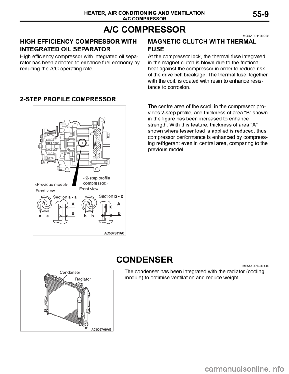
2-STEP PROFILE COMPRESSOR
The centre area of the scroll in the compressor pro-
vides 2-step profile, and thickness of area "B" shown
in the figure has been increased to enhance
strength. With this feature, thickness of area "A"
shown where lesser load is applied is reduced, thus
compressor performance is enhanced by compress
-
ing refrigerant even in central area, comparing to the
previous model.
CONDENSERM2551001400140
The condenser has been integrated with the radiator (cooling
module) to optimise ventilation and reduce weight.
AC507301
aa bbAA
BB
AC
Section a - aSection b - b Front viewFront view
compressor>
AC608768
Condenser
AB
Radiator
Page 47 of 241
BASE ENGINE
ENGINE MECHANICAL11A-3
BASE ENGINEM2112001001050
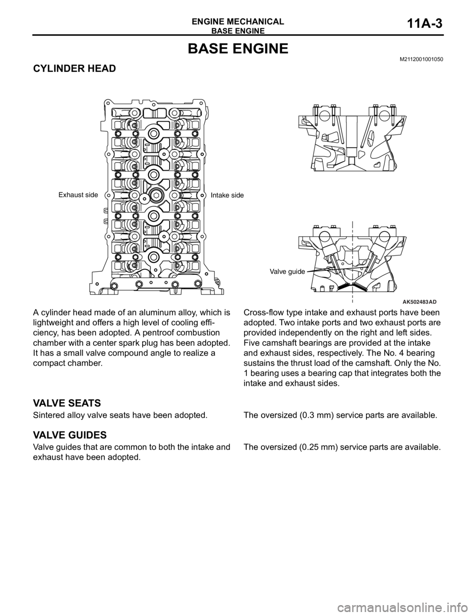
CYLINDER HEAD
A cylinder head made of an aluminum alloy, which is
lightweight and offers a high level of cooling effi
-
ciency, has been adopted. A pentroof combustion
chamber with a center spark plug has been adopted.
It has a small valve compound angle to realize a
compact chamber.
Cross-flow type intake and exhaust ports have been
adopted. Two intake ports and two exhaust ports are
provided independently on the right and left sides.
Five camshaft bearings are provided at the intake
and exhaust sides, respectively. The No. 4 bearing
sustains the thrust load of the camshaft. Only the No.
1 bearing uses a bearing cap that integrates both the
intake and exhaust sides.
VA LV E S E AT S
Sintered alloy valve seats have been adopted.The oversized (0.3 mm) service parts are available.
VA LV E G U I D E S
Valve guides that are common to both the intake and
exhaust have been adopted.The oversized (0.25 mm) service parts are available.
AK502483
Valve guide
AD
Exhaust side
Intake side
Page 84 of 241
AIR DUCT AND AIR CLEANER
INTAKE AND EXHAUST15-2
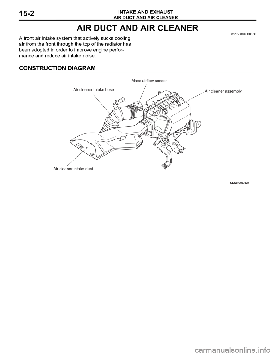
AIR DUCT AND AIR CLEANERM2150004000656
A front air intake system that actively sucks cooling
air from the front through the top of the radiator has
been adopted in order to improve engine perfor
-
mance and reduce air intake noise.
CONSTRUCTION DIAGRAM
AC608342AB
Air cleaner assembly Mass airflow sensor
Air cleaner intake hose
Air cleaner intake duct
Page 87 of 241
14-1
GROUP 14
ENGINE COOLING
CONTENTS
GENERAL INFORMATION . . . . . . . .14-2
WATER PASSAGE . . . . . . . . . . . . . .14-3
WATER PUMP . . . . . . . . . . . . . . . . . .14-3
Page 88 of 241

GENERAL INFORMATION
ENGINE COOLING14-2
GENERAL INFORMATIONM2140000100780
The cooling system is a water-cooled pressurized,
forced circulation type which offers the following fea
-
tures.
•To stabilize engine coolant temperature, the ther-
mostat is located at the coolant inlet port from the
radiator.
•To improve engine cooling performance and save
weight, a plastic tank and aluminum radiator fins
are used.
SPECIFICATIONS
CONSTRUCTION DIAGRAM
ItemSpecification
Cooling methodWater-cooled pressurized, forced
circulation with electrical fan
RadiatorTy p ePressurized corrugate type
Performance kJ/h (kcal/h)222,480 (53,148)
Water pumpTy p eCentrifugal impeller
Drive methodDrive belt
ThermostatTy p eWax pellet with jiggle valve
Valve open temperature °C (°F)82 (180)
AC608448
Condenser fan motor Radiator assemblyRadiator upper hose
assembly
Radiator condenser
tank assembly Radiator fan motor
Cooling fan shroud
Radiator lower hose Transmission oil
cooler line hose
and tube assembly
AB
Page 89 of 241
WATER PASSAGE
ENGINE COOLING14-3
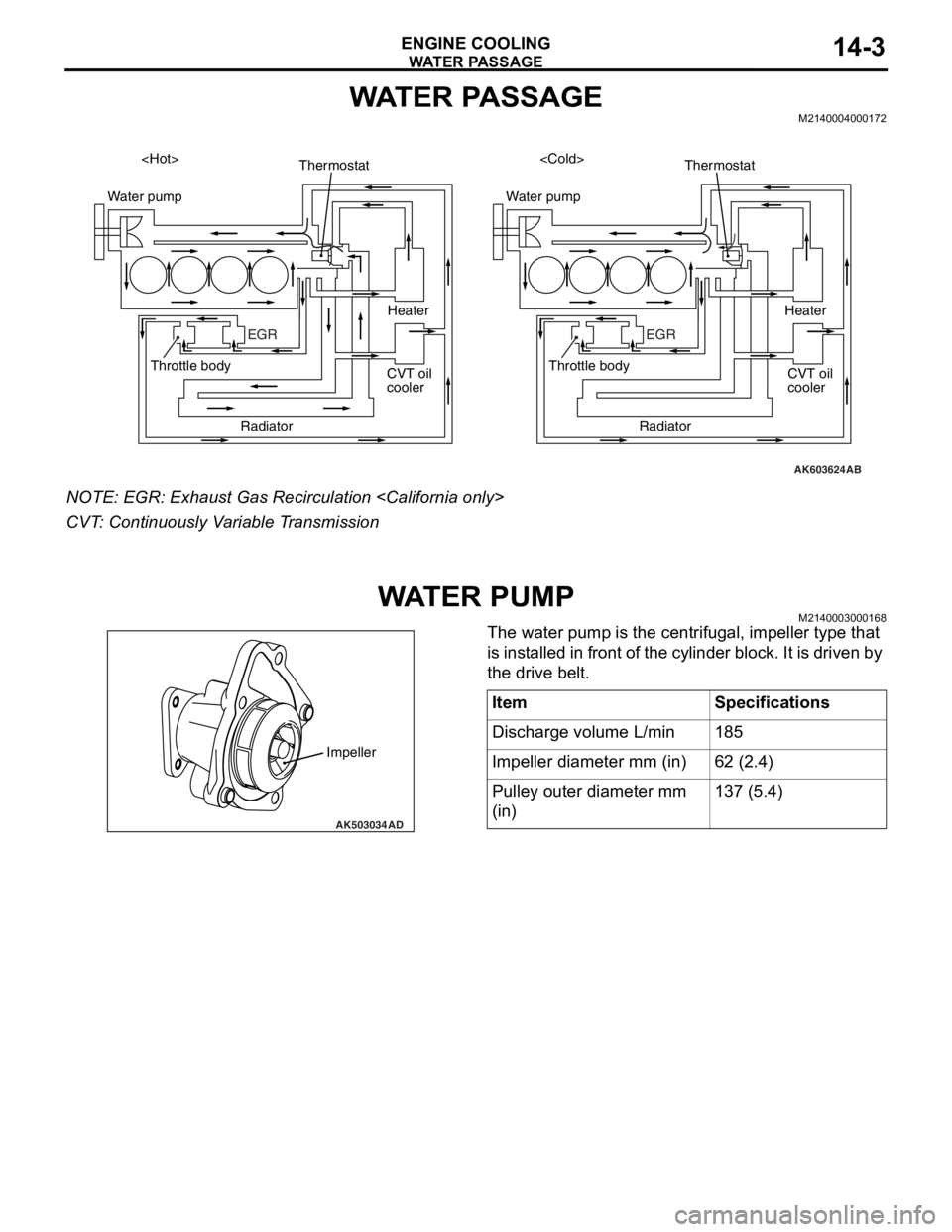
WATER PASSAGEM2140004000172
NOTE: EGR: Exhaust Gas Recirculation
CVT: Continuously Variable Transmission
WAT E R P U M PM2140003000168
The water pump is the centrifugal, impeller type that
is installed in front of the cylinder block. It is driven by
the drive belt.
AK603624
Water pump
EGR
AB
Thermostat
Radiator Throttle body
CVT oil
coolerHeater
Water pump
EGR
Thermostat
Radiator Throttle body
CVT oil
cooler Heater
AK503034
Impeller
AD
ItemSpecifications
Discharge volume L/min185
Impeller diameter mm (in)62 (2.4)
Pulley outer diameter mm
(in)137 (5.4)