relay MITSUBISHI LANCER EVOLUTION X 2008 Workshop Manual
[x] Cancel search | Manufacturer: MITSUBISHI, Model Year: 2008, Model line: LANCER EVOLUTION X, Model: MITSUBISHI LANCER EVOLUTION X 2008Pages: 241, PDF Size: 8.26 MB
Page 10 of 241
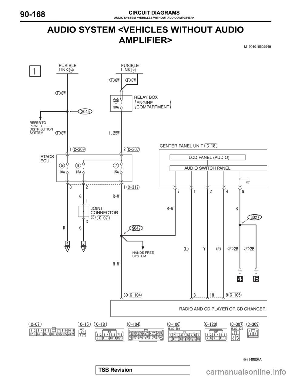
AUDIO SYSTEM
TSB Revision
CIRCUIT DIAGRAMS90-168
AUDIO SYSTEM
M1901015602949
FUSIBLE
LINK34FUSIBLE
LINK36
REFER TO
POWER
DISTRIBUTION
SYSTEM
CENTER PANEL UNIT
ETACS-
ECU
AUDIO SWITCH PANELLCD PANEL (AUDIO)
RADIO AND CD PLAYER OR CD CHANGER RELAY BOX
ENGINE
COMPARTMENT
HANDS FREE
SYSTEM
JOINT
CONNECTOR
(3)
Page 11 of 241
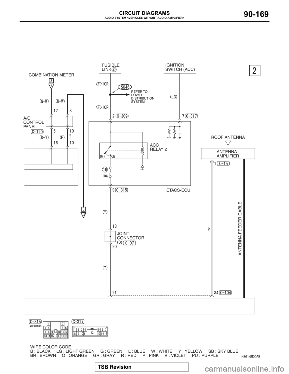
AUDIO SYSTEM
TSB Revision
CIRCUIT DIAGRAMS90-169
FUSIBLE
LINK37
ACC
RELAY 2ROOF ANTENNA
ANTENNA
AMPLIFIER
ANTENNA FEEDER CABLE
ETACS-ECU IGNITION
SWITCH (ACC)
REFER TO
POWER
DISTRIBUTION
SYSTEM
WIRE COLOR CODE
B : BLACK LG : LIGHT GREEN G : GREEN L : BLUE W : WHITE Y : YELLOW SB : SKY BLUE
BR : BROWN O : ORANGE GR : GRAY R : RED P : PINK V : VIOLET PU : PURPLE COMBINATION METER
A/C
CONTROL
PANEL
JOINT
CONNECTOR
(3)
Page 17 of 241
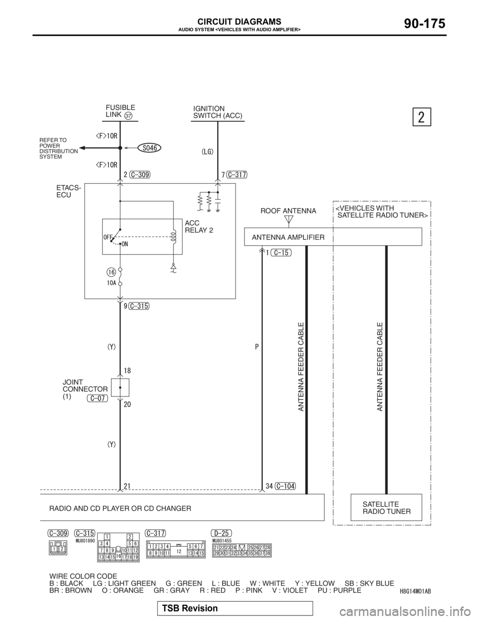
AUDIO SYSTEM
TSB Revision
CIRCUIT DIAGRAMS90-175
ACC
RELAY 2 FUSIBLE
LINK
37
ROOF ANTENNA
ANTENNA AMPLIFIER
ANTENNA FEEDER CABLE ANTENNA FEEDER CABLE
ETACS-
ECU
RADIO AND CD PLAYER OR CD CHANGER
SWITCH (ACC)
SATELLITE
RADIO TUNER
WIRE COLOR CODE
B : BLACK LG : LIGHT GREEN G : GREEN L : BLUE W : WHITE Y : YELLOW SB : SKY BLUE
BR : BROWN O : ORANGE GR : GRAY R : RED P : PINK V : VIOLET PU : PURPLEJOINT
CONNECTOR
(1)
REFER TO
POWER
DISTRIBUTION
SYSTEM
Page 26 of 241
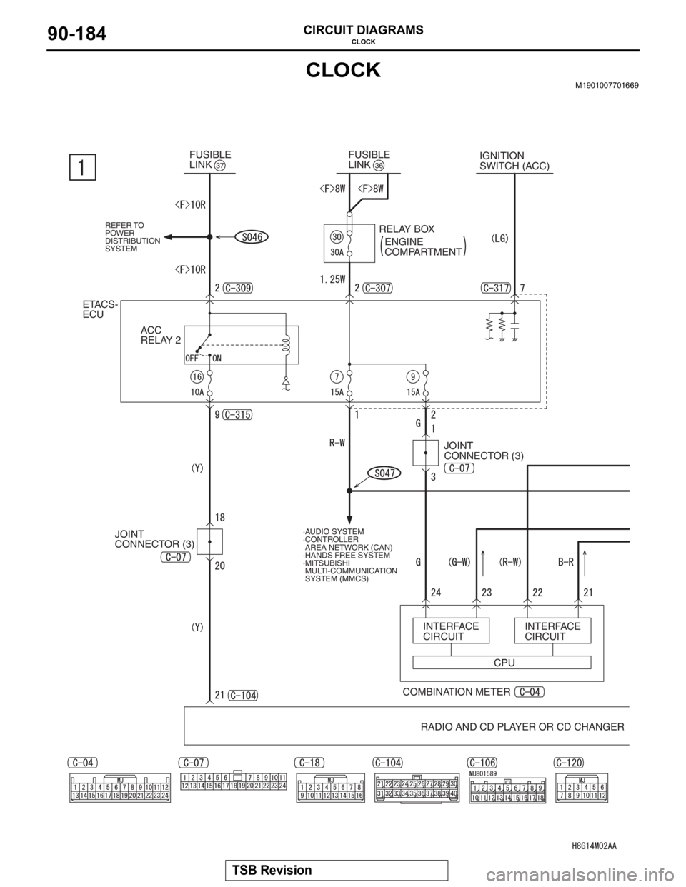
CLOCK
TSB Revision
CIRCUIT DIAGRAMS90-184
CLOCKM1901007701669
ETACS-
ECU
ACC
RELAY 2
37FUSIBLE
LINK36FUSIBLE
LINK
RELAY BOX
ENGINE
COMPARTMENTIGNITION
SWITCH (ACC)
RADIO AND CD PLAYER OR CD CHANGER COMBINATION METERINTERFACE
CIRCUIT
·AUDIO SYSTEM
·CONTROLLER
AREA NETWORK (CAN)
·HANDS FREE SYSTEM
·MITSUBISHI
MULTI-COMMUNICATION
SYSTEM (MMCS)
CPUINTERFACE
CIRCUIT JOINT
CONNECTOR (3)
REFER TO
POWER
DISTRIBUTION
SYSTEM
JOINT
CONNECTOR (3)
Page 27 of 241
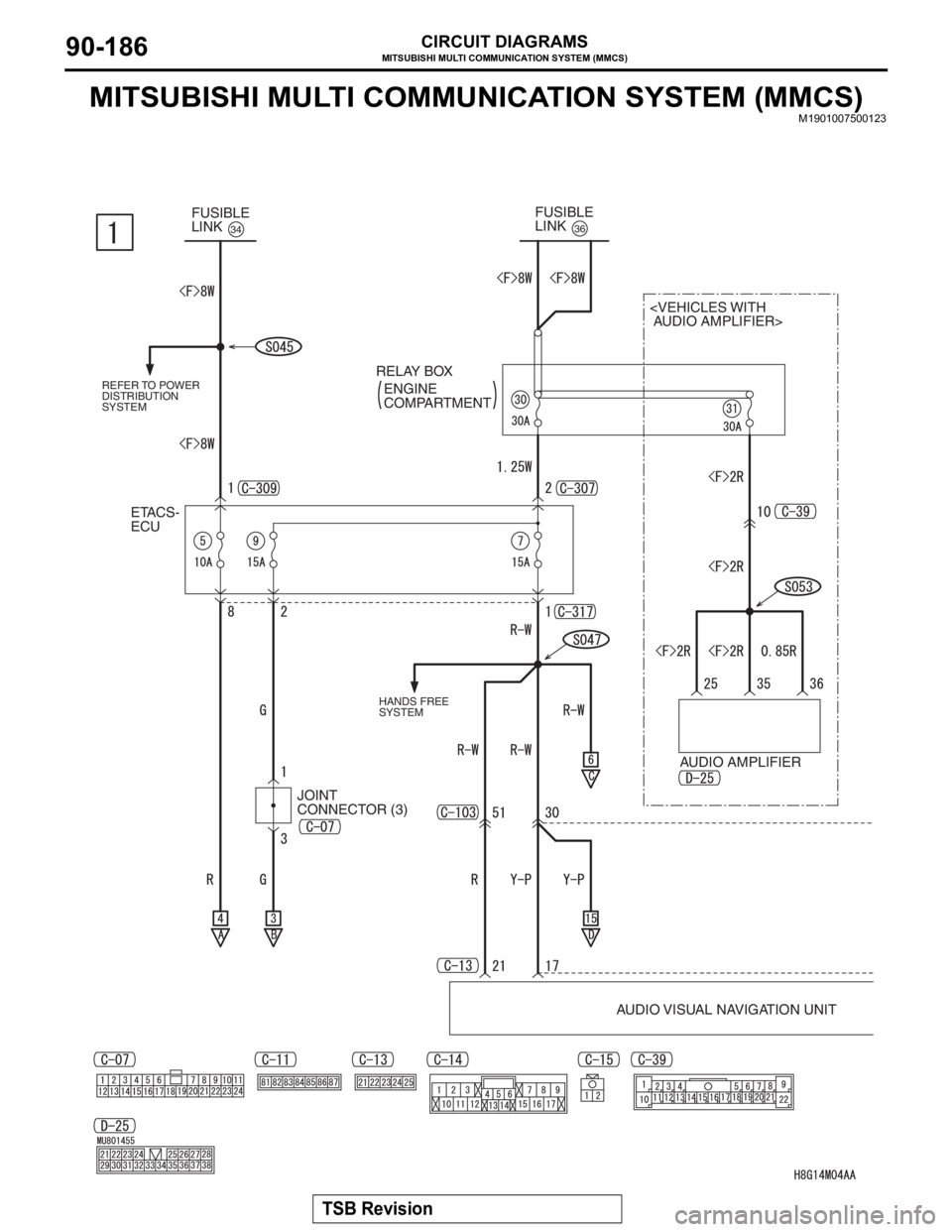
MITSUBISHI MULTI COMMUNICATION SYSTEM (MMCS)
TSB Revision
CIRCUIT DIAGRAMS90-186
MITSUBISHI MULTI COMMUNICATION SYSTEM (MMCS)M1901007500123
FUSIBLE
LINK34
ETACS-
ECUFUSIBLE
LINK
36
AUDIO AMPLIFIER
AUDIO VISUAL NAVIGATION UNIT RELAY BOX
ENGINE
COMPARTMENT
HANDS FREE
SYSTEM REFER TO POWER
DISTRIBUTION
SYSTEM
JOINT
CONNECTOR (3)
Page 28 of 241
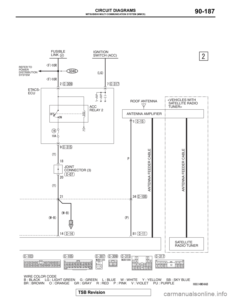
MITSUBISHI MULTI COMMUNICATION SYSTEM (MMCS)
TSB Revision
CIRCUIT DIAGRAMS90-187
ACC
RELAY 2 FUSIBLE
LINK
37
ROOF ANTENNA
ANTENNA AMPLIFIER
ANTENNA FEEDER CABLE ANTENNA FEEDER CABLE
ETACS-
ECU
TUNER> IGNITION
SWITCH (ACC)
SATELLITE
RADIO TUNER
WIRE COLOR CODE
B : BLACK LG : LIGHT GREEN G : GREEN L : BLUE W : WHITE Y : YELLOW SB : SKY BLUE
BR : BROWN O : ORANGE GR : GRAY R : RED P : PINK V : VIOLET PU : PURPLE
REFER TO
POWER
DISTRIBUTION
SYSTEM
JOINT
CONNECTOR (3)
Page 30 of 241
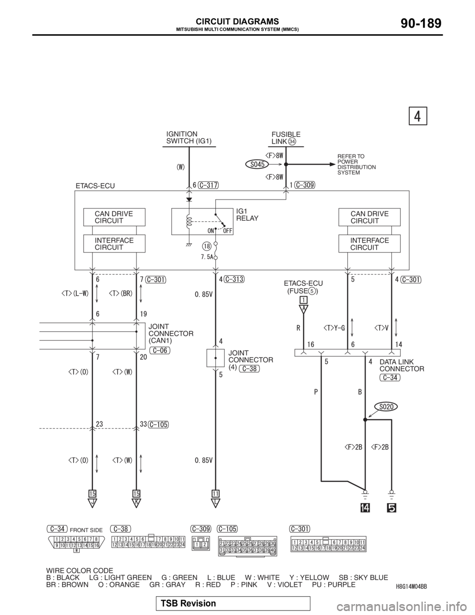
MITSUBISHI MULTI COMMUNICATION SYSTEM (MMCS)
TSB Revision
CIRCUIT DIAGRAMS90-189
INTERFACE
CIRCUITCAN DRIVE
CIRCUIT
DATA LINK
CONNECTOR ETACS-ECU
INTERFACE
CIRCUIT CAN DRIVE
CIRCUIT
ETACS-ECU
(FUSE )
5
WIRE COLOR CODE
B : BLACK LG : LIGHT GREEN G : GREEN L : BLUE W : WHITE Y : YELLOW SB : SKY BLUE
BR : BROWN O : ORANGE GR : GRAY R : RED P : PINK V : VIOLET PU : PURPLEJOINT
CONNECTOR
(CAN1)FUSIBLE
LINK
34IGNITION
SWITCH (IG1)
IG1
RELAY
REFER TO
POWER
DISTRIBUTION
SYSTEM
JOINT
CONNECTOR
(4)
FRONT SIDE
Page 73 of 241
EMISSION CONTROL
ENGINE AND EMISSION CONTROL17-11
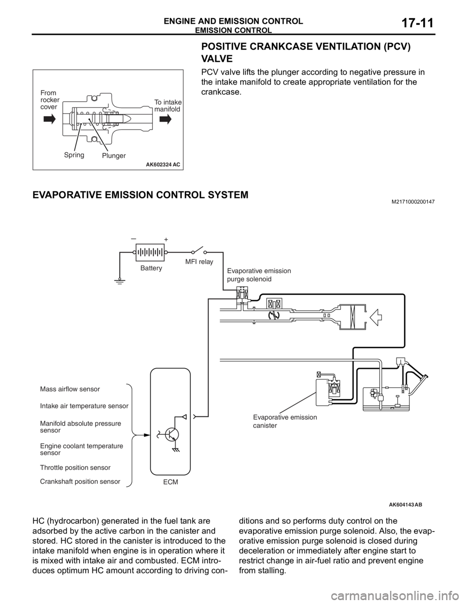
POSITIVE CRANKCASE VENTILATION (PCV)
VA LV E
PCV valve lifts the plunger according to negative pressure in
the intake manifold to create appropriate ventilation for the
crankcase.
EVAPORATIVE EMISSION CONTROL SYSTEMM2171000200147
HC (hydrocarbon) generated in the fuel tank are
adsorbed by the active carbon in the canister and
stored. HC stored in the canister is introduced to the
intake manifold when engine is in operation where it
is mixed with intake air and combusted. ECM intro
-
duces optimum HC amount according to driving con-
ditions and so performs duty control on the
evaporative emission purge solenoid. Also, the evap
-
orative emission purge solenoid is closed during
deceleration or immediately after engine start to
restrict change in air-fuel ratio and prevent engine
from stalling.
AK602324AC
Plunger
From
rocker
coverTo intake
manifold
Spring
AK604143
Evaporative emission
purge solenoid
Mass airflow sensor
ECM Intake air temperature sensor
Manifold absolute pressure
sensor
Engine coolant temperature
sensor
Throttle position sensor
Crankshaft position sensorEvaporative emission
canister
AB
MFI relay
Battery
Page 74 of 241
EMISSION CONTROL
ENGINE AND EMISSION CONTROL17-12
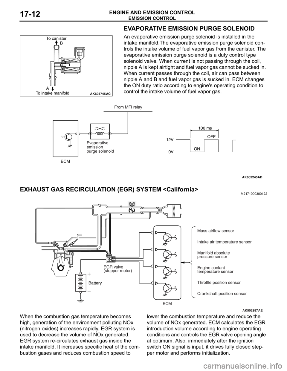
EVAPORATIVE EMISSION PURGE SOLENOID
An evaporative emission purge solenoid is installed in the
intake manifold.The evaporative emission purge solenoid con
-
trols the intake volume of fuel vapor gas from the canister. The
evaporative emission purge solenoid is a duty control type
solenoid valve. When current is not passing through the coil,
nipple A is kept airtight and fuel vapor gas cannot be sucked in.
When current passes through the coil, air can pass between
nipple A and B and fuel vapor gas is sucked in. ECM changes
the ON duty ratio according to engine's operating condition to
control the intake volume of fuel vapor gas.
EXHAUST GAS RECIRCULATION (EGR) SYSTEM
When the combustion gas temperature becomes
high, generation of the environment polluting NOx
(nitrogen oxides) increases rapidly. EGR system is
used to decrease the volume of NOx generated.
EGR system re-circulates exhaust gas inside the
intake manifold. It increases specific heat of the com
-
bustion gases and reduces combustion speed to lower the combustion temperature and reduce the
volume of NOx generated. ECM calculates the EGR
introduction volume according to engine operating
conditions and controls the EGR valve opening angle
at optimum. Also, immediately after the ignition
switch ON signal is input, it drives fully closed step
-
per motor and performs initialization.
AK604745AC
B To canister
To intake manifoldA
AK602245AD
12V
ONOFF
0V100 ms
Evaporative
emission
purge solenoidFrom MFI relay
ECM
AK502987AE
ECMMass airflow sensor
Intake air temperature sensor
Manifold absolute
pressure sensor
Engine coolant
temperature sensor
Throttle position sensor
Crankshaft position sensor BatteryEGR valve
(stepper motor)
Page 75 of 241
EMISSION CONTROL
ENGINE AND EMISSION CONTROL17-13
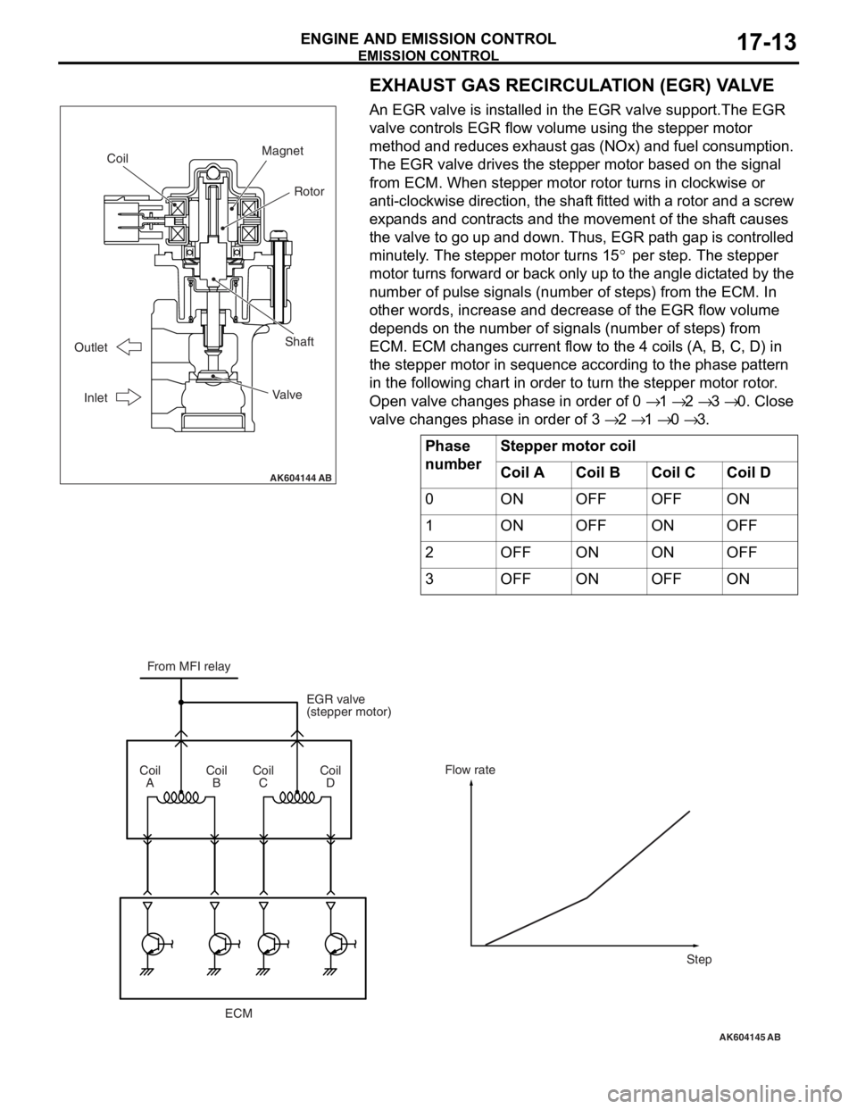
EXHAUST GAS RECIRCULATION (EGR) VALVE
An EGR valve is installed in the EGR valve support.The EGR
valve controls EGR flow volume using the stepper motor
method and reduces exhaust gas (NOx) and fuel consumption.
The EGR valve drives the stepper motor based on the signal
from ECM. When stepper motor rotor turns in clockwise or
anti-clockwise direction, the shaft fitted with a rotor and a screw
expands and contracts and the movement of the shaft causes
the valve to go up and down. Thus, EGR path gap is controlled
minutely. The stepper motor turns 15
° per step. The stepper
motor turns forward or back only up to the angle dictated by the
number of pulse signals (number of steps) from the ECM. In
other words, increase and decrease of the EGR flow volume
depends on the number of signals (number of steps) from
ECM. ECM changes current flow to the 4 coils (A, B, C, D) in
the stepper motor in sequence according to the phase pattern
in the following chart in order to turn the stepper motor rotor.
Open valve changes phase in order of 0
→ 1 → 2 → 3 → 0. Close
valve changes phase in order of 3
→ 2 → 1 → 0 → 3.
Phase
numberStepper motor coil
Coil ACoil BCoil CCoil D
0ONOFFOFFON
1ONOFFONOFF
2OFFONONOFF
3OFFONOFFON
AK604144
Coil
Shaft
Valve Outlet
Inlet
Rotor
Magnet
AB
AK604145
From MFI relay
EGR valve
(stepper motor)
ECM Coil
ACoil
BCoil
CCoil
DFlow rate
Step
AB