steering MITSUBISHI LANCER EVOLUTION X 2008 Workshop Manual
[x] Cancel search | Manufacturer: MITSUBISHI, Model Year: 2008, Model line: LANCER EVOLUTION X, Model: MITSUBISHI LANCER EVOLUTION X 2008Pages: 241, PDF Size: 8.26 MB
Page 2 of 241
COLUMN SWITCH
CHASSIS ELECTRICAL54A-21
COLUMN SWITCH
GENERAL INFORMATIONM2546100200058
Column switch has a function to ensure the driver's
safety during frontal collision of vehicle..
Function
If the column switch is moved to the front of the vehi-
cle and hit on the instrument panel or meter bezel by
the frontal collision of vehicle, the steering wheel is
moved to the front of the vehicle because the right
and left levers fall down, ensuring the driver's safety.
In addition, the column switch secures the rigidity
that the levers do not fall down by the normal opera
-
tion, however, it cannot be reused after the deforma-
tion.
RADIO AND CD PLAYER
GENERAL INFORMATIONM2544900200218
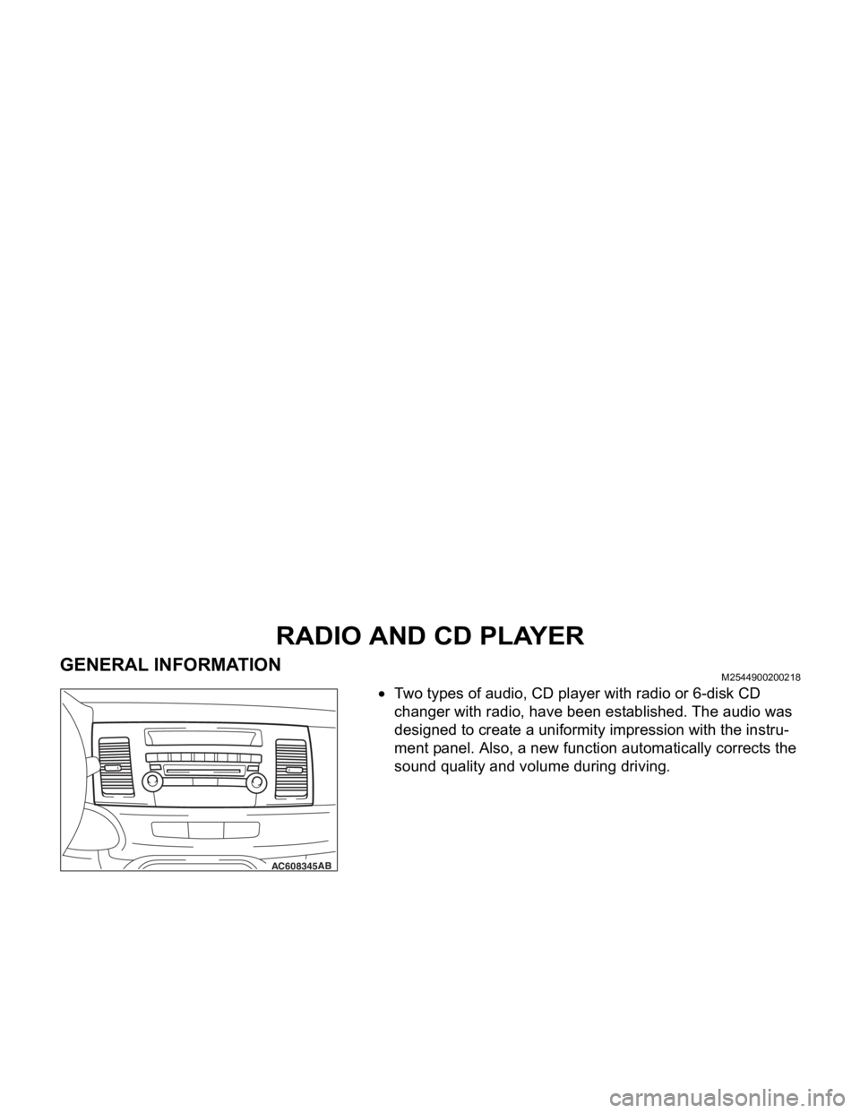
•Two types of audio, CD player with radio or 6-disk CD
changer with radio, have been established. The audio was
designed to create a uniformity impression with the instru
-
ment panel. Also, a new function automatically corrects the
sound quality and volume during driving.
AC603959AB
Collision load Collision load
Column switch Column switch Front of vehicle
AC608345AB
Page 3 of 241
RADIO AND CD PLAYER
CHASSIS ELECTRICAL54A-22
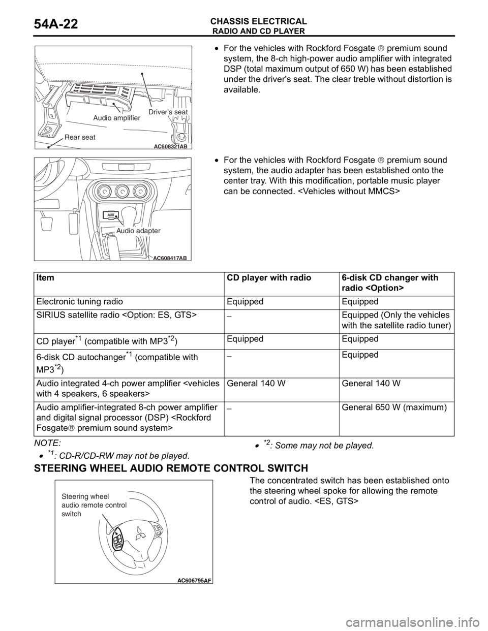
•For the vehicles with Rockford Fosgate ® premium sound
system, the 8-ch high-power audio amplifier with integrated
DSP (total maximum output of 650 W) has been established
under the driver's seat. The clear treble without distortion is
available.
•For the vehicles with Rockford Fosgate ® premium sound
system, the audio adapter has been established onto the
center tray. With this modification, portable music player
can be connected.
NOTE: .
•*1: CD-R/CD-RW may not be played.
•*2: Some may not be played.
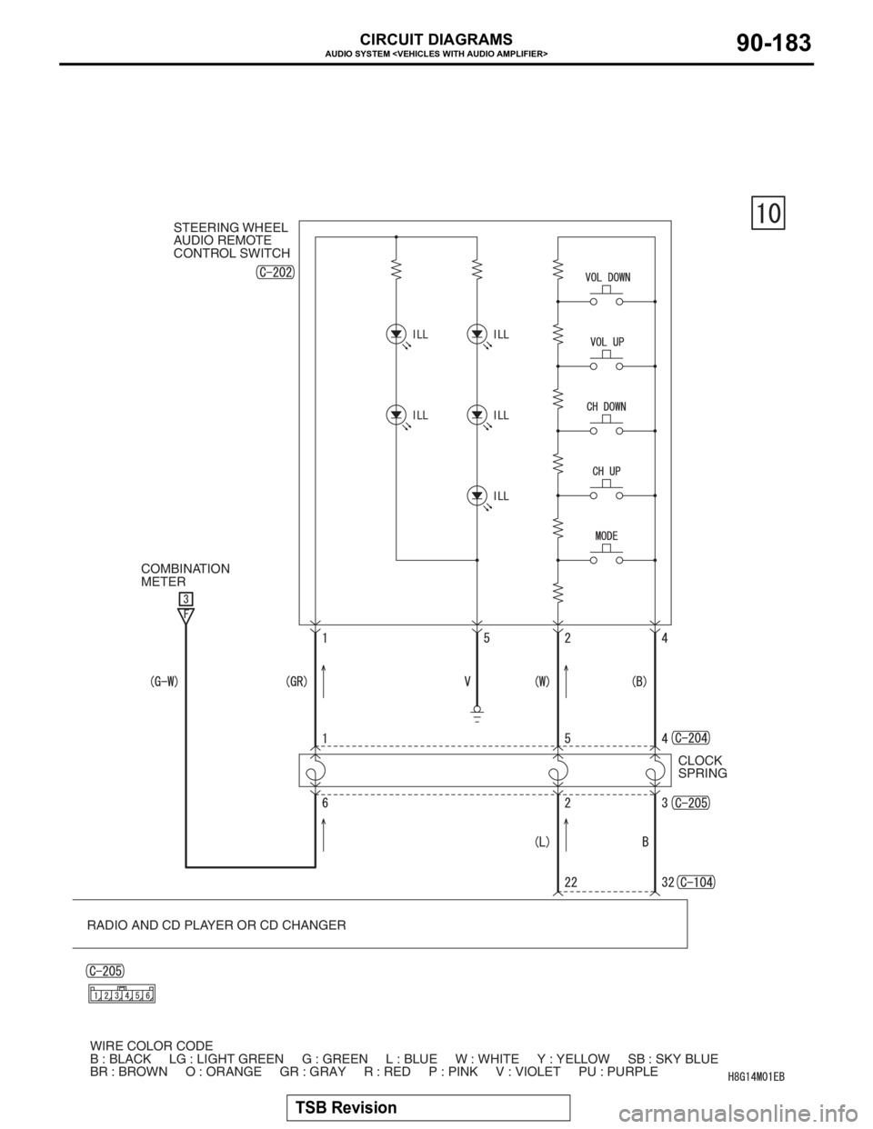
STEERING WHEEL AUDIO REMOTE CONTROL SWITCH
The concentrated switch has been established onto
the steering wheel spoke for allowing the remote
control of audio.
AC608321AB
Driver's seatAudio amplifier
Rear seat
AC608417
AB
Audio adapter
ItemCD player with radio6-disk CD changer with
radio
Page 4 of 241

RADIO AND CD PLAYER
CHASSIS ELECTRICAL54A-23
AUDIO OPERATION TONE ALARM
To prevent an audio operational error, the audio
operation tone alarm confirms the audio operation
which sounds a tone alarm in the combination meter
when the audio is operated. The details are as
described in the following table:
Usage categoryConfirmation tone alarm sounding condition (with conditions below, tone alarm
sounds for 0.08 seconds)
Radio usePress and hold "1", "2", "3", "4", "5" or "6" button.
Press and hold "SCAN" button.
CD usePress and hold the "LOAD" button.
Press and hold the "DISC" button.
Press and hold the "RPT" button.
Press and hold the "RDM" button.
Press and hold the CD eject button
Audio adjustmentWith "BASS", "MID", "TREBLE", "BALANCE", or "FADER" selected, adjust the
adjustment level to zero.
Select "NORMAL" of "SOUND FIELD".
Select "NORMAL" of "MUSIC TYPE".
OthersPress and hold the "TUNE" knob.
Press and hold the "MODE" switch of steering remote control switch.
Page 9 of 241
MITSUBISHI MULTI COMMUNICATION SYSTEM (MMCS)
CHASSIS ELECTRICAL54A-28
Navigation function
The storage of very large map data is now possible,
and the following contents have been adopted.
•Map type navigation
•NAVTEQ map database
•Map data stored in hard disc drive
•U.S. English, French, and Spanish are available
to select.
Audio and visual function
The following functions are in addition to the naviga-
tion function:
•Music server function
•DVD drive unit
•FM/AM radio
•MP3/WMA playback function
•Control by steering wheel audio remote comtrol
switch
•Integrated 4-ch power amplifier (MAX: 180 W)
•Correspond to Rockford Fosgate® premium
sound system
•Output of DVD video 5.1 channel data
•Connect with satellite radio tuner
Other function
The following functions are in addition to the naviga-
tion, audio and visual function:
•Clock display
•Connect with hands free unit
•A/C information display
•Outside temperature display
•Trip information display (Average fuel consump-
tion etc.)
•Function customize
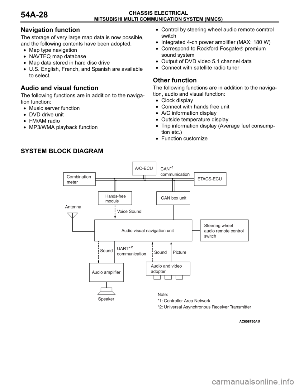
SYSTEM BLOCK DIAGRAM
AC505476
AC608750 ZC3050180000
Audio and video
adopter Antenna
Steering wheel
audio remote control
switch
Speaker
*1: Controller Area Network Note:
*2: Universal Asynchronous Receiver Transmitter UART
communicationn
Sound Sound Voice Sound
Picture
Audio amplifierCAN box unitETACS-ECU Combination
meter
Audio visual navigation unitA/C-ECU
Hands-free
module
CAN
communication
AB
Page 14 of 241
AUDIO SYSTEM
TSB Revision
CIRCUIT DIAGRAMS90-172
AUDIO SYSTEM
RADIO AND CD PLAYER
OR CD CHANGER CLOCK
SPRING STEERING WHEEL
AUDIO REMOTE
CONTROL SWITCH
COMBINATION
METER
WIRE COLOR CODE
B : BLACK LG : LIGHT GREEN G : GREEN L : BLUE W : WHITE Y : YELLOW SB : SKY BLUE
BR : BROWN O : ORANGE GR : GRAY R : RED P : PINK V : VIOLET PU : PURPLE
Page 25 of 241
AUDIO SYSTEM
TSB Revision
CIRCUIT DIAGRAMS90-183
RADIO AND CD PLAYER OR CD CHANGER CLOCK
SPRING STEERING WHEEL
AUDIO REMOTE
CONTROL SWITCH
COMBINATION
METER
WIRE COLOR CODE
B : BLACK LG : LIGHT GREEN G : GREEN L : BLUE W : WHITE Y : YELLOW SB : SKY BLUE
BR : BROWN O : ORANGE GR : GRAY R : RED P : PINK V : VIOLET PU : PURPLE
Page 97 of 241
GENERAL DESCRIPTION
MULTIPORT FUEL SYSTEM (MFI)13A-3
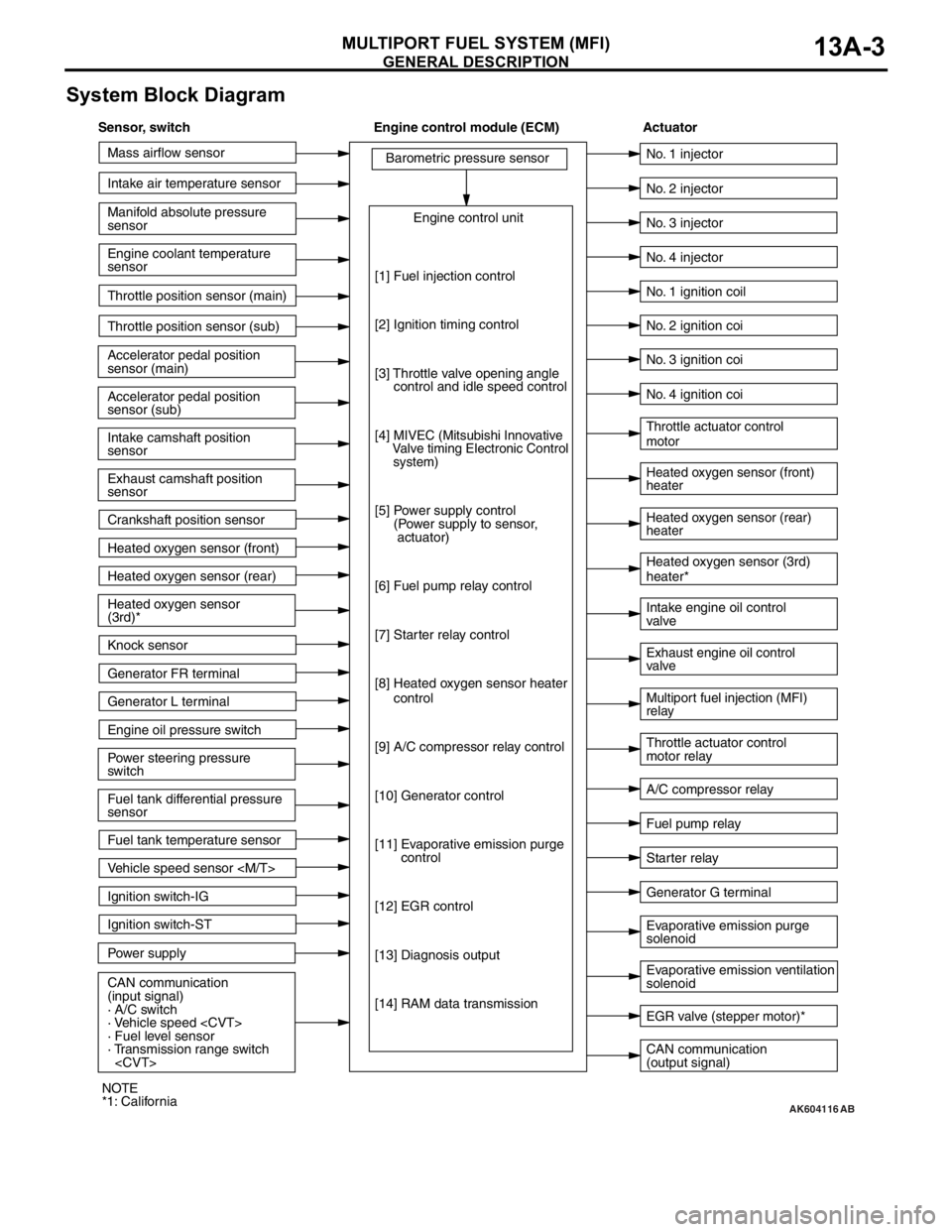
System Block Diagram
AK604116
Mass airflow sensor
Intake air temperature sensor
Intake camshaft position
sensor
Exhaust camshaft position
sensor
Crankshaft position sensor Throttle position sensor (main)
Throttle position sensor (sub)
Accelerator pedal position
sensor (sub) Accelerator pedal position
sensor (main) Engine coolant temperature
sensor Manifold absolute pressure
sensor
Heated oxygen sensor (front)
Heated oxygen sensor (rear)
Power steering pressure
switch Engine oil pressure switch Generator L terminal
Ignition switch-ST
Power supply Ignition switch-IG
CAN communication
(input signal)
· A/C switch
· Vehicle speed
· Fuel level sensor
· Transmission range switch
sensor Heated oxygen sensor
(3rd)*
Knock sensor
Generator FR terminal
Fuel tank temperature sensor
Vehicle speed sensor
[1] Fuel injection control
[2] Ignition timing control
[3] Throttle valve opening angle
control and idle speed control
[4]
MIVEC (Mitsubishi Innovative
Valve timing Electronic Control
system)
[5] Power supply control
(Power supply to sensor,
actuator)
[6] Fuel pump relay control
[7] Starter relay control
[8] Heated oxygen sensor heater
control
[9] A/C compressor relay control
[10] Generator control
[11] Evaporative emission purge
control
[12] EGR control
[13] Diagnosis output
[14] RAM data transmission
CAN communication
(output signal) Intake engine oil control
valve
A/C compressor relay No. 2 injector
No. 3 injector
No. 4 injector
Heated oxygen sensor (front)
heater
Heated oxygen sensor (rear)
heater Throttle actuator control
motor
Throttle actuator control
motor relay No. 1 injector
No. 1 ignition coil
No. 2 ignition coi
No. 3 ignition coi
No. 4 ignition coi
Fuel pump relay
Generator G terminal Heated oxygen sensor (3rd)
heater*
Multiport fuel injection (MFI)
relay Exhaust engine oil control
valve
Evaporative emission ventilation
solenoid Evaporative emission purge
solenoid
EGR valve (stepper motor)*
Starter relay
AB
Sensor, switch Engine control module (ECM) Actuator
NOTE
*1: California
Page 98 of 241
GENERAL DESCRIPTION
MULTIPORT FUEL SYSTEM (MFI)13A-4
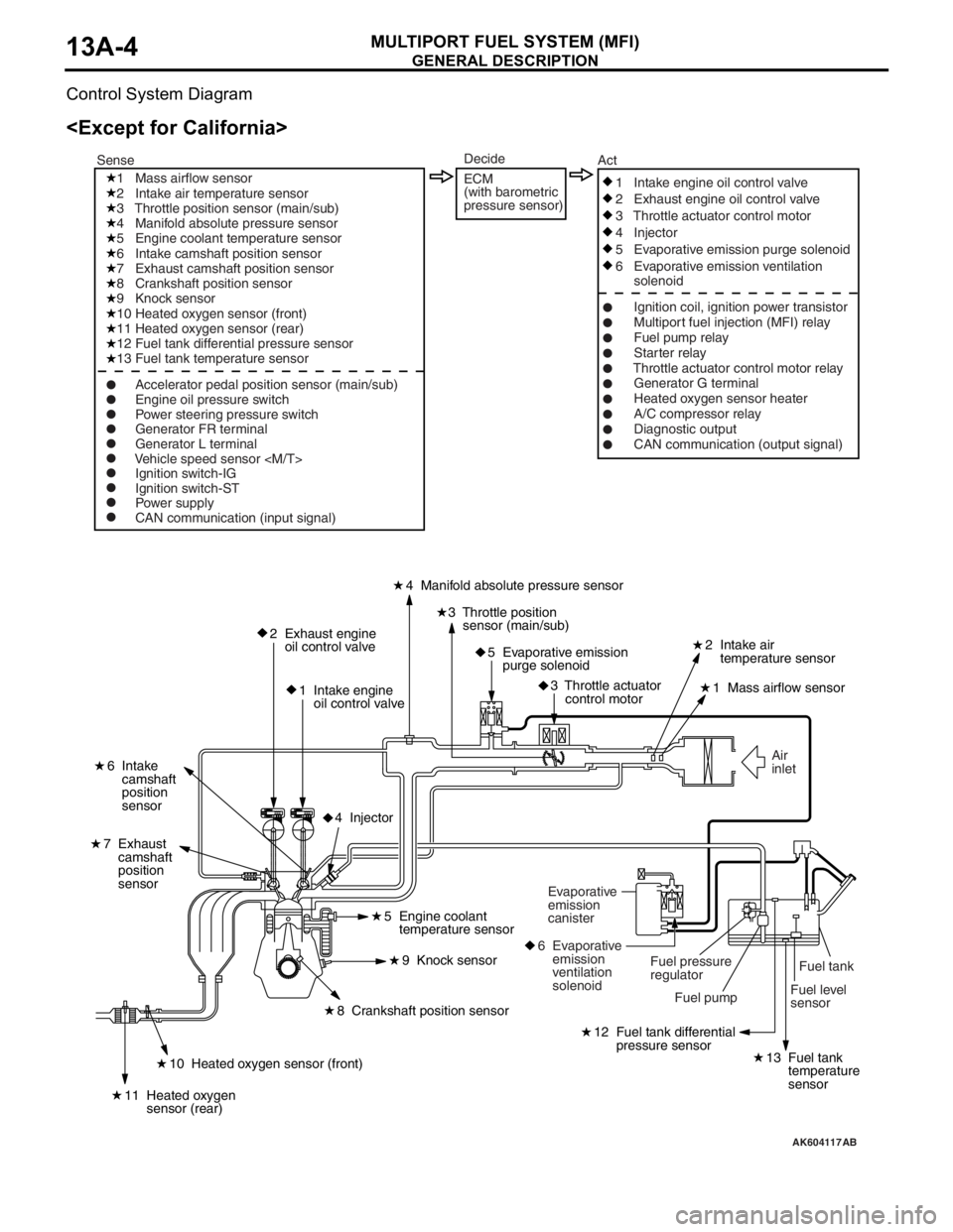
Control System Diagram
AK604117
Fuel level
sensorFuel tank Air
inlet
2 Exhaust engine
oil control valve
1 Intake engine
oil control valve4 Manifold absolute pressure sensor
2 Intake air
temperature sensor
1 Mass airflow sensor
6 Intake
camshaft
position
sensor
7 Exhaust
camshaft
position
sensor
3 Throttle position
sensor (main/sub)
5 Evaporative emission
purge solenoid
3 Throttle actuator
control motor
12 Fuel tank differential
pressure sensor
13 Fuel tank
temperature
sensor10 Heated oxygen sensor (front)
11 Heated oxygen
sensor (rear)
8 Crankshaft position sensor5 Engine coolant
temperature sensor
9 Knock sensor
4 Injector
Fuel pump Fuel pressure
regulator Evaporative
emission
canister
6 Evaporative
emission
ventilation
solenoid
1 Mass airflow sensor
2 Intake air temperature sensor
3 Throttle position sensor (main/sub)
4 Manifold absolute pressure sensor
5 Engine coolant temperature sensor
6 Intake camshaft position sensor
7 Exhaust camshaft position sensor
8 Crankshaft position sensor
9 Knock sensor
10 Heated oxygen sensor (front)
11 Heated oxygen sensor (rear)
12 Fuel tank differential pressure sensor
13 Fuel tank temperature sensor
Ignition switch-IG
Ignition switch-ST
Power supply
CAN communication (input signal)1 Intake engine oil control valve
2 Exhaust engine oil control valve
3 Throttle actuator control motor
4 Injector
5 Evaporative emission purge solenoid
6 Evaporative emission ventilation
solenoid
Ignition coil, ignition power transistor
Multiport fuel injection (MFI) relay
Fuel pump relay
Starter relay
Throttle actuator control motor relay
Generator G terminal
Heated oxygen sensor heater
A/C compressor relay
Diagnostic output
CAN communication (output signal) SenseAct
Engine oil pressure switch
Power steering pressure switch
Generator FR terminal
Generator L terminal
Vehicle speed sensor
Decide
ECM
(with barometric
pressure sensor)
AB
Page 99 of 241
GENERAL DESCRIPTION
MULTIPORT FUEL SYSTEM (MFI)13A-5
AK604118
Fuel tank
Fuel level
sensor Air
inlet
2 Exhaust engine
oil control valve
1 Intake engine
oil control valve4 Manifold absolute pressure sensor
2 Intake air
temperature sensor
1 Mass airflow sensor
6 Intake
camshaft
position
sensor
7 Exhaust
camshaft
position
sensor
3 Throttle position
sensor (main/sub)
5 Evaporative emission
purge solenoid
3 Throttle actuator
control motor
12 Fuel tank differential
pressure sensor
13 Fuel tank
temperature
sensor11 Heated oxygen sensor (rear)
10 Heated
oxygen
sensor
(front)
12 Heated oxygen sensor (3rd)
8 Crankshaft position sensor5 Engine
coolant
temperature
sensor
9 Knock sensor
4 Injector
Fuel pump Fuel pressure
regulator Evaporative
emission
canister
6 Evaporative
emission
ventilation
solenoid
7 EGR valve
(stepper motor)
1 Mass airflow sensor
2 Intake air temperature sensor
3 Throttle position sensor (main/sub)
4 Manifold absolute pressure sensor
5 Engine coolant temperature sensor
6 Intake camshaft position sensor
7 Exhaust camshaft position sensor
8 Crankshaft position sensor
9 Knock sensor
10 Heated oxygen sensor (front)
11 Heated oxygen sensor (rear)
12 Heated oxygen sensor (3rd)
13 Fuel tank differential pressure sensor
14 Fuel tank temperature sensor
Ignition switch-IG
Ignition switch-ST
Power supply
CAN communication (input signal)1 Intake engine oil control valve
2 Exhaust engine oil control valve
3 Throttle actuator control motor
4 Injector
5 Evaporative emission purge solenoid
6 Evaporative emission ventilation
solenoid
7 EGR valve (stepper motor)
Ignition coil, ignition power transistor
Multiport fuel injection (MFI) relay
Fuel pump relay
Starter relay
Throttle actuator control motor relay
Generator G terminal
Heated oxygen sensor heater
A/C compressor relay
Diagnostic output
CAN communication (output signal) SenseAct
Engine oil pressure switch
Power steering pressure switch
Generator FR terminal
Generator L terminal
Vehicle speed sensor
Decide
ECM
(with barometric
pressure sensor)
AB
Page 112 of 241
SENSOR
MULTIPORT FUEL SYSTEM (MFI)13A-19
.
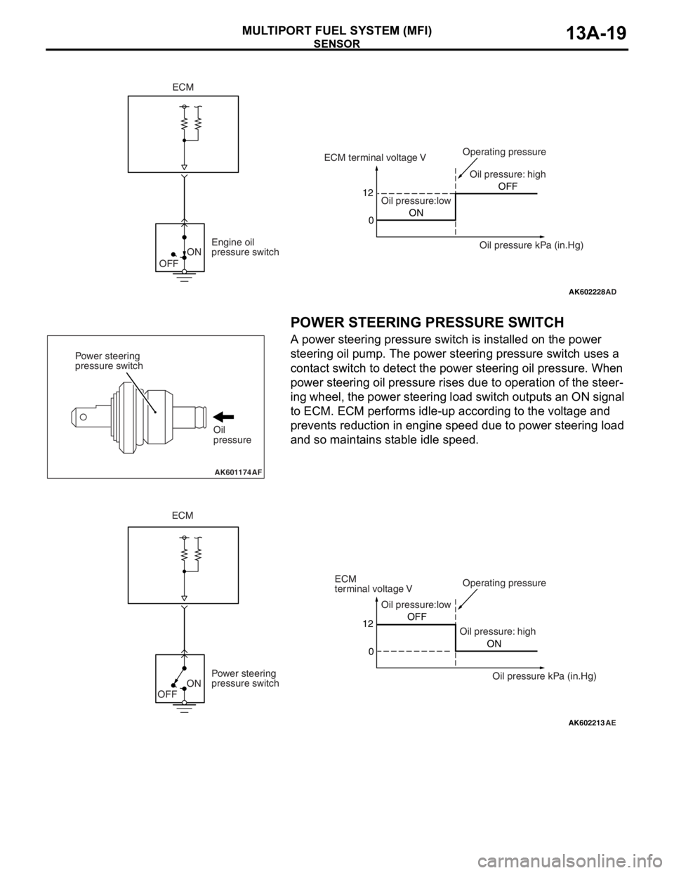
POWER STEERING PRESSURE SWITCH
A power steering pressure switch is installed on the power
steering oil pump. The power steering pressure switch uses a
contact switch to detect the power steering oil pressure. When
power steering oil pressure rises due to operation of the steer
-
ing wheel, the power steering load switch outputs an ON signal
to ECM. ECM performs idle-up according to the voltage and
prevents reduction in engine speed due to power steering load
and so maintains stable idle speed.
.
AK602228
ON
OFF
AD
12
0ONOFF ECM terminal voltage V
Oil pressure:lowOil pressure: high Operating pressure
Oil pressure kPa (in.Hg) Engine oil
pressure switch
ECM
AK601174AF
Power steering
pressure switch
Oil
pressure
AK602213
ON
OFF
AE
Oil pressure:low
Oil pressure: highOperating pressure
Power steering
pressure switch12
0OFF
ON
ECM
ECM
terminal voltage V
Oil pressure kPa (in.Hg)