wheel MITSUBISHI LANCER IX 2006 User Guide
[x] Cancel search | Manufacturer: MITSUBISHI, Model Year: 2006, Model line: LANCER IX, Model: MITSUBISHI LANCER IX 2006Pages: 800, PDF Size: 45.03 MB
Page 145 of 800
AC100136
MB990685MB990326
AB
FRONT AXLE HUB ASSEMBL Y
FRONT AXLE26-13
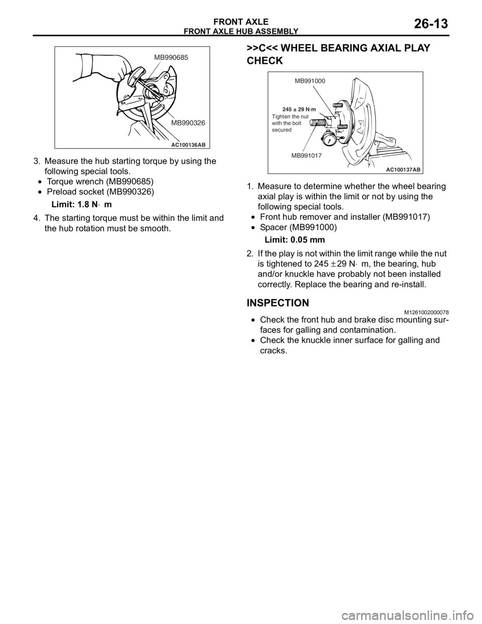
3.Measure the hub st a r ting torque b y using the
fo llowing special to ols.
•To rque wren ch (MB99068 5)
•Preload socket (MB9 90326 )
Limit: 1.8 N⋅m
4.Th e st arting torq ue must b e within the limit an d
th e hub rot a tion must be smoo th.
>>C<< WH EEL BEARING AXIAL PLA Y
CHECK
AC100137
MB991000
MB991017
245 ± 29 N·m AB
Tighten the nut
with the bolt
secured
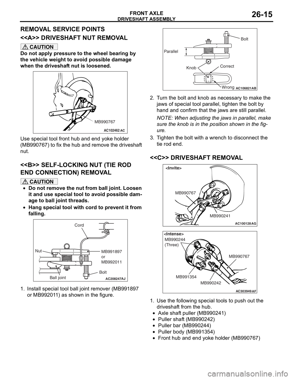
1.
Measure to d e termine whe t her th e wheel bearing
a x ial pla y is with in the limit o r not by using t he
fo llowing special to ols.
•Front hub re mover and inst a ller (MB9910 17)
•Sp a c er (MB9910 00)
Limit: 0.05 mm
2. If the play is not wit h in the limit rang e while the nut
is tighten ed to 2 45
± 29 N⋅m, the bearing, hu b
a
nd/or knuckle
have
proba
bly not be en in st alled
correctly
. Replace
the be
aring and re -inst a ll.
INSPECTION
M12610020 0007 8
•Check the fro n t hu b and brake disc mo untin g sur-
faces for gallin g and cont amination.
•Check the knu c kle in ner surface for ga lling an d
crac
ks .
Page 147 of 800
Page 148 of 800
AC102551AC
Drive shaft
DRIVESHAFT ASSEMBL Y
FRONT AXLE26-16
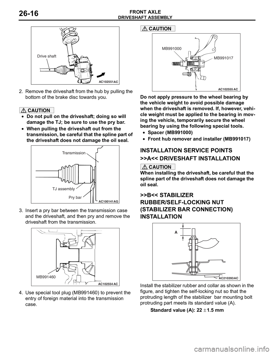
2.Remove th e dr ivesh a f t from th e h ub b y p u lling the
bo ttom of the brake disc toward s you.
CAUTION
•Do not pull on the driveshaft; doing so will
damage the TJ; be sure to use the pry bar.
•
AC100141
Transmission
TJ assembly Pry bar
AG
When pulling the driveshaft out from the
transmission, be careful that the spline part of
the driveshaft does not damage the oil seal.
3. Insert a pry bar between the transmission case and the driveshaft, and then pry and remove the
driveshaft from the transmission.
AC102554
MB991460
AC
4. Use special tool plug (MB991460) to prevent the
entry of foreign material into the transmission
case.
AC102555 AC
MB991017
MB991000
CAUTION
Do not apply pressure to the wheel bearing by
the vehicle weight to avoid possible damage
when the driveshaft is removed. If, however, vehi
-
cle weight must be applied to the bearing in mov-
ing the vehicle, temporarily secure the wheel
bearing by using the following special tools.
•Spacer (MB991000)
•Front hub remover and installer (MB991017)
INSTALLATION SERVICE POINTS
>>A<< DRIVESHAFT INSTALLATION
CAUTION
When installing the driveshaft, be careful that the
spline part of the driveshaft does not damage the
oil seal.
>>B<< STABILIZER
RUBBER/SELF-LOCKING NUT
(STABILIZER BAR CONNECTION)
INSTALLATION
AC210393
AC
A
Install the stabilizer rubber and collar as shown in the
figure, and tighten the self-locking nut so that the
protruding length of the stabilizer bar mounting bolt
protruding part meets its standard value (A).
Standard value (A): 22 ± 1.5 mm
Page 149 of 800
DRIVESHAFT ASSEMBLY
FRONT AXLE26-17
>>C<< WASHER/DRIVESHAFT NUT
INSTALLATION
AC102465AD
MB990767
Washer
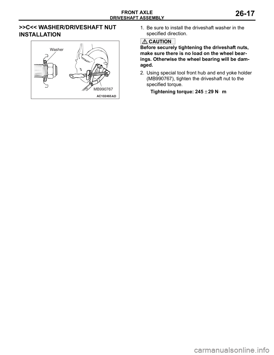
1.
Be sure t o inst a ll t he driveshaf t washe r in th e
specifie d dire ctio n.
CAUTION
Before securely tightening the driveshaft nuts,
make sure there is no load on the wheel bear
-
ings. Otherwise the wheel bearing will be dam-
aged.
2. Using special tool front hub and end yoke holder (MB990767), tighten the driveshaft nut to the
specified torque.
Tightening torque: 245 ± 29 N⋅m
Page 157 of 800
27-1
GROUP 27
REAR AXLE
CONTENTS
GENERAL INFORMATION . . . . . . . .27-2
SERVICE SPECIFICATIONS . . . . . . .27-2
SEALANT . . . . . . . . . . . . . . . . . . . . . .27-2
SPECIAL TOOLS . . . . . . . . . . . . . . . .27-3
ON-VEHICLE SERVICE . . . . . . . . . . .27-4
WHEEL BEARING AXIAL PLAY CHECK . . 27-4
REAR HUB ROTARY-SLIDING
RESISTANCE CHECK . . . . . . . . . . . . . . . . 27-4
HUB BOLT REPLACEMENT . . . . . . . . . . . . 27-4
REAR AXLE HUB ASSEMBLY . . . . .27-5
REMOVAL AND INSTALLATION . . . . . . . . 27-5
INSPECTION. . . . . . . . . . . . . . . . . . . . . . . . 27-6
Page 158 of 800
GENERAL INFORMATION
REAR AXLE27-2
GENERAL INFORMATION
M1271000100304
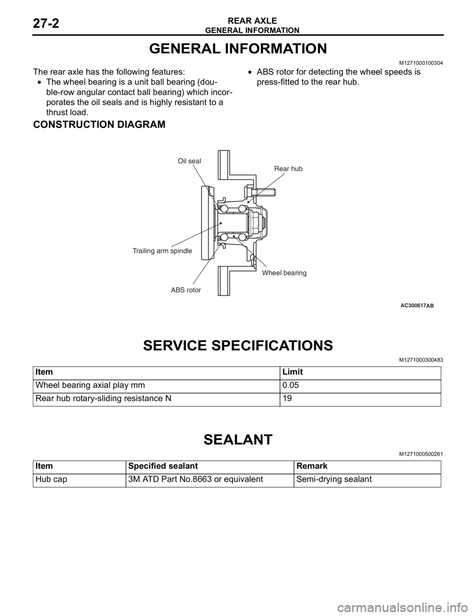
The rear axle has the following features:
•The wheel bearing is a unit ball bearing (dou-
ble-row angular contact ball bearing) which incor-
porates the oil seals and is highly resistant to a
thrust load.
•ABS rotor for detecting the wheel speeds is
press-fitted to the rear hub.
CONSTRUCTION DIAGRAM
AC300617AB
Rear hub
Oil seal
Wheel bearing
ABS rotor
Trailing arm spindle
SER
V ICE SPECI F ICA T IONS
M12710003 0048 3
ItemLimit
Wheel bearing axial play mm0.05
Rear hub rotary-sliding resistance N19
SEALANT
M12710005 0026 1
ItemSpecified sealantRemark
Hub cap3M ATD Part No.8663 or equivalentSemi-drying sealant
Page 160 of 800
ON-VEHICLE SERVICE
REAR AXLE27-4
ON-VEHICLE SERVICE
WHEEL BEARING AXIAL PLAY CHECKM1271000900452
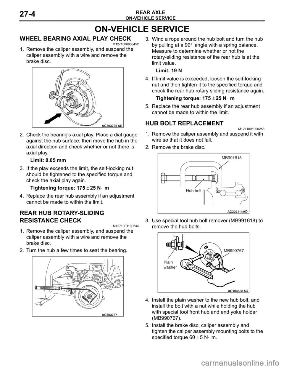
1. Remove the caliper assembly, and suspend the caliper assembly with a wire and remove the
brake disc.
AC303736AB
2.Check the be aring ' s axial play . Place a dial gau ge
ag ainst th e hub su rface; then mo ve t he hu b in the
axial dire ction and check whe t her or not the r e is
axial pla y .
Limit: 0.05 mm
3.If the play e xce eds the limit, the self -lockin g nut
should be tighte ned to the specified torque and
check the axial play again .
Ti ghte n ing torque: 175 ± 25 N⋅m
4.Replace the re ar hub a s sembly if an ad justmen t
cannot be made to within the limit.
REAR HUB ROTA R Y -SLIDING
RESIST
ANCE CHECK
M127100 1 1 0024 4
1.Remove the caliper assembly , a nd suspe nd the
caliper assembly with a wire an d remove t he
bra k e d i sc.
2.T u rn the hu b a few times to seat th e bea ring.
AC303737
3.Wind a rope a r ound the hu b bolt and turn t he hub
b y pullin g at a 90
° angle with a spring balance.
Measure to d
e
termine whe t her or not the
ro
t
a
ry-sliding resist an ce of the rea r hub is at the
limit va
lue.
Limit: 19 N
4.If limit value is exceeded , loo s en the self-locking
n u t and then tighten it to the specified torque and
check the rear hu b rot a ry sliding resist ance again.
Ti ghte n ing torque: 175 ± 25 N⋅m
5.Replace the re ar hub assembly if an a d justmen t
canno t be made to within the limit.
HUB BOLT REPLACEMENTM12710010 0025 8
1.Remove the calip er assembly and suspe nd it with
wire so t hat it does not fa ll.
2.Remove the bra k e d i sc.
AC302114
MB991618
AD
Hub bolt
3.Use spe c ia l too l hub bolt remover (MB99161 8) to
re move the h ub bo lt s.
AC104588
MB990767
Plain
washer
AC
4. In st all the plain wa sher to the n e w hub b o lt, a nd
inst all the bolt with a nu t while hold i ng the hub
wit h spe c ia l too l fron t hub a nd end yoke holder
(MB99076 7).
5.In st all the bra k e d i sc, ca lip er assembly and
tighten th e caliper assembly mount ing bolt s to the
specifie d torqu e 60
± 5 N⋅m.
Page 161 of 800
REAR AXLE HUB ASSEMBLY
REAR AXLE27-5
REAR AXLE HUB ASSEMBLY
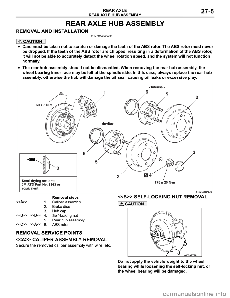
REMOVAL AND INSTALLATIONM1271002000381
CAUTION
•Care must be taken not to scratch or damage the teeth of the ABS rotor. The ABS rotor must never
be dropped. If the teeth of the ABS rotor are chipped, resulting in a deformation of the ABS rotor,
it will not be able to accurately detect the wheel rotation speed, and the system will not function
normally.
•
AC504437
Semi-drying sealant:
3M ATD Part No. 8663 or
equivalent
2
3
5
6
4
N
175 ± 25 N·m
3
AB
1
60 ± 5 N·m
2
56
Removal steps
<>1.Caliper assembly
2.Brake disc
3.Hub cap
<>>>B<<4.Self-locking nut
5.Rear hub assembly
<
The rear hub assembly should not be dismantled. When removing the rear hub assembly, the
wheel bearing inner race may be left at the spindle side. In this case, always replace the rear hub
assembly, otherwise the hub will damage the oil seal, causing oil leaks or excessive play.
REMOVAL SERVICE POINTS
<> CALIPER ASSEMBLY REMOVAL
Secure the removed caliper assembly with wire, etc.
<> SELF-LOCKING NUT REMOVAL
AC303738
CAUTION
Do not apply the vehicle weight to the wheel
bearing while loosening the self-locking nut, or
the wheel bearing will be damaged.
Page 162 of 800
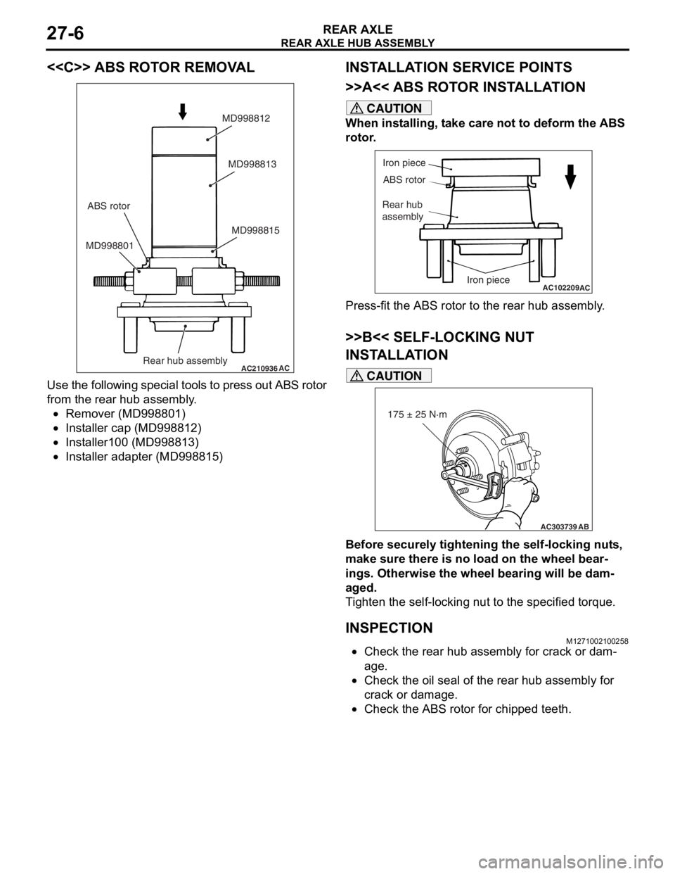
REAR AXLE HUB ASSEMBLY
REAR AXLE27-6
<
AC210936AC
MD998815
MD998801 MD998813
MD998812
Rear hub assembly
ABS rotor
Use
the fo llowing specia l to ols t o press o u t ABS rot o r
from th
e rear h ub assembly .
•Remover (MD99880 1)
•Insta lle r cap (MD9988 12)
•Insta lle r100 (MD9 98813 )
•Insta lle r adapte r (MD998 815)
INSTALLA T ION SER VICE POINTS
>>A<< ABS ROTO R INST ALLA TION
CAUTION
When installing, take care not to deform the ABS
rotor.
AC102209
Iron piece
ABS rotor
Rear hub
assembly
Iron piece
AC
Press-fit the ABS rotor to the rear hub assembly.
>>B<< SELF-LOCKING NUT
INSTALLATION
AC303739
175 ± 25 N·m
AB
CAUTION
Before securely tightening the self-locking nuts,
make sure there is no load on the wheel bear
-
ings. Otherwise the wheel bearing will be dam-
aged.
Tighten the self-locking nut to the specified torque.
INSPECTIONM1271002100258
•Check the rear hub assembly for crack or dam-
age.
•Check the oil seal of the rear hub assembly for
crack or damage.
•Check the ABS rotor for chipped teeth.
Page 163 of 800

31-1
GROUP 31
WHEEL AND TYRE
CONTENTS
GENERAL INFORMATION . . . . . . . .31-2
SERVICE SPECIFICATIONS . . . . . . .31-2
TROUBLESHOOTING . . . . . . . . . . . .31-3
DIAGNOSIS . . . . . . . . . . . . . . . . . . . . . . . . 31-3
WHEEL BALANCE ACCURACY . . . . . . . . 31-4
ON-VEHICLE SERVICE . . . . . . . . . . .31-7
TYRE INFLATION PRESSURE CHECK . . . 31-7
TYRE WEAR CHECK . . . . . . . . . . . . . . . . . 31-7
WHEEL RUNOUT CHECK . . . . . . . . . . . . . 31-7
WHEEL AND TYRE . . . . . . . . . . . . . .31-7
INSTALLATION SERVICE POINT . . . . . . . 31-7