wheel MITSUBISHI LANCER IX 2006 Workshop Manual
[x] Cancel search | Manufacturer: MITSUBISHI, Model Year: 2006, Model line: LANCER IX, Model: MITSUBISHI LANCER IX 2006Pages: 800, PDF Size: 45.03 MB
Page 222 of 800
GENERAL INFORMATION
PARKING BRAKES36-2
GENERAL INFORMATION
M1361000100496
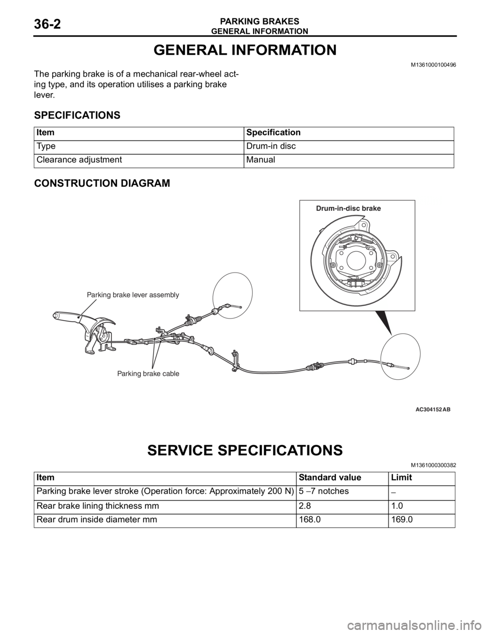
The parking brake is of a mechanical rear-wheel act-
ing type, and its operation utilises a parking brake
lever.
SPECIFICATIONS
ItemSpecification
Ty p eDrum-in disc
Clearance adjustmentManual
CONSTRUCTION DIAGRAM
AC211553
AC104333
AC304152
Parking brake lever assembly
Parking brake cable
AB
Drum-in-disc brake
SERV ICE SPECI F ICA T IONS
M13610003 0038 2
ItemStandard valueLimit
Parking brake lever stroke (Operation force: Approximately 200 N)5 − 7 notches−
Rear brake lining thickness mm2.81.0
Rear drum inside diameter mm168.0169.0
Page 223 of 800
LUBRICANTS
PARKING BRAKES36-3
LUBRICANTS
M1361000400293
ItemSpecified lubricant
Rear brake shoe and backing plate contact surfaceBrake grease SAE J310, NLGI No.1
Rear brake shoe assembly
Rear brake shoe slack adjuster
ON-VEHIC LE SER VI CE
PARKING BRAKE LE VER STROKE
CHECK AND ADJUSTMENT
M13610009 0033 9
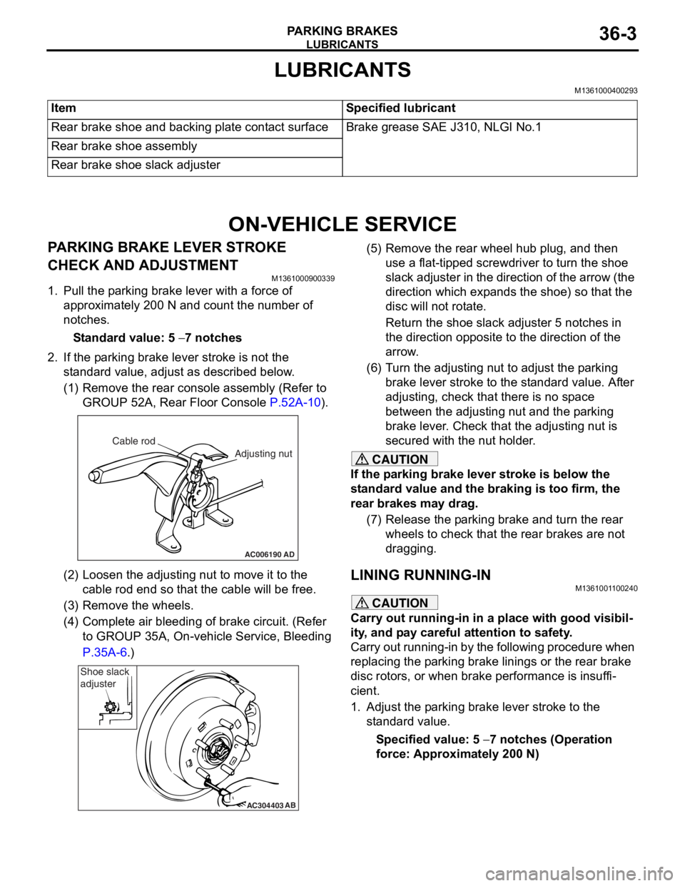
1.Pull the p a rkin g brake le ver wit h a force of
ap proxima t ely 200 N an d co unt the number of
no tche s.
St andard va lue: 5 − 7 notches
2.If the p a rking b r ake leve r stro ke is no t the
st a ndard valu e, adjust as de scribed below .
(1)R emove the rear console a sse mbly (Refer to
GROUP 5 2 A, Rear Floor Console
P.52A-10).
AC006190
Cable rod
Adjusting nut
AD
(2)Loosen th e adjusting nu t to move it to th e
cab l e rod end so tha t the cable will be fre e .
(3)R emove the wheels.
(4)C omplete a i r bleedin g of b r ake circuit. (Re f er
to GROUP 35A, On-ve h icle Service, Blee ding
P.35A-6.)
AC304403AB
Shoe slack
adjuster
(5
) R emove the rear whee l hub plug , and then
use a flat-tipped screwdriver to turn the shoe
slack ad juster in the direction of the arrow (the
dire ctio n which exp a nds the shoe) so that the
disc will no t rot a te.
Return the sh oe slack adjust e r 5 not ches in
the d
i rection opposite t o the d i rection of the
arrow
.
(6) T urn th e adjusting nut to adjust the p a rking
brake le ver stroke to the st anda rd value. Af ter
adjusting, check that there is n o sp ace
between the a d justing nut an d the p a rking
brake le ver . Che ck that th e adjusting nut is
secured with the nut ho lder .
CAUTION
If the parking brake lever stroke is below the
standard value and the braking is too firm, the
rear brakes may drag.
(7) Release the parking brake and turn the rear wheels to check that t he rear brakes are not
dragging.
LINING RUNNING-INM1361001100240
CAUTION
Carry out running-in in a place with good visibil-
ity, and pay careful attention to safety.
Carry out running-in by the following procedure when
replacing the parking brake linings or the rear brake
disc rotors, or when brake performance is insuffi
-
cient.
1. Adjust the parking brake lever stroke to the standard value.
Specified value: 5 − 7 notches (Operation
force: Approximately 200 N)
Page 228 of 800
Page 229 of 800
PARKING BRAKE LINING AND DRUM
PARKING BRAKES36-9
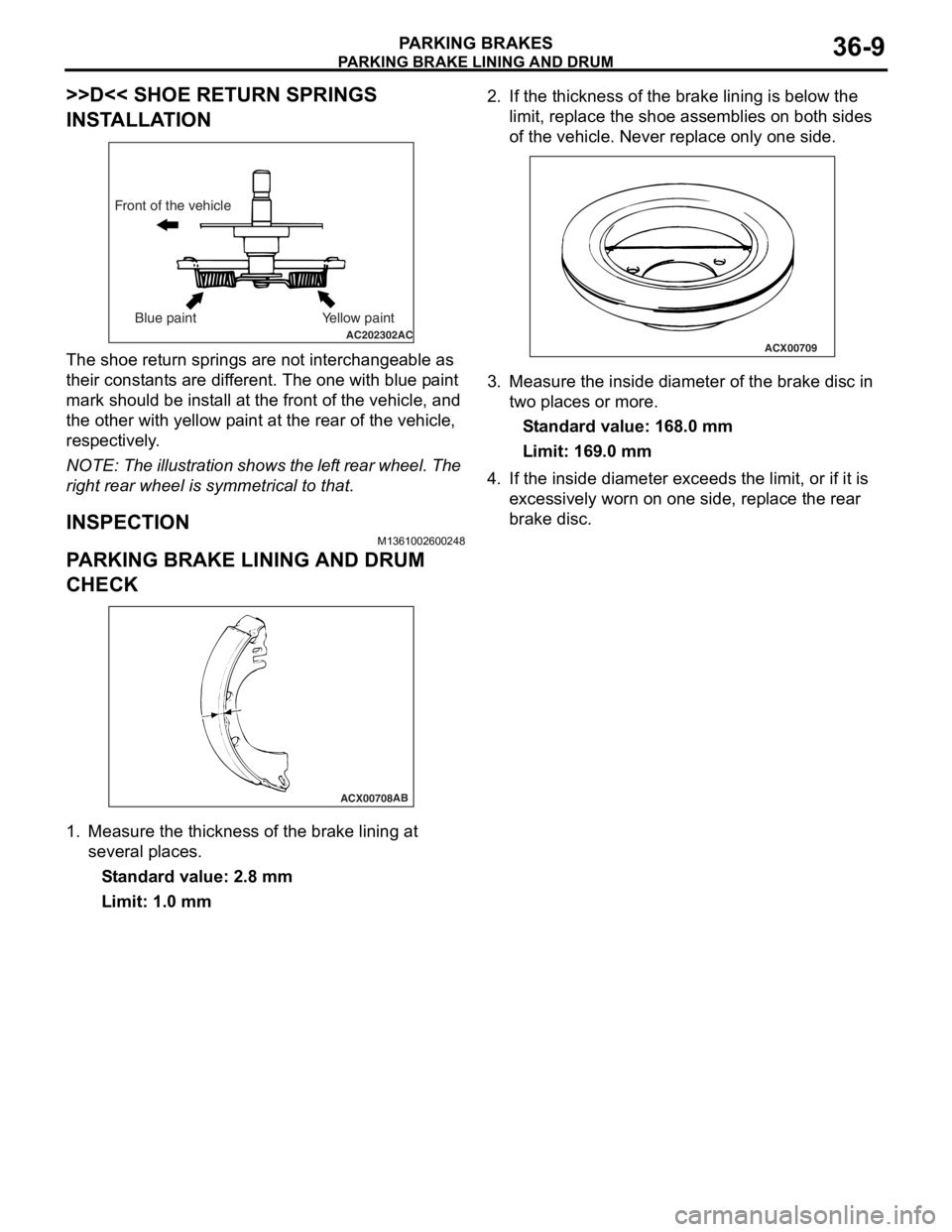
>>D<< SHOE RETURN SPRINGS
INSTALLATION
AC202302AC
Front of the vehicleBlue paint Yellow paint
The shoe ret u rn sp rings are n o t in tercha ngeab le as
their const
a nt s are d i f f e r ent. Th e one with blue p a in t
mark
should be inst a ll at t he fron t o f th e vehicle, and
the oth
e r with yellow p a int a t the re ar of th e ve hicle,
respectively
.
NOTE: The ill ustratio n sh ows th e lef t rear whee l. T he
right re
ar wheel is symme trical to that.
INSPECTION
M13610026 0024 8
PARKING BRAKE LI NING AND DRUM
CHECK
ACX00708AB
1.
Measure the thickne ss of the b r ake lining at
seve ral place s .
St andard va lue: 2.8 mm
Limit: 1.0 mm
2.If the thickness of t he brake linin g is belo w the
limit, rep l ace the shoe a s semblies on bo th sides
o f the vehicle. Ne ver re place only on e side.
ACX00709
3.Measure the inside d i ameter of the bra k e d i sc in
two p l aces o r more .
St andard va lue: 16 8.0 mm
Limit: 169.0 mm
4.If the inside diamete r exceeds the limit, or if it is
e xce ssively worn on one side, rep l ace the re ar
b r ake d i sc.
Page 231 of 800
37-1
GROUP 37
POWER STEERING
CONTENTS
GENERAL INFORMATION . . . . . . . .37-3
SERVICE SPECIFICATIONS . . . . . . .37-6
LUBRICANTS . . . . . . . . . . . . . . . . . .37-7
SEALANTS . . . . . . . . . . . . . . . . . . . .37-7
SPECIAL TOOLS . . . . . . . . . . . . . . . .37-8
ON-VEHICLE SERVICE . . . . . . . . . . .37-11
STEERING WHEEL FREE PLAY CHECK . 37-11
STEERING ANGLE CHECK . . . . . . . . . . . . 37-11
TIE ROD END BALL JOINT TURNING
TORQUE CHECK . . . . . . . . . . . . . . . . . . . . 37-12
STATIONARY STEERING EFFORT
CHECK . . . . . . . . . . . . . . . . . . . . . . . . . . . . 37-12
STEERING WHEEL RETURN TO
CENTRE CHECK . . . . . . . . . . . . . . . . . . . . 37-13
DRIVE BELT TENSION CHECK. . . . . . . . . 37-13
FLUID LEVEL CHECK . . . . . . . . . . . . . . . . 37-13
FLUID REPLACEMENT . . . . . . . . . . . . . . . 37-13
POWER STEERING SYSTEM AIR
BLEEDING . . . . . . . . . . . . . . . . . . . . . . . . . 37-14
OIL PUMP PRESSURE TEST . . . . . . . . . . 37-14
POWER STEERING PRESSURE
SWITCH CHECK . . . . . . . . . . . . . . . . . . . . . 37-15
TIE ROD END BALL JOINT DUST
COVER CHECK . . . . . . . . . . . . . . . . . . . . . 37-15
STEERING COLUMN SHAFT ASSEMBLY
SHOCK ABSORBING MECHANISM
CHECK . . . . . . . . . . . . . . . . . . . . . . . . . . . . 37-15
STEERING WHEEL . . . . . . . . . . . . . .37-17
REMOVAL AND INSTALLATION
REMOVAL AND INSTALLATION
Continued on next page
WARNINGS REGARDING SERVICING OF SUPPLEMENTAL RESTRAINT SYSTEM (SRS) EQUIPPED VEHICLES
WARNING
•Improper service or maintenance of any component of the SRS, or any SRS-related component, can lead to
personal injury or death to service personnel (from inad vertent firing of the air bag) or to the driver and
paassenger (from renderin g the SRS inoperative).
•Service or maintenance of any SRS component or SRS-related component must be performed only at an
authorized MITSUBISHI dealer.
•MITSUBISHI dealer personnel must thoroughly review th is manual, and especially its GROUP 52B - Supplemental
Restraint System (SRS) before begi nning any service or maintenance of any component of the SRS or any
SRS-related component.
NOTE
The SRS includes the following components: SRS air bag control unit, SRS warning light, front impact sensors, air bag module,
clock spring, and interconnecting wiring. Other SRS-related components (that may have to be removed/installed in connection
with SRS service or maintenance) are indicated in the table of contents by an asterisk (*).
Page 233 of 800

GENERAL INFORMATION
POWER STEERING37-3
GENERAL INFORMATION
M1372000100661
Power steering has been adopted in all vehicles to
make the steering system easier to handle.
FEATURES
•A 4-spoke steering wheel is used.
•MOMO leather-wrapped 3-spoke steering wheel
is used.
•A steering column has a shock absorbing mecha-
nism and a tilt steering mechanism.
•Integral-type rack and pinion gear with high rigid-
ity and excellent response is used.
•A vane type pump with a fluid flow rate control
system which change steering effort according to
the engine speed is used.
•The separate plastic resin oil reservoir is used to
reduce weight and to make the fluid level check
-
ing easier.
SPECIFICATIONS
ItemInviteIntense
Steering
wheelTy p e4-spoke typeMOMO leather-wrapped
3-spoke type
Outside diameter mm380365
Maximum number of turns3.193.08
Steering
columnColumn mechanismShock absorbing mechanism and Tilt steering mechanism
Power steering typeIntegral type
Oil pumpTy p eVane pump
Basic discharge amount cm3/rev.7.2 <1300, 1600>
8.1 <2000>
7.2 <1300, 1600>
8.1 <2000>
Relief pressure MPa8.88.8
Reservoir typeSeparate type (plastic)
Pressure switchEquipped
Steering
gearTy p eRack and pinion
Stroke ratio (Rack stroke/Steering
wheel maximum turning radius)45.7445.74
Rack stroke mm146141
Page 234 of 800
GENERAL INFORMATION
POWER STEERING37-4
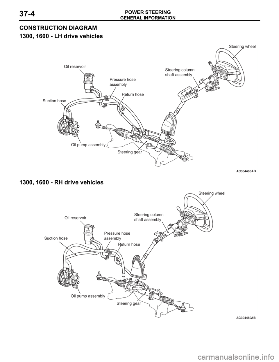
CONSTRUCTION DIAGRAM
1300, 1600 - LH drive vehicles
AC304488AB
Steering wheel
Steering column
shaft assembly
Pressure hose
assembly
Oil reservoir
Suction hose Return hose
Oil pump assembly Steering gear
1300, 1600 - RH drive vehicl es
AC304489AB
Steering wheel
Steering column
shaft assembly
Pressure hose
assembly
Oil reservoir
Suction hose Return hose
Oil pump assembly Steering gear
Page 235 of 800
GENERAL INFORMATION
POWER STEERING37-5
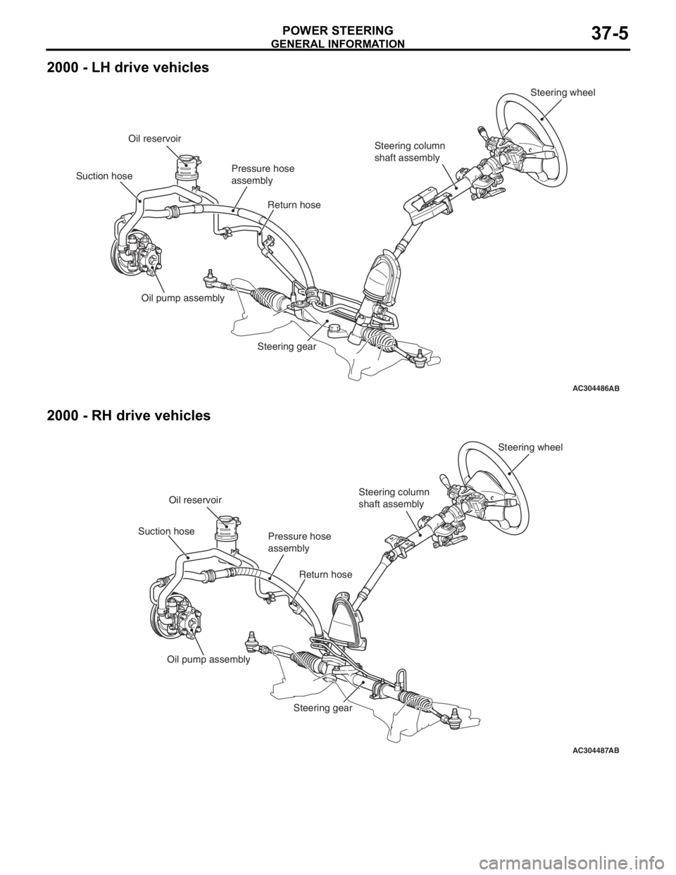
2000 - LH drive vehicles
AC304486AB
Steering wheel
Steering column
shaft assembly
Pressure hose
assembly
Oil reservoir
Suction hose Return hose
Oil pump assembly Steering gear
2000 - RH drive vehicles
AC304487AB
Steering wheel
Steering column
shaft assembly
Pressure hose
assembly
Oil reservoir
Suction hose
Return hose
Oil pump assembly Steering gear
Page 236 of 800

SERVICE SPECIFICATIONS
POWER STEERING37-6
SERVICE SPECIFICATIONS
M1372000300795
ItemStandard valueLimit
Steering wheel free
play mmWith engine running−30
With engine stopped10 or less−
Steering angleInner wheelInvite39°30' ± 1°30'−
Intense (LH drive vehicles)33°40' +1°00'/-2°00'−
Intense (RH drive vehicles)37°00' +1°00'/-2°00'−
Outer wheel
(reference)Invite32°30'−
Intense (LH drive vehicles)28°46'−
Intense (RH drive vehicles)30°00'−
Toe-inAt the centre of tyre tread mm1 ± 2−
Toe-angle (per wheel)0°03' ± 06'−
Tie rod end ball joint turning torque N⋅m0.5 − 2.5−
Tie rod swing resistance N [Tie rod swing torque N⋅m]8 − 27 [1.5 − 4.9]−
Stationary steering effort N [Fluctuation allowance N]29 or less [5.9 or less]−
Oil pump pressure
MPa (750
± 100 r/min.)
Oil pump relief pressure8.8 − 9.5−
Pressure under no-load conditions0.2 − 0.7−
Steering gear retention hydraulic pressure8.8 − 9.5−
Oil pressure switch operating pressure
MPaOFF → ON1.5 − 2.0−
ON → OFF0.7 − 2.0−
Steering gear total pinion torque N⋅m
[Change in torque N
⋅m]
Invite0.8 − 2.1 [0.6 or less]−
Intense0.7 − 2.1 [0.6 or less]−
Opening dimension of special tool boot band crimping tool (MB991561)
mm2.9−
Band crimped width mm2.4 − 2.8−
Page 241 of 800
ON-VEHICLE SERVICE
POWER STEERING37-11
ON-VEHICLE SERVICE
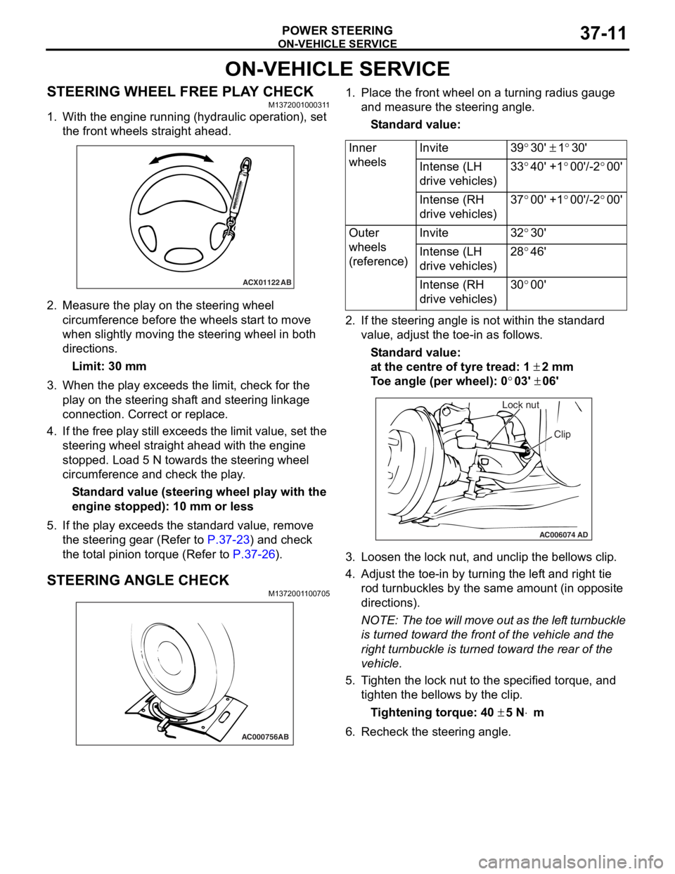
STEERING WHEEL FREE PLAY CHECKM1372001000311
1. With the engine running (hydraulic operation), set the front wheels straight ahead.
ACX01122 AB
2.Measure the play on th e ste e ring wh eel
circumfer ence before the whee ls st a r t to move
when slightly moving the stee ring whe e l in both
direct ions.
Limit: 30 mm
3.Wh en the play exceed s the limit, check fo r the
play on the stee ring shaf t and stee ring linkage
connectio n . Correct or replace .
4.If th e free play still exceeds the limit valu e, set t he
steering wheel stra ight ahead with the engine
stoppe d. Loa d 5 N towards the steer ing whee l
circumfer ence and check the play .
St andard value (steering whee l pla y with the
engine s
t opped): 1 0 mm o r l ess
5.If the play e xce eds the st an dard value , remove
th e ste e ring gear (Refe r to
P.37-23) and check
the tot a l p i nion torqu e (Refer to P.37-26).
STEERING ANGLE CHECKM137200 1 1 0070 5
AC000756AB
1.Place t he fron t wh eel on a tu rning radiu s gau ge
a nd me asure the steering ang le.
St andard va lue:
Inner
wheelsInvite39°30' ± 1°30'
Intense (LH
drive vehicles)33°40' +1°00'/-2°00'
Intense (RH
drive vehicles)37°00' +1°00'/-2°00'
Outer
wheels
(reference)Invite32°30'
Intense (LH
drive vehicles)28°46'
Intense (RH
drive vehicles)30°00'
2.If the steerin g ang le is not within the st a ndard
value , adjust t he toe-in as follows.
St andard va lue:
at the centre of tyre trea d: 1 ± 2 mm
To e angle (p er whee l): 0°03' ± 06'
AC006074 AD
Lock nut
Clip
3.L oose n the lock nut, and un clip the bellows clip .
4.Adjust the toe - in by turning th e lef t an d righ t tie
ro d turnb u ckles by th e sa me a m oun t (in o pposite
directions).
NOTE: The to e will move out as th e lef t turnbuckle
is tur
ned toward the fro n t of th e ve hicle an d the
right tu
rnbuckle is turned toward the rear of the
vehicle.
5. T i ghten the lo ck nut to the specified torque , and
tighten the be llo ws by the clip .
Ti ghte n ing torque: 40 ± 5 N⋅m
6.Recheck the stee ring a ngle .