wheel MITSUBISHI LANCER IX 2006 Owner's Guide
[x] Cancel search | Manufacturer: MITSUBISHI, Model Year: 2006, Model line: LANCER IX, Model: MITSUBISHI LANCER IX 2006Pages: 800, PDF Size: 45.03 MB
Page 188 of 800
ON-VEHICLE SERVICE
FRONT SUSPENSION33-6
ON-VEHICLE SERVICE
FRONT WHEEL ALIGNMENT CHECK AND
ADJUSTMENT
M1331000900886
Measure wheel alignment with alignment equipment
on a level surface. The front suspension, steering
system, wheels, and tyres should be serviced to nor
-
mal condition before measuring wheel alignment.
TOE-IN
Standard value:
At the centre of tyre tread: 1 ± 2 mm
Toe angle (per wheel): 0°03' ± 0°06'
AC006074 AD
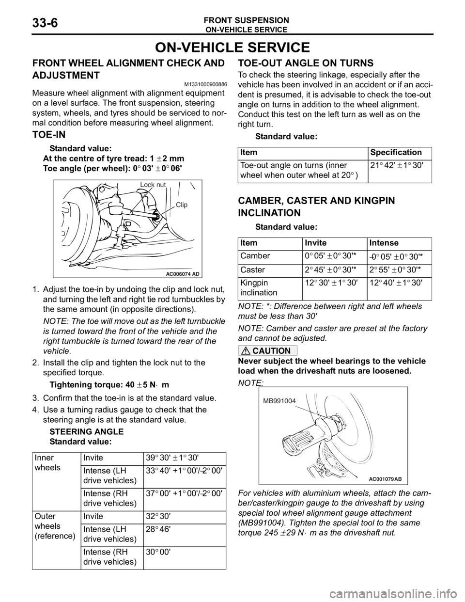
Lock nut
Clip
1.Adjust the to e-in by undoing th e clip and lock nut,
and turning th e lef t and rig h t tie rod turnbu ckles by
th e same amount (in op posite direct ions).
NOTE: The toe will move out as th e lef t turnbuckle
is turn
ed toward the fro n t of th e ve hicle an d the
right tu
rnbuckle is turned t o ward the rear of the
vehicle.
2. In st all the clip and tighten the lock nut to the
specifie d torqu e .
Ti ghte n ing torque: 40 ± 5 N⋅m
3.Conf irm t hat the toe-in is at the st anda rd value.
4.Use a turn ing ra dius gaug e to check tha t the
steering ang le is at the st an dard value .
STEE R I N G AN G L E
St andard va lue:
Inner
wheelsInvite39°30' ± 1°30'
Intense (LH
drive vehicles)33°40' +1°00'/−2°00'
Intense (RH
drive vehicles)37°00' +1°00'/−2°00'
Outer
wheels
(reference)Invite32°30'
Intense (LH
drive vehicles)28°46'
Intense (RH
drive vehicles)30°00'
TO E-OUT ANGLE ON TURNS
To check the stee ring linkage, e s pe cially af ter the
vehicle has been invo
lve d in an accid ent or if an a cci
-
dent is pres umed, it is advisab le to check th e toe-ou t
angle
on tu rns in addition to the wh eel a lig nmen t.
Conduct this test on th e lef t tu rn as we ll a s on the
right turn.
St andard va lue:
ItemSpecification
Toe-out angle on turns (inner
wheel when outer wheel at 20
°)
21°42' ± 1°30'
CAMBER, CASTER AND KINGPIN
INCLINA
T ION
St andard va lue:
ItemInviteIntense
Camber0°05' ± 0°30'*−0°05' ± 0°30'*
Caster2°45' ± 0°30'*2°55' ± 0°30'*
Kingpin
inclination12°30' ± 1°30'12°40' ± 1°30'
NOTE: *: Diffe rence between right and lef t wheels
must be less than 30'
NOTE: Camber and caster are prese t at th e factory
and cannot be adjust ed.
CAUTION
Never subject the wheel bearings to the vehicle
load when the driveshaft nuts are loosened.
NOTE:
AC001079
MB991004
AB
For vehicles with aluminium wheels, attach the cam-
ber/caster/kingpin gauge to the driveshaft by using
special tool wheel alignment gauge attachment
(MB991004). Tighten the special tool to the same
torque 245
± 29 N⋅m as the driveshaft nut.
Page 189 of 800
STRUT ASSEMBLY
FRONT SUSPENSION33-7
LOWER ARM BALL JOINT AXIAL PLAY
CHECK
M1332011300074
1. Raise the vehicle.
2. Remove the stabilizer link from the lower arm.
3. Move the lower arm up and down with your hands to check for an excessive play in the axial
direction of the ball joint. If there is an excessive
play, replace the lower arm assembly.
LOWER ARM BALL JOINT COVER
CHECK
M1332008600321
1. Press the lower arm ball joint cover with your finger to check that there are no cracks or
damage in the lower arm ball joint cover.
2. If the lower arm ball joint cover is cracked or damaged, replace the lower arm assembly.
NOTE: If the lower arm ball joint cover is cracked
or damaged, it is possible that there may also be
damage to the ball joint.
STRUT ASSEMBLY
REMOVAL AND INSTALLATION
M1332001100325
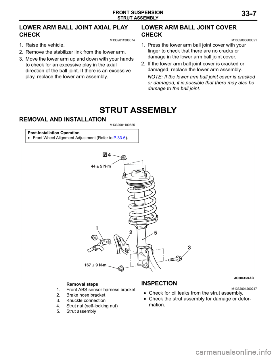
Post-installation Operation
•Front Wheel Alignment Adjustment (Refer to P.33-6).
AC304153
44 ± 5 N·m
1 2
3
4
N
AB
167 ± 9 N·m
5
Removal steps
1.Front ABS sensor
harness bracket
2.Brake hose bracket
3.Knuckle connection
4.Strut nut (self-locking nut)
5.Strut assembly
INSPECTION
M13320012 0024 7
•Check for oil leaks fro m the stru t assemb ly .
•Check the stru t assemb ly for damage o r defor-
mation.
Page 193 of 800
LOWER ARM
FRONT SUSPENSION33-11
LOWER ARM
REMOVAL AND INSTALLATIONM1332001600331
CAUTION
*: Indicates parts which should be temporarily tightened, and then fully tightened with the vehicle on
the earth in an unladen condition.
Post-installation Operation
•Check the lower arm ball join t cover for cracks or damage
by pushing it with your finger.
•Front Wheel Alignment Check and Adjustment (Refer to
P.33-6).
AC006097 AD
7
1
3 4
5
108 ± 10 N·m
186 ± 10 N·m*
7
3
6
N
Specified grease :
Multipurpose grease SAE J310,
NLGI No.2 or equivalent
167 ± 9 N·m
6
2
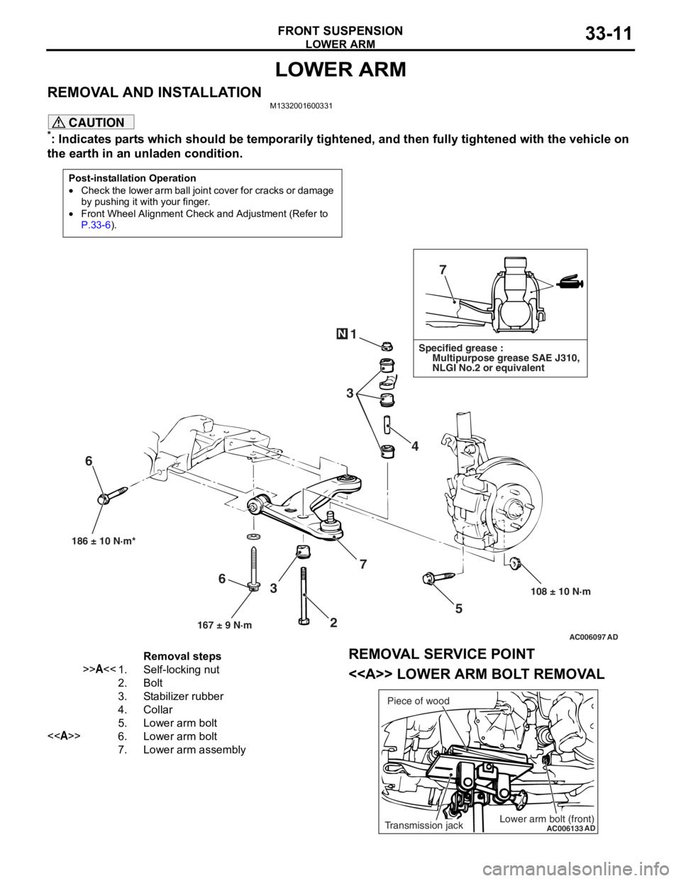
Removal steps
>>A<<1.Self-locking nut
2.Bolt
3.Stabilizer rubber
4.Collar
5.Lower arm bolt
<>6.Lower arm bolt
7.Lower arm assembly
REMOVAL SERVICE POINT
<> LOWER ARM BOLT REMOVAL
AC006133
ADLower arm bolt (front)Transmission jackPiece of wood
Page 196 of 800
STABILIZER BAR
FRONT SUSPENSION33-14
STABILIZER BAR
REMOVAL AND INSTALLATIONM1332004000673
CAUTION
•Before removing the steering wheel and air bag module assembly, refer to GROUP 52B, Service
Precautions
P.52B-5 and Air Bag Module and Clock Spring P.52B-194. Also, put the front wheels in
straight-ahead position. Failure to do so may damage the SRS clock spring and render the SRS air
bag inoperative, which results serious driver injury.
•
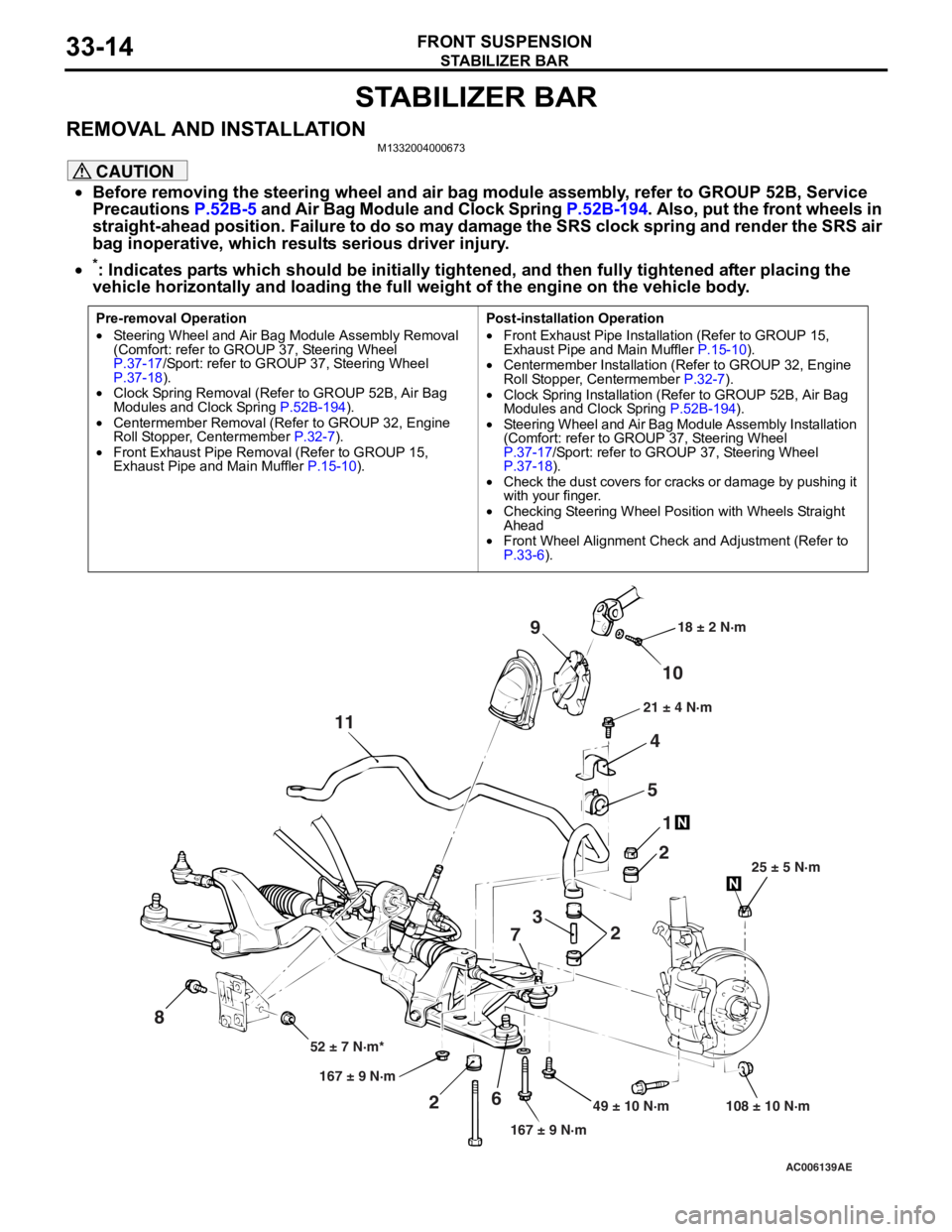
Pre-removal Operation
•Steering Wheel and Air Bag Module Assembly Removal
(Comfort: refer to GROUP 37, Steering Wheel
P.37-17/Sport: refer to GROUP 37, Steering Wheel P.37-18).•Clock Spring Removal (Refer to GROUP 52B, Air Bag
Modules and Clock Spring P.52B-194).
•Centermember Removal (Ref er to GROUP 32, Engine
Roll Stopper, Centermember P.32-7).
•Front Exhaust Pipe Remova l (Refer to GROUP 15,
Exhaust Pipe and Main Muffler P.15-10).
Post-installation Operation
•Front Exhaust Pipe Installation (Refer to GROUP 15,
Exhaust Pipe and Main Muffler P.15-10).•Centermember Installation (Refer to GROUP 32, Engine
Roll Stopper, Centermember P.32-7).
•Clock Spring Installation (Refer to GROUP 52B, Air Bag
Modules and Clock Spring P.52B-194).
•Steering Wheel and Air Bag Module Assembly Installation
(Comfort: refer to GROUP 37, Steering Wheel
P.37-17/Sport: refer to GROUP 37, Steering Wheel P.37-18).•Check the dust covers for cracks or damage by pushing it
with your finger.
•Checking Steering Wheel Position with Wheels Straight
Ahead
•Front Wheel Alignment Check and Adjustment (Refer to P.33-6).
AC006139 AE
49 ± 10 N·m 108 ± 10 N·m
167 ± 9 N·m
167 ± 9 N·m
52 ± 7 N·m* 25 ± 5 N·m
21 ± 4 N·m
18 ± 2 N·m
10
9
4
5 1
2
2
3
7
6
2
11
8
*: Indicates parts which should be initially tightened, and then fully tightened after placing the
vehicle horizontally and loading the full weight of the engine on the vehicle body.
Page 199 of 800
34-1
GROUP 34
REAR SUSPENSION
CONTENTS
GENERAL INFORMATION . . . . . . . .34-2
SERVICE SPECIFICATIONS . . . . . . .34-3
LUBRICANT . . . . . . . . . . . . . . . . . . . .34-3
SPECIAL TOOLS . . . . . . . . . . . . . . . .34-4
ON-VEHICLE SERVICE . . . . . . . . . . .34-6
REAR WHEEL ALIGNMENT CHECK AND
ADJUSTMENT . . . . . . . . . . . . . . . . . . . . . . 34-6
CONTROL LINK PILLOW BALL BUSHING
AXIAL PLAY CHECK
UPPER ARM PILLOW BALL BUSHING
AXIAL PLAY CHECK
LOWER ARM PILLOW BALL BUSHING
AXIAL PLAY CHECK . . . . . . . . . . . . . . . . . 34-7
STABILIZER LINK BALL JOINT DUST
COVER INSPECTION . . . . . . . . . . . . . . . . 34-7
CONTROL LINK, UPPER ARM AND
LOWER ARM . . . . . . . . . . . . . . . . . . .34-8
REMOVAL AND INSTALLATION . . . . . . . . 34-8
INSPECTION. . . . . . . . . . . . . . . . . . . . . . . . 34-9
LOWER ARM BUSHING AND LOWER
ARM PILLOW BALL BUSHING
REPLACEMENT . . . . . . . . . . . . . . . . . . . . . 34-10
TRAILING ARM ASSEMBLY . . . . . . .34-12
REMOVAL AND INSTALLATION . . . . . . . . 34-12
INSPECTION. . . . . . . . . . . . . . . . . . . . . . . . 34-13
TRAILING ARM BUSHING
REPLACEMENT . . . . . . . . . . . . . . . . . . . . . 34-13
SHOCK ABSORBER ASSEMBLY . . .34-14
REMOVAL AND INSTALLATION . . . . . . . . 34-14
INSPECTION. . . . . . . . . . . . . . . . . . . . . . . . 34-15
DISASSEMBLY AND REASSEMBLY . . . . . 34-16
STABILIZER BAR. . . . . . . . . . . . . . . .34-19
REMOVAL AND INSTALLATION . . . . . . . . 34-19
INSPECTION. . . . . . . . . . . . . . . . . . . . . . . . 34-19
STABILIZER LINK BALL JOINT DUST
COVER REPLACEMENT . . . . . . . . . . . . . . 34-20
Page 201 of 800
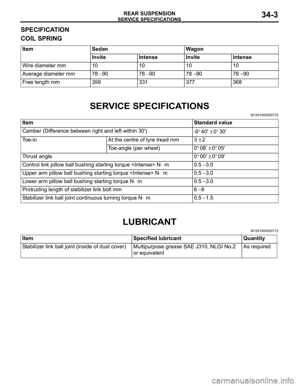
SERVICE SPECIFICATIONS
REAR SUSPENSION34-3
SPECIFICATION
COIL SPRING
ItemSedanWagon
InviteIntenseInviteIntense
Wire diameter mm10101010
Average diameter mm78 − 9078 − 9078 − 9078 − 90
Free length mm359331377368
SERVICE SPECIFICATIONS
M1341000300733
ItemStandard value
Camber (Difference between right and left within 30') −0°40' ± 0°30'
Toe-inAt the centre of tyre tread mm3 ± 2
Toe-angle (per wheel)0°08' ± 0°05'
Thrust angle0°00' ± 0°09'
Control link pillow ball bushing starting torque
Upper arm pillow ball bushing starting torque
Lower arm pillow ball bushing starting torque N⋅m0.5 − 3.0
Protruding length of stabilizer link bolt mm6 − 8
Stabilizer link ball joint continuous turning torque N⋅m0.5 − 1.5
LUBRICANT
M1341000400172
ItemSpecified lubricantQuantity
Stabilizer link ball joint (inside of dust cover)Multipurpose grease SAE J310, NLGI No.2
or equivalentAs required
Page 202 of 800
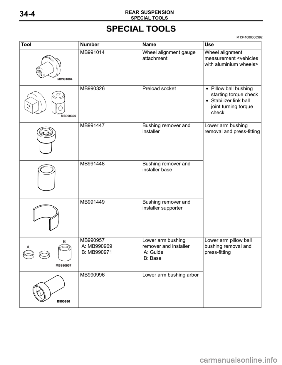
SPECIAL TOOLS
REAR SUSPENSION34-4
SPECIAL TOOLS
M1341000600392
ToolNumberNameUse
MB991004
MB991014Wheel alignme n t gau ge
att
a chmentWheel alig nme n t
measurement
MB990326
MB990326Prel oad socket•Pillow ba ll b u shing
st
a r ting t o rque check
•St abil i ze r lin k ba ll
joint t
u rnin g torque
check
MB991447Bushing remove r and
inst
al lerLo wer arm bushing
re
moval and press-fit t ing
MB991448Bushing remove r and
inst
al ler b a se
MB991449Bushing remove r and
inst
aller suppo rter
MB990957
A B
MB990
957
A: MB9909 69
B: MB990971
Lower arm bushing
remover an
d inst a lle r
A: Guide
B: Base
Lo wer arm pillow ball
b
u shing removal an d
p
r ess-fitting
B990996
MB990 996Lower arm bushing arbor
Page 204 of 800
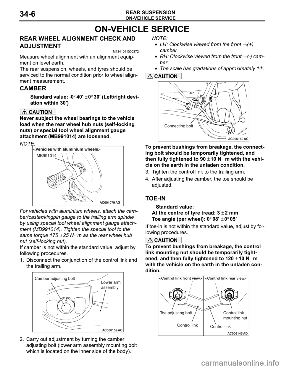
ON-VEHICLE SERVICE
REAR SUSPENSION34-6
ON-VEHICLE SERVICE
REAR WHEEL ALIGNMENT CHECK AND
ADJUSTMENT
M1341011000372
Measure wheel alignment with an alignment equip-
ment on level earth.
The rear suspension, wheels, and tyres should be
serviced to the normal condition prior to wheel align
-
ment measurement.
CAMBER
Standard value: −0°40' ± 0°30' (Left/right devi-
ation within 30')
CAUTION
Never subject the wheel bearings to the vehicle
load when the rear wheel hub nuts (self-locking
nuts) or special tool wheel alignment gauge
attachment (MB991014) are loosened.
NOTE:
AC001079
MB991014
AG
For vehicles with aluminium wheels, attach the cam-
ber/caster/kingpin gauge to the trailing arm spindle
by using special tool wheel alignment gauge attach
-
ment (MB991014). Tighten the special tool to the
same torque 175
± 25 N⋅m as the rear wheel hub
nut (self-locking nut).
If camber is not within the standard value, adjust by
following procedures.
1. Disconnect the conjunction of the control link and the trailing arm.
AC006159 AC
Camber adjusting bolt
Lower arm
assembly
2. Carry out adjustment by turning the camber
adjusting bolt (lower arm assembly mounting bolt
which is located on the inner side of the body).
NOTE: .
•LH: Clockwise viewed from the front → (+)
camber
•RH: Clockwise viewed from the front → (−) cam-
ber
•
AC006160 AC
Connecting bolt
The scale has gradations of approximately 14'.
CAUTION
To prevent bushings from breakage, the connect-
ing bolt should be temporarily tightened, and
then fully tightened to 90
± 10 N⋅m with the vehi-
cle on the earth in the unladen condition.
3. Tighten the control link to the trailing arm.
4. After adjusting the camber, the toe should be
adjusted.
TOE-IN
Standard value:
At the centre of tyre tread: 3 ± 2 mm
Toe angle (per wheel): 0°08' ± 0°05'
If toe-in is not within the standard value, adjust by fol-
lowing procedures.
CAUTION
To prevent bushings from breakage, the control
link mounting nut should be temporarily tight
-
ened, and then fully tightened to 120 ± 10 N⋅m
with the vehicle on the earth in the unladen con
-
dition.
AC006145 AD
Control link
Toe adjusting boltControl link
Control link
mounting nut
Page 206 of 800
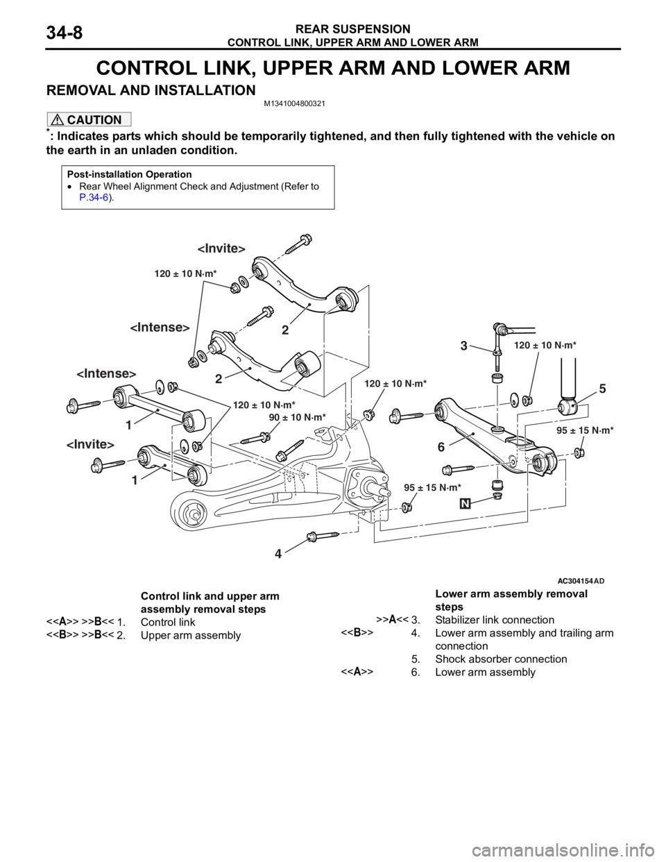
CONTROL LINK, UPPER ARM AND LOWER ARM
REAR SUSPENSION34-8
CONTROL LINK, UPPER ARM AND LOWER ARM
REMOVAL AND INSTALLATIONM1341004800321
CAUTION
*: Indicates parts which should be temporarily tightened, and then fully tightened with the vehicle on
the earth in an unladen condition.
Post-installation Operation
•Rear Wheel Alignment Check and Adjustment (Refer to
P.34-6).
AC304154
1 2
3
4 5
6
AD
120 ± 10 N·m*
95 ± 15 N·m*
120 ± 10 N·m*
120 ± 10 N·m*
95 ± 15 N·m*
90 ± 10 N·m* 120 ± 10 N·m*
N
Control link and upper arm
assembly removal steps
<>>>B<<1.Control link
<>>>B<<2.Upper arm assembly
Lower arm assembly removal
steps
>>A<<3.Stabilizer link connection
<>4.Lower arm assembly and trailing arm
connection
5.Shock absorber connection
<>6.Lower arm assembly
Page 210 of 800
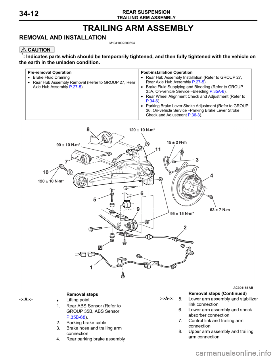
TRAILING ARM ASSEMBLY
REAR SUSPENSION34-12
TRAILING ARM ASSEMBLY
REMOVAL AND INSTALLATIONM1341002200594
CAUTION
*: Indicates parts which should be temporarily tightened, and then fully tightened with the vehicle on
the earth in the unladen condition.
Pre-removal Operation
•Brake Fluid Draining
•Rear Hub Assembly Removal (Refer to GROUP 27, Rear
Axle Hub Assembly P.27-5).
Post-installation Operation
•Rear Hub Assembly Installation (Refer to GROUP 27,
Rear Axle Hub Assembly
P.27-5).
•Brake Fluid Supplying and Bleeding (Refer to GROUP
35A, On-vehicle Service
− Bleeding P.35A-6).
•Rear Wheel Alignment Check and Adjustment (Refer to
P.34-6).
•Parking Brake Lever Stroke Ad justment (Refer to GROUP
36, On-vehicle Service
− Parking Brake Lever Stroke
Check and Adjustment
P.36-3).
AC101449
AC301223
AC304155 AB
90 ± 10 N·m*
120 ± 10 N·m* 95 ± 15 N·m*63 ± 7 N·m
6
7 8
1
10
11
23
4
120 ± 10 N·m*
15 ± 2 N·m
N
9
5
Removal steps
<>•Lifting point
1.Rear ABS Sensor (Refer to
GROUP 35B, ABS Sensor
P.35B-68).
2.Parking brake cable
3.Brake hose and trailing arm
connection
4.Rear parking brake assembly
>>A<<5.Lower arm assembly and stabilizer
link connection
6.Lower arm assembly and shock
absorber connection
7.Control link and trailing arm
connection
8.Upper arm assembly and trailing
arm connection
Removal steps (Continued)