MITSUBISHI LANCER IX 2006 Service Manual
Manufacturer: MITSUBISHI, Model Year: 2006, Model line: LANCER IX, Model: MITSUBISHI LANCER IX 2006Pages: 800, PDF Size: 45.03 MB
Page 321 of 800
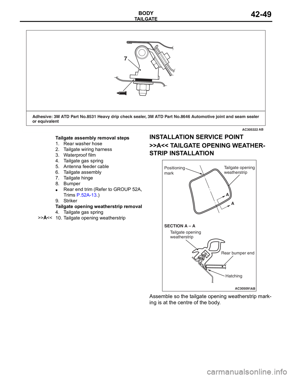
AC305322
Adhesive: 3M ATD Part No.8531 Heavy drip check sealer, 3M ATD Part No.8646 Automotive joint and seam sealer
or equivalent
AB
7
Tailgate assembly removal steps
1.Rear washer hose
2.Tailgate wiring harness
3.Waterproof film
4.Tailgate gas spring
5.Antenna feeder cable
6.Tailgate assembly
7.Tailgate hinge
8.Bumper
•Rear end trim (Refer to GROUP 52A,
Trims
P.52A-13.)
9.Strik er
Tailgate opening weatherstrip removal
4.Tailgate gas spring
>>A<<10.Tailgate opening weatherstrip
TA ILGA TE
BOD Y42-49
INSTALLA T ION SER VICE POINT
>>A<< TA ILGA TE OPENING WEA T HER-
STRIP INSTALLA TION
AC305091
Positioning
mark
AB
Tailgate opening
weatherstrip
Rear bumper end
Tailgate opening
weatherstrip
SECTION A – A A
A
Hatching
Assemble so the t a ilgate o penin g weathe rstrip mark-
ing is at the centre o f the b ody .
Page 322 of 800
TAILGATE
BODY42-50
TAILGATE HANDLE AND LATCH
REMOVAL AND INSTALLATION
M1424001700170
Pre-removal Operation
•Tailgate Handle Play Check (Refer to P.42-47).
Y1518AU
Y1520AU
AC305141
4 5
6
3
3 5
5.0 ± 1.0 N·m
9.0 ± 2.0 N·m
AB
2
1
22 ± 4 N·m
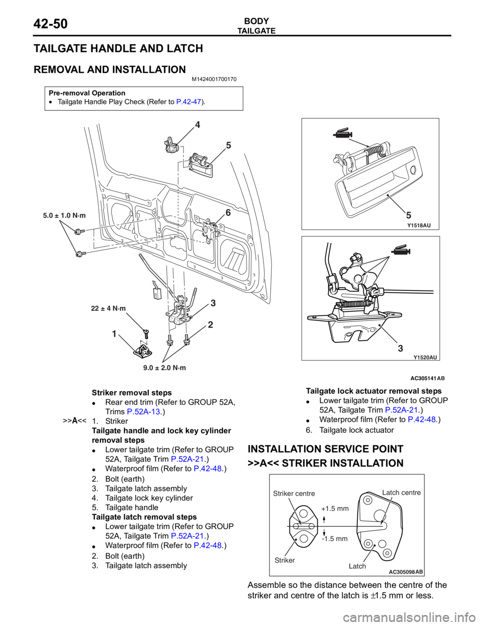
Striker removal steps
•Rear end trim (Refer to GROUP 52A,
Trims
P.52A-13.)
>>A<<1.Strik er
Tailgate handle and lock key cylinder
removal steps
•Lower tailgate trim (Refer to GROUP
52A, Tailgate Trim
P.52A-21.)
•Waterproof film (Refer to P.42-48.)
2.Bolt (earth)
3.Tailgate latch assembly
4.Tailgate lock key cylinder
5.Tailgate handle
Tailgate latch removal steps
•Lower tailgate trim (Refer to GROUP
52A, Tailgate Trim
P.52A-21.)
•Waterproof film (Refer to P.42-48.)
2.Bolt (earth)
3.Tailgate latch assembly
Tailgate lock actuator removal steps
•Lower tailgate trim (Refer to GROUP
52A, Tailgate Trim
P.52A-21.)
•Waterproof film (Refer to P.42-48.)
6.Tailgate lock actuator
INSTALLA T ION SER VICE POINT
>>A<< STRIKER INST ALLA TION
AC305098AB
Striker centre
Striker Latch centre
Latch
+1.5 mm
-1.5 mm
Assemble so the dist ance between the centre of the
striker an
d ce ntre of t he la tch is
±1.5 mm or less.
Page 323 of 800
KEYLESS ENTRY SYSTEM
BODY42-51
INSPECTION
M1424001200142
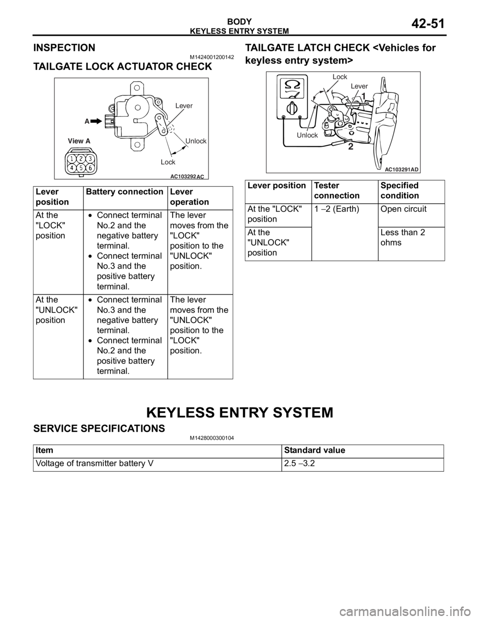
TAILGATE LOCK ACTUATOR CHECK
AC103292
A
View A Unlock
Lock Lever
AC
Lever
positionBatte
ry connec tionLever
o
peration
At the
"LOCK"
position•Conn ect t e rminal
No.2
and th e
ne
gative ba ttery
te
rmin al.
•Connect t e rminal
No.3
and th e
po
sit i ve battery
te
rmin al.
The le ver
moves f
r om the
"LOCK"
p
o sition t o the
"UNLOCK
"
p
o sition.
At the
"UNLOCK"
position•Conn ect t e rminal
No.3
and th e
ne
gative ba ttery
te
rmin al.
•Connect t e rminal
No.2
and th e
po
sit i ve battery
te
rmin al.
The le ver
moves f
r om the
"UNLOCK
"
p
o sition t o the
"LOCK"
p
o sition.
TA ILGA TE LA TCH CHECK
ess entry system>
AC103291
Lever
Unlock Lock
1
2
AD
Lever positionTester
connectionSpecified
condition
At the "LOCK"
position1 − 2 (Earth)Open circuit
At the
"UNLOCK"
positionLess than 2
ohms
KEYLESS ENTR Y SYSTEM
SERV ICE SPECIFICA T IONS
M14280003 0010 4
ItemStandard value
Voltage of transmitter battery V2.5 − 3.2
Page 324 of 800
KEYLESS ENTRY SYSTEM
BODY42-52
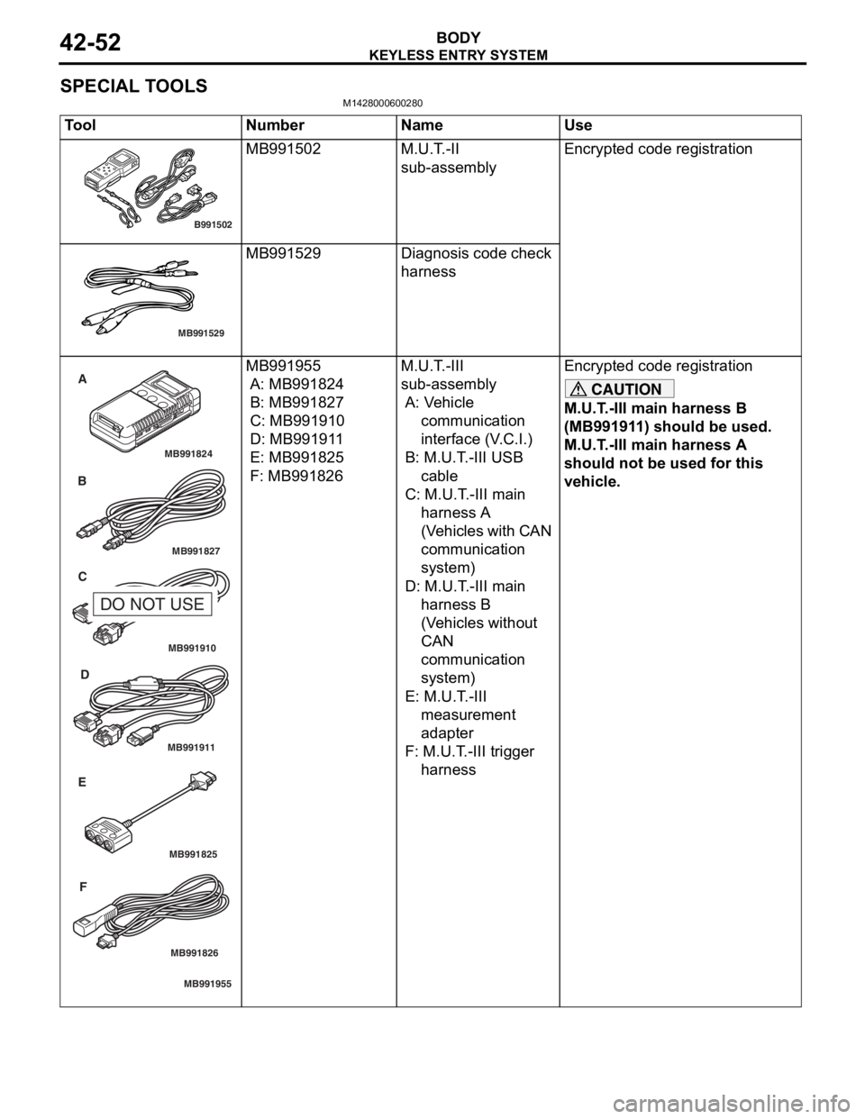
SPECIAL TOOLS
M1428000600280
ToolNumberNameUse
B991502
MB991502M.U.T . -II
su
b-assemblyEn cryp ted code re gistration
MB991529
MB991529Diagnosis code check
harn
e ss
MB991910
MB991826
MB991955
MB991911
MB991824
MB991827
MB991825
A
B C
D
E F
DO NOT USE
MB991 955
A: MB9918 24
B: MB991827
C: MB99191 0
D: MB991911
E: MB991825
F: MB991 826
M.U.T . -III
su
b-assembly
A: V ehicle
commun ica t ion
inte rface (V .C.I.)
B: M.U.T. -III USB
cab l e
C: M.U.T . -III main
harne ss A
(V ehicles wi th CAN
commun ica t ion
sy stem )
D: M.U.T. -III main
harne ss B
(V ehicles witho u t
CA N
commun ica t ion
sy stem )
E: M.U.T. -III
mea s urement
adapt er
F: M.U.T . -III t r igger
harne ss
Encryp ted code re gistration
M.U.T.-III main harness B
(MB991911) should be used.
M.U.T.-III main harness A
should not be used for this
vehicle.
CAUTION
Page 325 of 800
KEYLESS ENTRY SYSTEM
BODY42-53
TROUBLESHOOTING
M1428000700287
The keyless entry system is controlled by the Smart
Wiring System (SWS). For troubleshooting, refer to
GROUP 54B, Troubleshooting
P.54B-15 or GROUP
54C, Troubleshooting P.54C-4.
ON-VEHICLE SERVICE
KEYLESS ENTR Y SYSTEM CHECKM1428001400096
Check the system as described below. If the system
does not work, carry out troubleshooting. Refer to
GROUP 54B, Troubleshooting
P.54B-15, refer to
GROUP 54C, Troubleshooting P.54C-4.
•Operate the transmitter to check that the doors
and tailgate can be locked and unlocked.
•Operate the transmitter to check that the answer-
back function works in response to door and tail-
gate
NOTE: The adjustment function allows you to
change the answerback setting as follows. Prior
to that check, confirm which setting is activated.
.
•The hazard warning lamps flash twice when
locked and once when unlocked. The room
lamp flashes twice when locked and illumi
-
nates for 15 seconds when unlocked.
•The hazard warning lamps do not flash when
locked and flash once when unlocked. The
room lamp flashes twice when locked and illu
-
minates for 15 seconds when unlocked.
•The hazard warning lamps flash twice when
locked and do not flash when unlocked. The
room lamp flashes twice when locked and illu
-
minates for 15 seconds when unlocked.
•The hazard warning lamps do not flash when
both locked and unlocked. The room lamp
flashes twice when locked and illuminates for
15 seconds when unlocked.
KEYLESS ENTRY SYS TEM TIMER LOCK
FUNCTION INSPECTION
M1428004000138
Push the transmitter unlock button and check to see
that the doors and tailgate
seconds. If it doesn't, then execute troubleshooting
remedies. Refer to GROUP 54B, Troubleshooting
P.54B-15, refer to GROUP 54C, Troubleshooting
P.54C-4.
ENABLING/DISABLING THE
ANSWERBACK FUNCTION
M1428003200214
If the keyless entry system locks or unlocks the
doors, the room lamp flashes or illuminates, the haz
-
ard warning lamp flashes (hazard answerback func-
tion). The hazard answerback function can be
enabled or disabled according to the following proce
-
dure:
ENABLING/DISABLING THE HAZARD
ANSWERBACK FUNCTION
The hazard answerback function can be enabled or
disabled by one of the two following procedures.
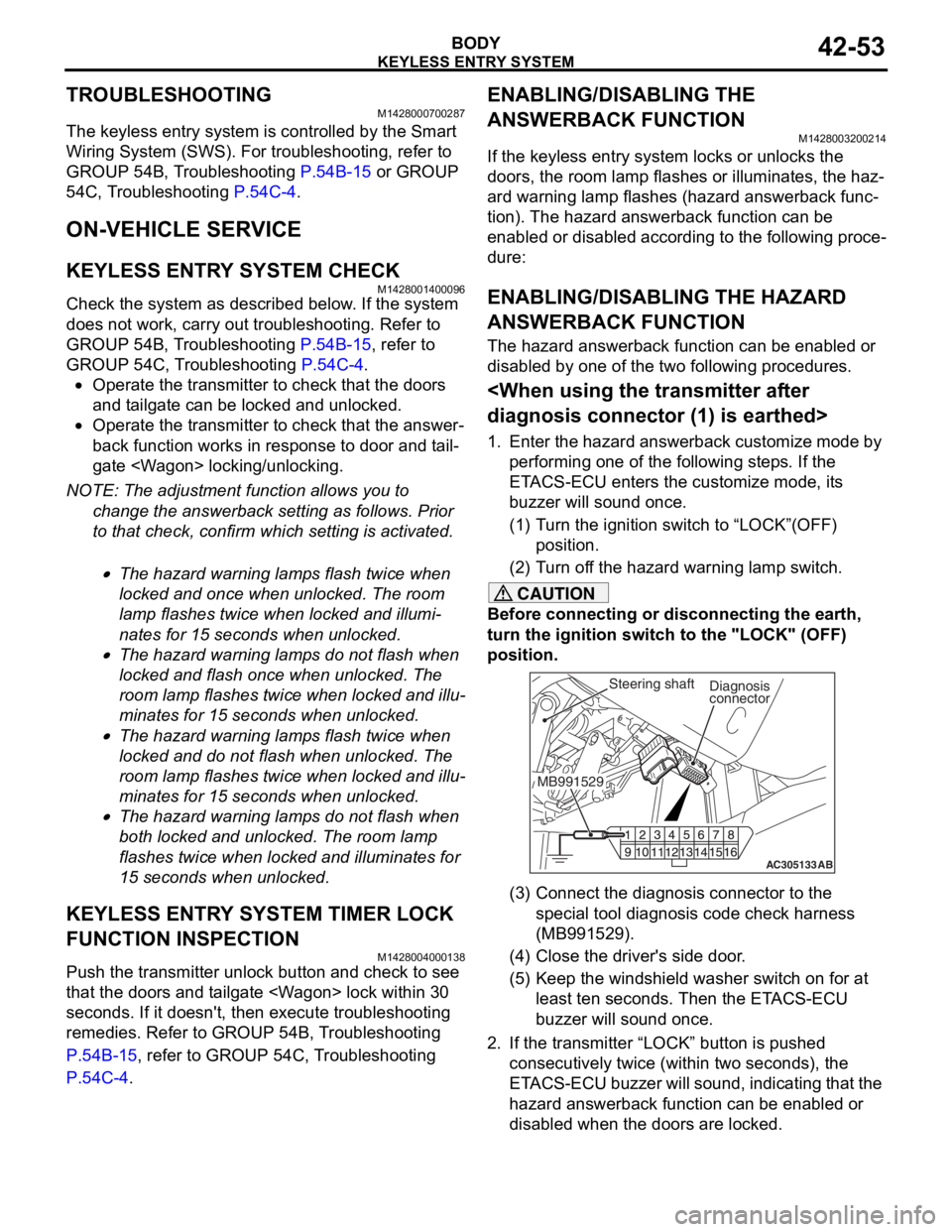
1. Enter the hazard answerback customize mode by performing one of the following steps. If the
ETACS-ECU enters the customize mode, its
buzzer will sound once.
(1) Turn the ignition switch to “LOCK”(OFF) position.
(2) Turn off the hazard warning lamp switch.
CAUTION
Before connecting or disconnecting the earth,
turn the ignition switch to the "LOCK" (OFF)
position.
AC305133AB
Diagnosis
connector
MB991529Steering shaft
(3) Connect the diagnosis connector to the special tool diagnosis code check harness
(MB991529).
(4) Close the driver's side door.
(5) Keep the windshield washer switch on for at least ten seconds. Then the ETACS-ECU
buzzer will sound once.
2. If the transmitter “LOCK” button is pushed consecutively twice (wit hin two seconds), the
ETACS-ECU buzzer will sound, indicating that the
hazard answerback function can be enabled or
disabled when the doors are locked.
Page 326 of 800
KEYLESS ENTRY SYSTEM
BODY42-54
•Enable the hazard answerback function
when the doors are locked: The
ETACS-ECU buzzer will sound once.
•Disable the hazard answerback function
when the doors are locked: The
ETACS-ECU buzzer will sound twice.
3. If the transmitter “UNLOCK” button is pushed consecutively twice (wit hin two seconds), the
ETACS-ECU buzzer will sound, indicating that the
hazard answerback function can be enabled or
disabled when the doors are unlocked.
•Enable the hazard answerback function
when the doors are unlocked: The
ETACS-ECU buzzer will sound once.
•Disable the hazard answerback function
when the doors are unlocked: The
ETACS-ECU buzzer will sound twice.
4. Exit the hazard answer back customize mode by
observing one of the following steps.
(1) Disconnect diagnosis connector terminal (1) form the earth.
(2) Turn the ignition switch to position other then “LOCK”(OFF), or remove the ignition key.
(3) Open the driver's side door.
(4) Any other warning buzzer output occurs.
NOTE: If any operation is not done for at least three
minutes after the ETACS-ECU has entered the cus
-
tomize mode, the hazard answerback customize
mode will be canceled automatically.
connector>
1. Enter the hazard answerback customize mode by performing one of the following steps. If the
ETACS-ECU enters the customize mode, its
buzzer will sound once.
(1) Turn the ignition switch to “LOCK”(OFF) position.
(2) Turn off the hazard warning lamp switch.
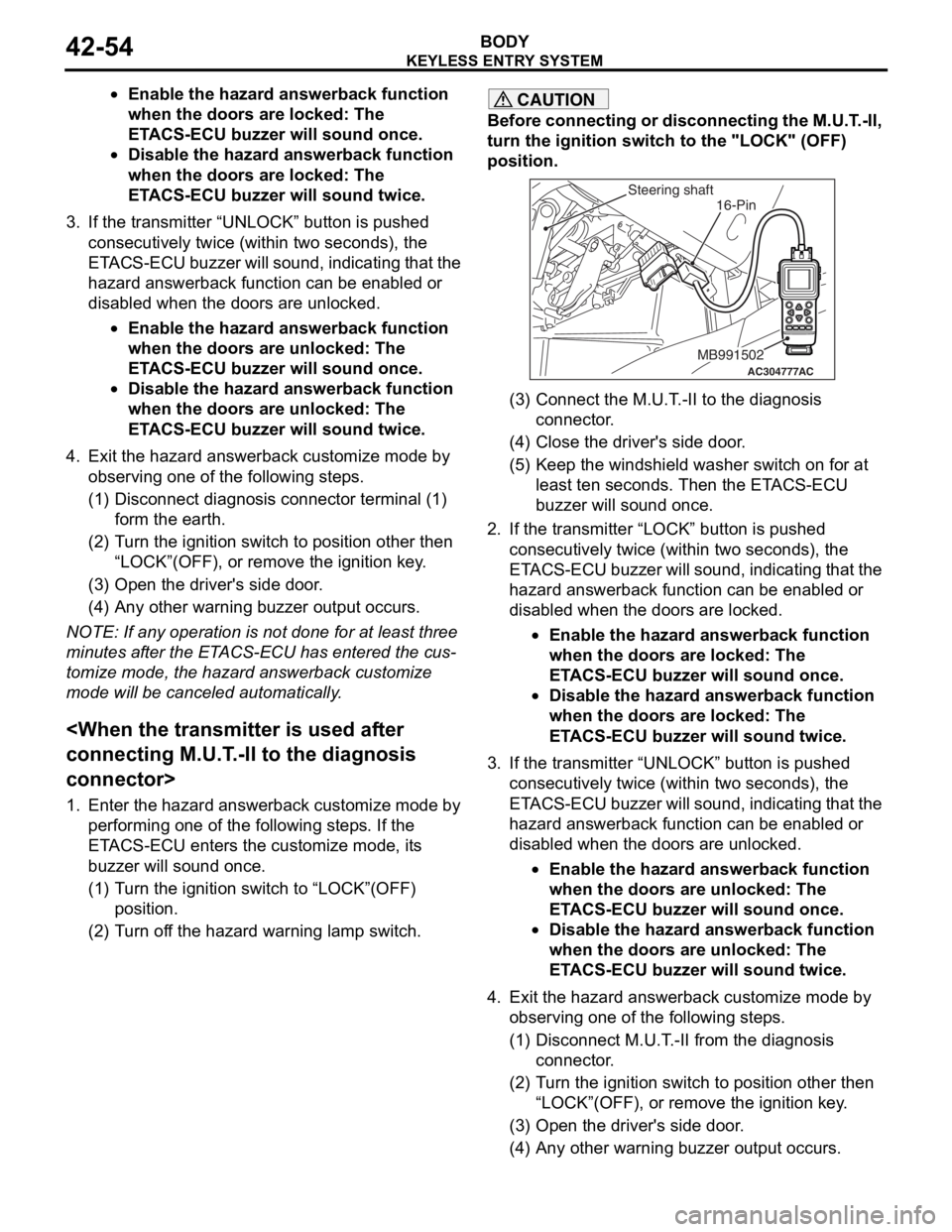
CAUTION
Before connecting or disconnecting the M.U.T.-II,
turn the ignition switch to the "LOCK" (OFF)
position.
AC304777
Steering shaft
ACMB991502
16-Pin
(3) Connect the M.U.T.-II to the diagnosis
connector.
(4) Close the driver's side door.
(5) Keep the windshield washer switch on for at least ten seconds. Then the ETACS-ECU
buzzer will sound once.
2. If the transmitter “LOCK” button is pushed consecutively twice (wit hin two seconds), the
ETACS-ECU buzzer will sound, indicating that the
hazard answerback function can be enabled or
disabled when the doors are locked.
•Enable the hazard answerback function
when the doors are locked: The
ETACS-ECU buzzer will sound once.
•Disable the hazard answerback function
when the doors are locked: The
ETACS-ECU buzzer will sound twice.
3. If the transmitter “UNLOCK” button is pushed consecutively twice (wit hin two seconds), the
ETACS-ECU buzzer will sound, indicating that the
hazard answerback function can be enabled or
disabled when the doors are unlocked.
•Enable the hazard answerback function
when the doors are unlocked: The
ETACS-ECU buzzer will sound once.
•Disable the hazard answerback function
when the doors are unlocked: The
ETACS-ECU buzzer will sound twice.
4. Exit the hazard answer back customize mode by
observing one of the following steps.
(1) Disconnect M.U.T.-II from the diagnosis
connector.
(2) Turn the ignition switch to position other then “LOCK”(OFF), or remove the ignition key.
(3) Open the driver's side door.
(4) Any other warning buzzer output occurs.
Page 327 of 800
KEYLESS ENTRY SYSTEM
BODY42-55
NOTE: If any operation is not done for at least three
minutes after the ETACS-ECU has entered the cus
-
tomize mode, the hazard answerback customize
mode will be canceled automatically.
(MB991824) to the diagnosis connector>
1. Enter the hazard answerback customize mode by
performing one of the following steps. If the
ETACS-ECU enters the customize mode, its
buzzer will sound once.
(1) Turn the ignition switch to “LOCK”(OFF) position.
(2) Turn off the hazard warning lamp switch.
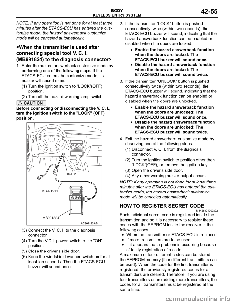
CAUTION
Before connecting or disconnecting the V. C. I.,
turn the ignition switch to the "LOCK" (OFF)
position.
AC305153AB
MB991911
MB991824
16-Pin
(3) Connect the V. C. I. to the diagnosis connector.
(4) Turn the V.C.I. power switch to the "ON" position.
(5) Close the driver's side door.
(6) Keep the windshield washer switch on for at least ten seconds. Then the ETACS-ECU
buzzer will sound once.
2. If the transmitter “LOCK” button is pushed
consecutively twice (wit hin two seconds), the
ETACS-ECU buzzer will sound, indicating that the
hazard answerback function can be enabled or
disabled when the doors are locked.
•Enable the hazard answerback function
when the doors are locked: The
ETACS-ECU buzzer will sound once.
•Disable the hazard answerback function
when the doors are locked: The
ETACS-ECU buzzer will sound twice.
3. If the transmitter “UNLOCK” button is pushed consecutively twice (wit hin two seconds), the
ETACS-ECU buzzer will sound, indicating that the
hazard answerback function can be enabled or
disabled when the doors are unlocked.
•Enable the hazard answerback function
when the doors are unlocked: The
ETACS-ECU buzzer will sound once.
•Disable the hazard answerback function
when the doors are unlocked: The
ETACS-ECU buzzer will sound twice.
4. Exit the hazard answer back customize mode by
observing one of the following steps.
(1) Disconnect V. C. I. from the diagnosis connector.
(2) Turn the ignition switch to position other then
“LOCK”(OFF), or remove the ignition key.
(3) Open the driver's side door.
(4) Any other warning buzzer output occurs.
NOTE: If any operation is not done for at least three
minutes after the ETACS-ECU has entered the cus
-
tomize mode, the hazard answerback customize
mode will be canceled automatically.
HOW TO REGISTER SECRET CODE
M1428001000292
Each individual secret code is registered inside the
transmitter, and so it is necessary to resister these
codes with the EEPROM insi de the receiver in the
following cases.
•When the transmitter or ETACS-ECU is replaced
•If more transmitters are to be used
•If it appears that a probl em is occurring because
of faulty registration of a code.
A maximum of four different codes can be stored in
the EEPROM memory (four different transmitters can
be used). When the code for the first transmitter is
registered, the previously registered codes for all
transmitters are cleared. Therefore, if you are using
four transmitters or are adding more transmitters, the
codes for all transmitters must be registered at the
same time.
Page 328 of 800
KEYLESS ENTRY SYSTEM
BODY42-56
WHEN THE SPECIAL TOOL DIAGNOSIS
CODE CHECK HARNESS (MB991529) IS
USED
1. Check that the doors lock normally when the key is used.
2. Insert the ignition key.
CAUTION
Before connecting or disconnecting the earth,
turn the ignition switch to the "LOCK" (OFF)
position.
AC305133AB
Diagnosis
connector
MB991529Steering shaft
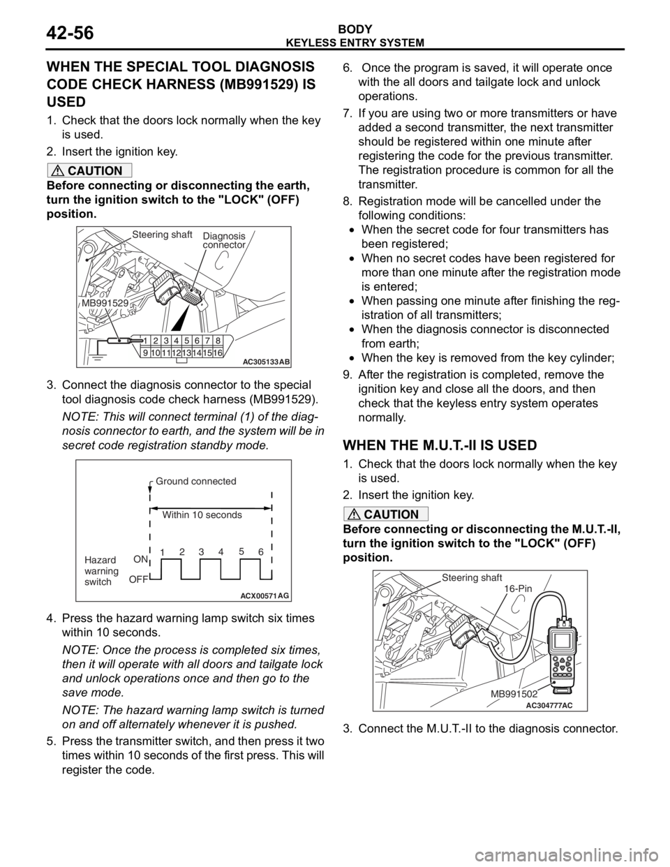
3. Connect the diagnosis connector to the special tool diagnosis code check harness (MB991529).
NOTE: This will connect terminal (1) of the diag-
nosis connector to earth, and the system will be in
secret code registration standby mode.
ACX00571
Ground connected
Within 10 seconds
Hazard
warning
switch ON
OFF 1
23
45
6
AG
4. Press the hazard warning lamp switch six times
within 10 seconds.
NOTE: Once the process is completed six times,
then it will operate with al l doors and tailgate lock
and unlock operations once and then go to the
save mode.
NOTE: The hazard warning lamp switch is turned
on and off alternately whenever it is pushed.
5. Press the transmitter switch, and then press it two times within 10 seconds of the first press. This will
register the code.
6. Once the program is saved, it will operate once
with the all doors and tailgate lock and unlock
operations.
7. If you are using two or more transmitters or have
added a second transmitter, the next transmitter
should be registered within one minute after
registering the code for the previous transmitter.
The registration procedure is common for all the
transmitter.
8. Registration mode will be cancelled under the following conditions:
•When the secret code for four transmitters has
been registered;
•When no secret codes have been registered for
more than one minute after the registration mode
is entered;
•When passing one minute after finishing the reg-
istration of all transmitters;
•When the diagnosis connector is disconnected
from earth;
•When the key is removed from the key cylinder;
9. After the registration is completed, remove the ignition key and close all the doors, and then
check that the keyless entry system operates
normally.
WHEN THE M.U.T.-II IS USED
1. Check that the doors lock normally when the key
is used.
2. Insert the ignition key.
CAUTION
Before connecting or disconnecting the M.U.T.-II,
turn the ignition switch to the "LOCK" (OFF)
position.
AC304777
Steering shaft
ACMB991502
16-Pin
3. Connect the M.U.T.-II to the diagnosis connector.
Page 329 of 800
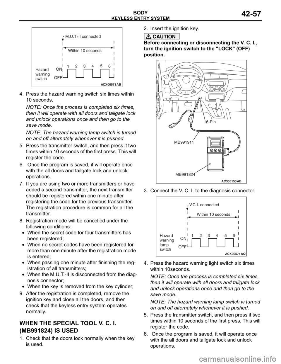
ACX00571
M.U.T.-II connectedWithin 10 seconds
Hazard
warning
switch ON
OFF 1
23
45
6
AB
KEYLE SS ENTR Y SYSTEM
BOD Y42-57
4.Press th e hazard warning switch six times within
10 seconds.
NOTE: Once th e process is comple ted six t i me s,
th
en it
will operate with al l do ors an d t a ilgate lock
an
d unlock opera t ions once and then go to th e
save
mode .
NOTE: The h a zard warnin g lamp switch is turned
on
and o ff alt e rnately when ever it is pushed.
5.Pre s s th e tr ansmitter switch, a nd then pre s s it two
t i mes within 10 second s of th e f i rst pre s s. This will
reg i st er the code.
6. Once the p r ogram is saved, it will opera t e once
wit h the a ll d oors a nd t a ilgate lock and unlo ck
op erations.
7.If you a r e using t w o or mo re transmitters or have
ad ded a second tra n smitter , the n e xt tra n smitter
should be re gistered within o ne minute af ter
reg i st ering the code fo r the pre v io us tra n smitter .
Th e registration pr oced ure is co mmo n for a ll th e
tra n smitter .
8.Registra tion mode will be ca ncelled under the
fo llowing condit i ons:
•When the secr et co de for fo ur transmitters has
bee
n registere d ;
•When no secre t cod e s h a ve b een re gist ered fo r
more tha
n one minute af ter the registration mode
is ente
r ed;
•When p a ssing o ne minute af ter fin i sh ing t he reg-
istration of all t r ansmitte rs;
•When the M.U.T . -II is d i sconne cted from th e dia g-
nosis connecto r;
•When the key is re moved fro m the key cylin der;
9.Af ter the registration is completed, remove the
ignition key a nd close all the d oors, and th en
check tha t the keyless entry syste m op erates
no rmally .
WH EN THE SPECIAL T O OL V . C. I.
(
M B991824) I S USED
1.Check t hat the doors lock n o rmally wh en the key
is used.
2. In sert t he ig nition ke y .
CAUTION
Before connecting or disconnecting the V. C. I.,
turn the ignition switch to the "LOCK" (OFF)
position.
AC305153AB
MB991911
MB991824
16-Pin
3. Connect the V. C. I. to the diagnosis connector.
ACX00571
Within 10 seconds
Hazard
warning
lamp
switch ON
OFF 1234 56
AQ
V.C.I. connected
4. Press the hazard warning
light switch six times
within 10seconds.
NOTE: Once the process is completed six times,
then it will operate with all doors and tailgate lock
and unlock operations once and then go to the
save mode.
NOTE: The hazard warning lamp switch is turned
on and off alternately whenever it is pushed.
5. Press the transmitter switch, and then press it two times within 10 seconds of the first press. This will
register the code.
6. Once the program is saved, it will operate once with the all doors and tailgate lock and unlock
operations.
Page 330 of 800
KEYLESS ENTRY SYSTEM
BODY42-58
7. If you are using two or more transmitters or have added a second transmitter, the next transmitter
should be registered within one minute after
registering the code for the previous transmitter.
The registration procedure is common for all the
transmitter.
8. Registration mode will be cancelled under the following conditions:
•When the secret code for four transmitters has
been registered;
•When no secret codes have been registered for
more than one minute after the registration mode
is entered;
•When passing one minute after finishing the reg-
istration of all transmitters;
•When the V.C.I. is disconnected from the diagno-
sis connector;
•When the key is removed from the key cylinder;
9. After the registration is completed, remove the ignition key and close all the doors, and then
check that the keyless entry system operates
normally.
TRANSMITTER
DISASSEMBLY AND REASSEMBLY
M1428002800172
Post-reassembly operation
•Transmitter operation check
AC310838AC303199
AC3041181
2
AF
5
3
4
6
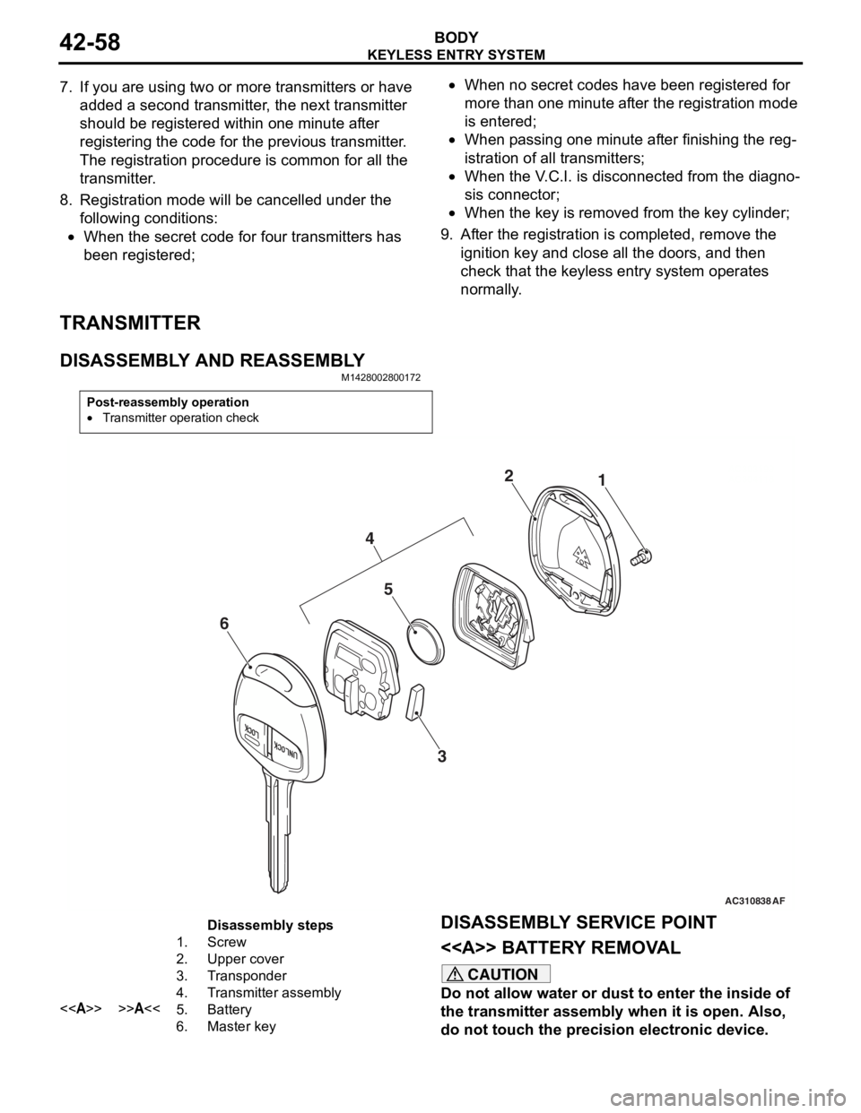
Disassembly steps
1.Screw
2.Upper cover
3.Transponder
4.Transmitter assembly
<>>>A<<5.Battery
6.Master key
DISASSEMBL Y SER V ICE POINT
<> BATTER Y REMOV A L
CAUTION
Do not allow water or dust to enter the inside of
the transmitter assembly when it is open. Also,
do not touch the precision electronic device.