MITSUBISHI LANCER IX 2006 Service Manual
Manufacturer: MITSUBISHI, Model Year: 2006, Model line: LANCER IX, Model: MITSUBISHI LANCER IX 2006Pages: 800, PDF Size: 45.03 MB
Page 301 of 800
DOOR
BODY42-29
3. If the operation current is outside the standard value, refer to GROUP 54B, Troubleshooting
P.54B-15, refer to GROUP 54C, Troubleshooting
P.54C-4.
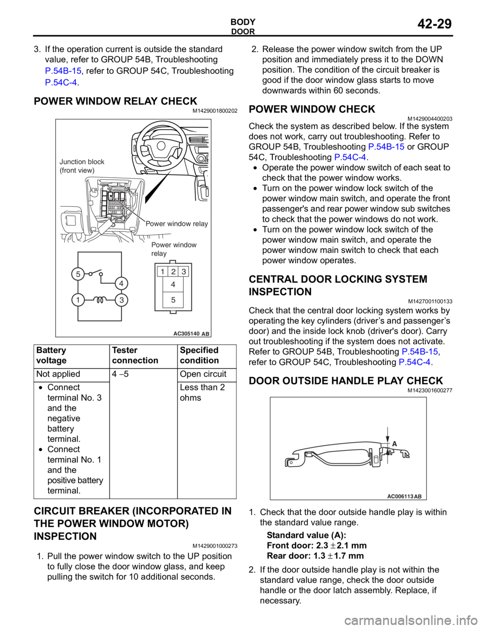
POWER WINDOW RELAY CHECKM1429001800202
AC305140
123
4
5
1 3
4
5
AB
Junction block
(front view)
Power window relayPower window
relay
Bat t ery
voltage
Teste r
co
nnectionSpecified
condition
Not applied4 − 5Ope n ci rcui t
•Connect
te
rmin al No. 3
an
d the
ne
gative
ba
ttery
te
rmin al.
•Connect
te
rmin al No. 1
an
d the
positive batt
e ry
te
rmin al.
Less than 2
ohms
CIRCUIT BREAKER (INCORPORA T ED IN
THE POW
E R W I NDOW MOT O R)
INSPECTION
M14290010 0027 3
1.Pull the p o wer windo w switch to th e UP position
to f u lly close the do or windo w g l ass, an d ke ep
pullin g the switch for 1 0 addition al secon d s.
2.Rele ase the power window switch from t he UP
position an d immediately pre ss it to t he DOW N
position. Th e con d ition of the circu i t brea ker is
goo d if t he doo r window g l ass st art s to mo ve
downward s with in 60 seconds.
POWER WI NDOW CHECKM14290044 0020 3
Check the system a s de scribed b e low . I f the system
does not work, car
r y out troublesh ootin g. Refer to
GROUP 54
B, T r ouble s hoo ting
P.54B-15 or GROUP
54C, T r oublesh ootin g P.54C-4.
•Operate the powe r wind ow switch of e a ch se at to
check that
the power window works.
•Tu rn o n the power wind ow lock switch of the
power wind
ow main swit ch, and ope rate the front
p
a ssenger's and rear power window su b switches
to check th
at the p o wer windo ws do n o t work.
•Tu rn o n the power wind ow lock switch of the
power
window main switch, and operate the
power
window main switch to check tha t each
power window
op erates.
CENTRAL DOOR LOCKING SYSTEM
INSPECTION
M142700 1 1 0013 3
Check that th e ce ntral door locking system wo rks by
op
er atin g th e key cylin de rs (d rive r ’ s an d p a sse n g e r ’ s
door) an
d the inside lock kno b (driver's door). Ca rry
out trou
bleshooting if the system does not activate.
Re
fer to GROUP 54B, T r ou bleshooting
P.54B-15,
refer to GROUP 54 C, T r o uble s hoo ting P.54C-4.
DOOR OUTSIDE HANDLE PL A Y CHECKM14230016 0027 7
AC006113
AB
A
1.Check t hat the door o u t s ide handle play is with in
th e st and ard va lue range.
St andard va lue (A):
Fron t door: 2.3 ± 2.1 m m
Rear door: 1.3 ± 1.7 mm
2. If the do or out side ha ndle play is not wit h in th e
st a ndard valu e rang e, ch eck the do or out side
h andle or the door latch assemb ly . Replace, if
ne c e ss a r y .
Page 302 of 800
DOOR
BODY42-30
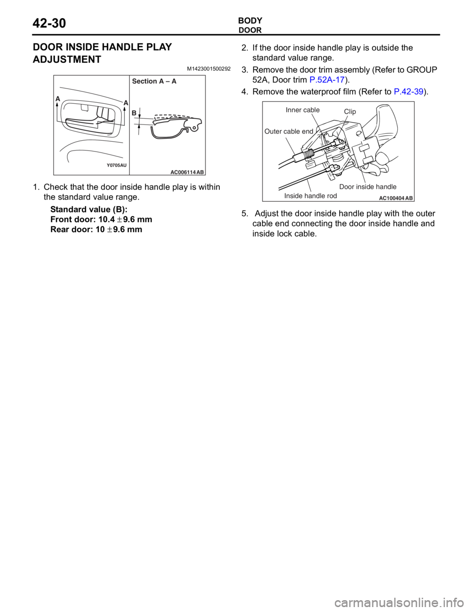
DOOR INSIDE HANDLE PLAY
ADJUSTMENT
M1423001500292
AC006114Y0705AUAB
AA
BSection A – A
1.
Check t hat the door insi de ha ndle play is within
th e st and ard va lue ra nge.
St andard va lue (B):
Fron t door: 10. 4 ± 9.6 mm
Rear door: 10 ± 9.6 mm
2.If the do or inside handle play is ou t s ide the
st a ndard valu e rang e.
3. Remo ve the d oor trim a ssembly (Refer to GROUP
5 2 A, Door trim
P.52A-17).
4.Remove the wate rproof film (Re f er to P.42-39).
AC100404
AB
Clip
Inner cable
Outer cable end
Inside handle rod Door inside handle
5.
Adjust the do or inside handle play wit h the o u ter
cable end conne cting the door inside han dle a nd
inside lo ck cable.
Page 303 of 800
DOOR
BODY42-31
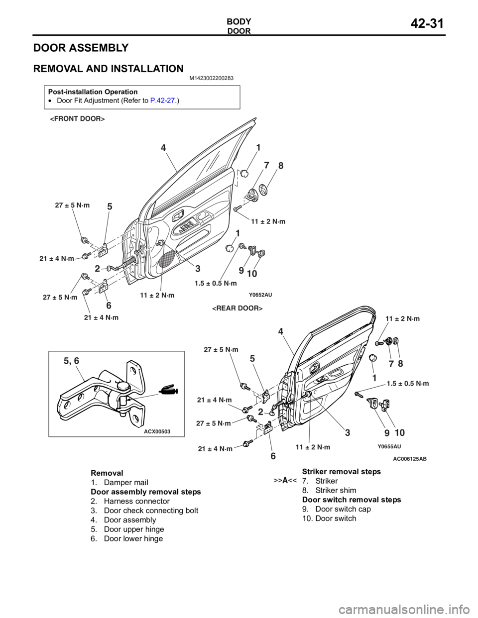
DOOR ASSEMBLY
REMOVAL AND INSTALLATION
M1423002200283
Post-installation Operation
•Door Fit Adjustment (Refer to P.42-27.)
Y0655AUAC006125
ACX00503
Y0652AU
5, 6
AB
1
2 3
4
5
6 7
8
9 10
1
23 4
5
6 7
8
9 10
11.5 ± 0.5 N·m
1.5 ± 0.5 N·m
11 ± 2 N·m 11 ± 2 N·m
11 ± 2 N·m
11 ± 2 N·m
21 ± 4 N·m 27 ± 5 N·m
21 ± 4 N·m
27 ± 5 N·m
21 ± 4 N·m
27 ± 5 N·m
21 ± 4 N·m
27 ± 5 N·m
Removal
1.Damper mail
Door assembly removal steps
2.Harness connector
3.Door check connecting bolt
4.Door assembly
5.Door upper hinge
6.Door lower hinge
Striker removal steps
>>A<<7.Striker
8.Striker shim
Door switch removal steps
9.Door switch cap
10.Door switch
Page 304 of 800
DOOR
BODY42-32
INSTALLATION SERVICE POINT
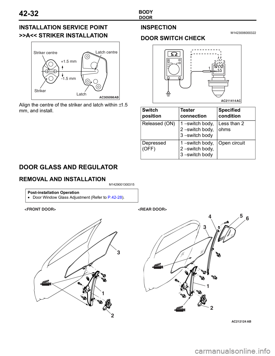
>>A<< STRIKER INSTALLATION
AC305098AB
Striker centreStriker Latch centre
Latch
+1.5 mm
-1.5 mm
Align the centre o f the striker and latch within ±1.5
mm,
and inst
all.
INSPECTION
M1423 0060 0032 2
DOOR SWITCH CHECK
AC211414
123
AC
Switch
positionTester
connectionSpecified
condition
Released (ON)1 − switch body,
2
− switch body,
3
− switch body
Less than 2
ohms
Depressed
(OFF)1 − switch body,
2
− switch body,
3
− switch body
Open circuit
DOOR GLASS AND REGULA T O R
REMOVA L AND INST ALLA TIONM14290013 0031 5
Post-installation Operation
•Door Window Glass Adjustment (Refer to P.42-28).
AC212124AB
1
23
12
3
4
5
6
Page 305 of 800
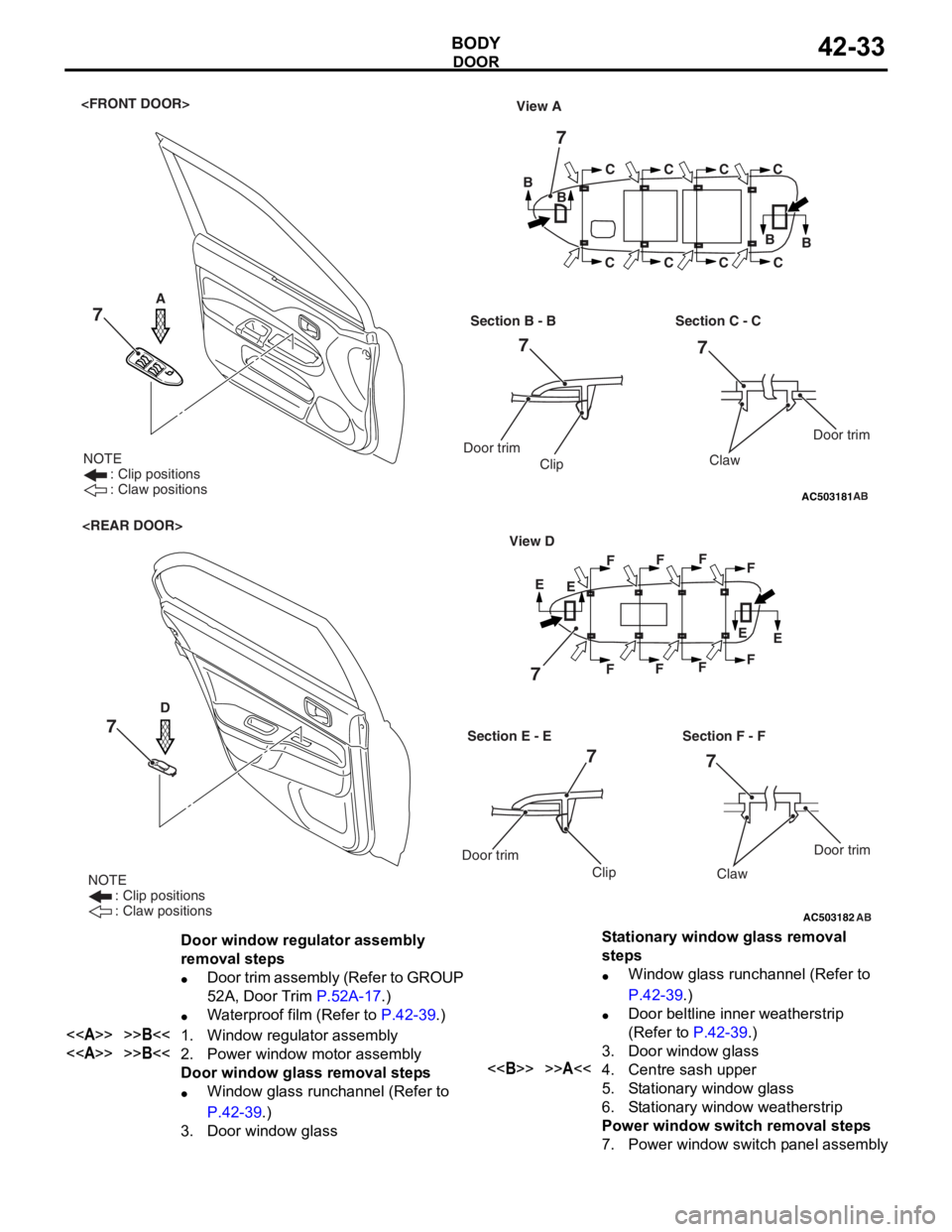
AC503181
NOTE
: Clip positions
: Claw positions
View A
BB
BB
C
C C
CC
C C
C
Section B - B
Door trim
Clip
Section C - C
AB
Door trim
Claw
7
77
7
A
AC503182
NOTE
: Clip positions
: Claw positions
E
E
EE
F
F F
F F
F F
F
Section E - E View D
Door trim
Clip
Section F - F
Door trim
Claw
D
7
7
7
AB
7
Door window regulator assembly
removal steps
•Door trim assembly (Refer to GROUP
52A, Door Trim
P.52A-17.)
•Waterproof film (Refer to P.42-39.)
<>>>B<<1.Window regulator assembly
<>>>B<<2.Power window motor assembly
Door window glass removal steps
•Window glass runchannel (Refer to
P.42-39.)
3.Door window glass
Stationary window glass removal
steps
•Window glass runchannel (Refer to
P.42-39.)
•Door beltline inner weatherstrip
(Refer to
P.42-39.)
3.Door window glass
<>>>A<<4.Centre sash upper
5.Stationary window glass
6.Stationary window weatherstrip
Power window switch removal steps
7.Power window switch panel assembly
DOOR
BO
D Y42-33
Page 306 of 800
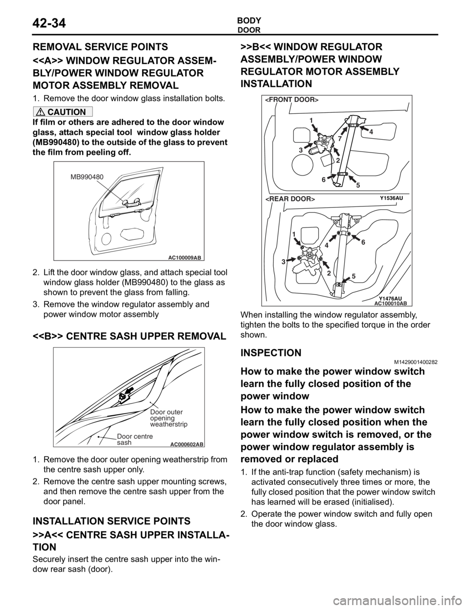
Page 307 of 800

DOOR
BODY42-35
CAUTION
The anti-trap function does not work until the
power window switch completes learning the
fully closed position (It is because the anti-trap
function is reset).
3. Operate the power window switch and fully close
the door window glass. The power window
activates for 0.7 seconds and stops automatically
when the power window switch is pressed once.
Repeat this operation until the door window glass
fully closes and release the switch once. Then,
hold the power window switch to the fully closed
side again for one second so that the power
window switch completes learning the fully closed
position.
NOTE: If the power window switch is operated to
open the door window glass while the switch is
learning, learning will be cancelled. If this hap
-
pens, return to step 2.
How to make the power window switch
learn the fully closed position when the
power window switch is replaced with a
new one
CAUTION
The anti-trap function does not work until the
power window switch completes learning the
fully closed position (It is because the anti-trap
function is reset).
Operate the power window main switch to fully close
the door window glass by one-shot up action so that
the power window switch will complete learning (Ini
-
tialisation is not needed).
NOTE: When the power window sub switch of each
seat is replaced, operate the power window main
switch to fully close the applicable power window by
one-shot up action (It is because the power window
sub switch does not have one-shot up/down func
-
tion).
Page 308 of 800
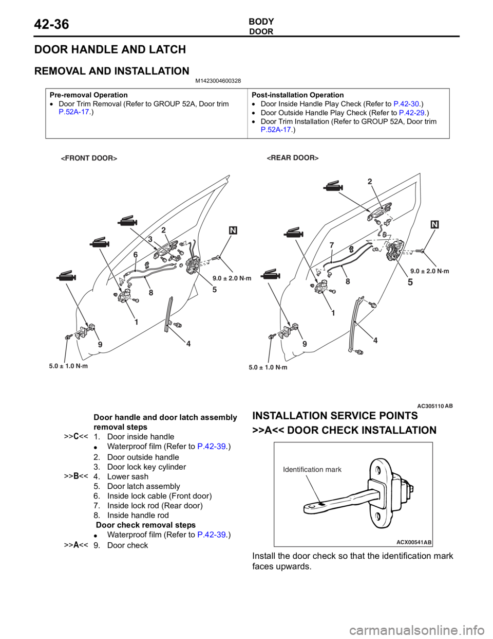
DOOR
BODY42-36
DOOR HANDLE AND LATCH
REMOVAL AND INSTALLATION
M1423004600328
Pre-removal Operation
•Door Trim Removal (Refer to GROUP 52A, Door trim P.52A-17.)
Post-installation Operation
•Door Inside Handle Play Check (Refer to P.42-30.)
•Door Outside Handle Play Check (Refer to P.42-29.)
•Door Trim Installation (Refer to GROUP 52A, Door trim
P.52A-17.)
AC305110
5
5.0 ± 1.0 N·m
1
4
9
2
AB
4 5
2
3
8 7
5.0 ± 1.0 N·m
1
6
9
NN
89.0 ± 2.0 N·m 9.0 ± 2.0 N·m
Door handle and door latch assembly
removal steps
>>C<<1.Door inside handle
•Waterproof film (Refer to P.42-39.)
2.Door outside handle
3.Door lock key cylinder
>>B<<4.Lower sash
5.Door latch assembly
6.Inside lock cable (Front door)
7.Inside lock rod (Rear door)
8.Inside handle rod
Door check removal steps
•Waterproof film (Refer to P.42-39.)
>>A<<9.Door check
INST
ALLA T ION SER VICE POINTS
>>A<< DOOR CHECK INST ALLA TION
ACX00541
Identification mark
AB
Install the d oor check so that th e ide n tification mark
faces upward
s .
Page 309 of 800
ItemIdentification
mark
Front DoorLeft door39L
Right door39R
Rear DoorLeft door40L
Right door40R
DOOR
BODY42-37
>>B<< LOWER SASH INSTALLATION
Securely insert the rear lower sash into the window
rear sash.
>>C<< DOOR INSIDE HANDLE
INSTALLATION
AC100404AB
Clip
Inner cable
Outer cable end
Inside handle rod Door inside handle
1.
In st all the inside lo ck cable to th e doo r inside
ha ndle as fo llo ws:
(1)I nst a ll the inne r cab l e en d in the in sid e lock
cab l e to the clip in th e door inside h andle .
(2)T urn the inside lock knob to the do or lock
positio n.
(3)I nst a ll the outer cable end to the door inside
hand le secure ly .
(4)I nst a ll the clip to the in ner cable .
2.In st all the inside han dle ro d to th e door inside
ha ndle .
3.In st all the do or inside handle to t he doo r .
INSPECTION
M14230047 0039 2
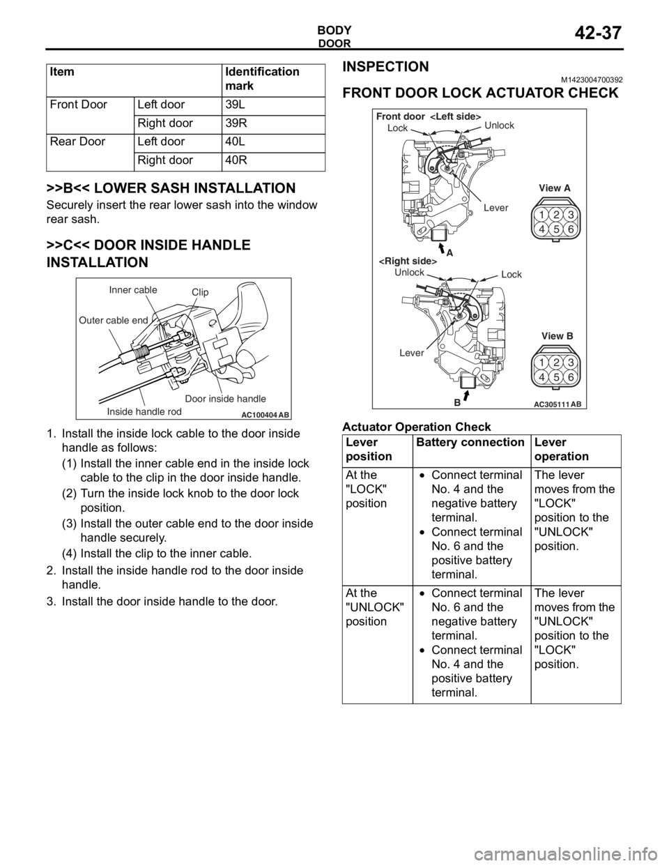
FRONT DOOR LOCK ACTUA T O R CHECK
42
53
6
1
4 2
53
6
1
AC305111B
A
AB
Lock
Unlock
View A
View B
Unlock
Lock
Front door
Lever
Ac tuator Op era t ion Check
Lever
positionBattery connectionLever
operation
At the
"LOCK"
position•Connect terminal
No. 4 and the
negative battery
terminal.
•Connect terminal
No. 6 and the
positive battery
terminal.
The lever
moves from the
"LOCK"
position to the
"UNLOCK"
position.
At the
"UNLOCK"
position•Connect terminal
No. 6 and the
negative battery
terminal.
•Connect terminal
No. 4 and the
positive battery
terminal.
The lever
moves from the
"UNLOCK"
position to the
"LOCK"
position.
Page 310 of 800

DOOR
BODY42-38
Actuator Switch Check
Lever positionTester
connectionSpecified
condition
At the "LOCK"
position1 − 2Less than 2
ohms
1 − 3Open circuit
At the "UNLOCK"
position1 − 2Open circuit
1 − 3Less than 2
ohms
REAR DOOR LOCK ACTUATOR CHECK
23
4 1
56
23
4 1
56
AC305112B
A
AB
Rear door
Lock Unlock
View A
View B
Unlock
Lock
Lever
Ac tuator Op era t ion Check
Lever
positionBattery connectionLever
operation
At the
"LOCK"
position•Connect terminal
No. 4 and the
negative battery
terminal.
•Connect terminal
No. 6 and the
positive battery
terminal.
The lever
moves from the
"LOCK"
position to the
"UNLOCK"
position.
At the
"UNLOCK"
position•Connect terminal
No. 6 and the
negative battery
terminal.
•Connect terminal
No. 4 and the
positive battery
terminal.
The lever
moves from the
"UNLOCK"
position to the
"LOCK"
position.
DOOR LOCK KEY CYLINDER SWITCH
CHECK
AC101318
3
2
1
Switch
positionTester
connectionSpecified
condition
LOCK2 − 3Less than 2
ohms
NEUTRAL
(OFF)1 − 2, 2 − 3Open circuit
UNLOCK1 − 2Less than 2
ohms