MITSUBISHI LANCER IX 2006 Service Manual
Manufacturer: MITSUBISHI, Model Year: 2006, Model line: LANCER IX, Model: MITSUBISHI LANCER IX 2006Pages: 800, PDF Size: 45.03 MB
Page 341 of 800
MOULDINGS
EXTERIOR51-9
ADHESIVE
M1511000500749
ApplicationSpecified adhesive
Front fender, front and rear door mouldingsDouble-sided tape: Generic products
[a: 6 mm width 1.2 mm thickness, b: 20 mm width 1.2
mm thickness]
MOULDINGS
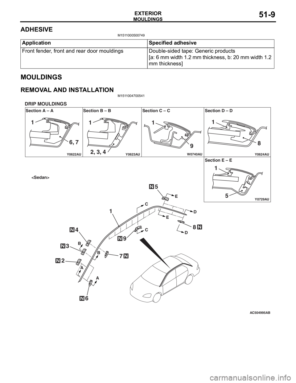
REMOVAL AND INSTALLATIONM1511004700541
AC504995
Y0622AU
Y0624AUY0623AU
Y0729AU
W0740AU
Section A – A
DRIP MOULDINGS
Section B – B Section C – C Section D – D
Section E – E
AB
N
N
N
N
N
CC
E E
D
D
B
B
A
A
1
2
6
4
3
5
7
8
9
N
N
N
111
9 8
51
1
6, 7 2, 3, 4
Page 342 of 800
AC304340
1
1
AA
AA
AB
B
B
C
C
C
C
B B
N
N
N
2
N2
4
3
N3
N4
N
6
9
7
N
6N
N
7N
N9
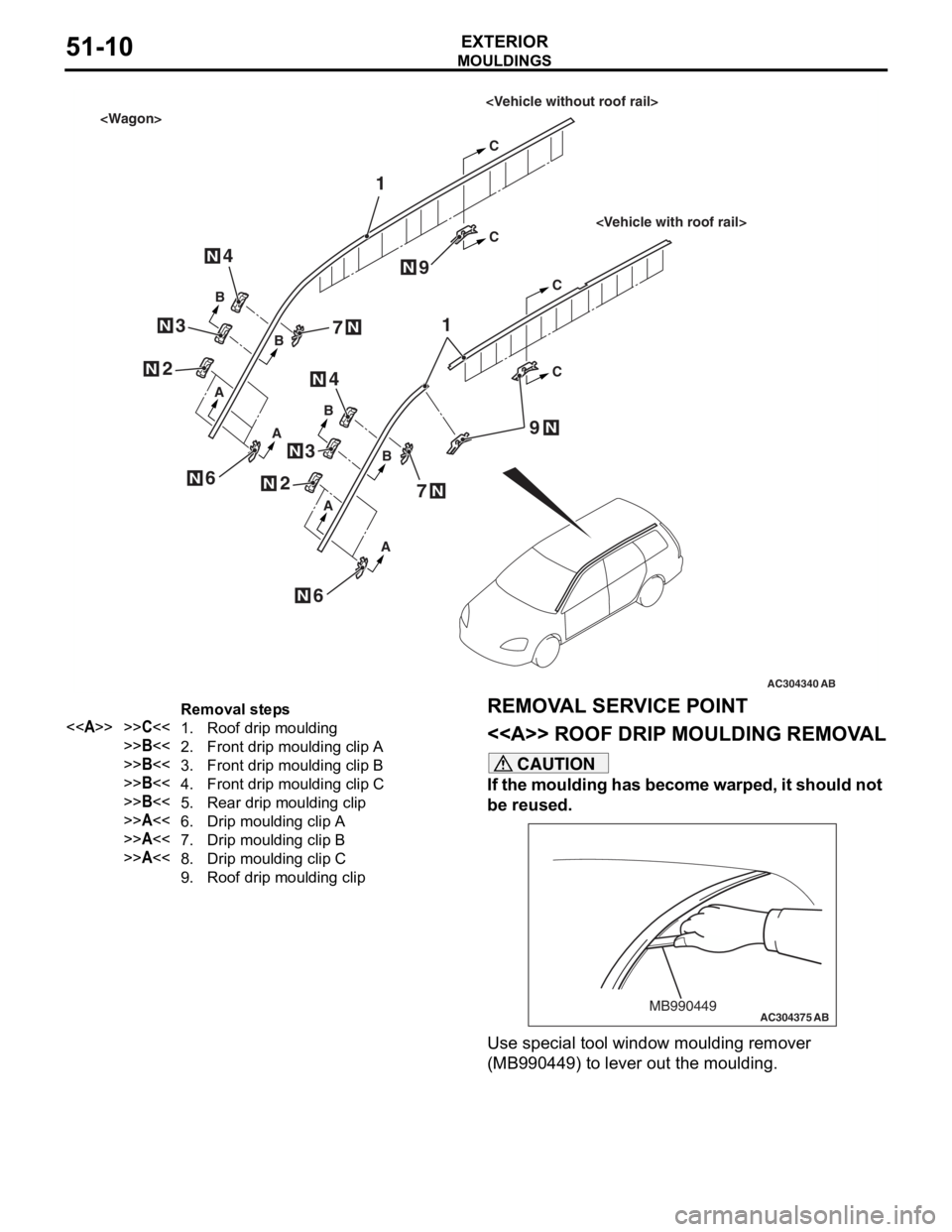
Removal steps
<>>>C<<1.Roof drip moulding
>>B<<2.Front drip moulding clip A
>>B<<3.Front drip moulding clip B
>>B<<4.Front drip moulding clip C
>>B<<5.Rear drip moulding clip
>>A<<6.Drip moulding clip A
>>A<<7.Drip moulding clip B
>>A<<8.Drip moulding clip C
9.Roof drip moulding clip
MO
UL DI N G S
EXTERIOR51-10
REMOVA L SER VICE POINT
<> ROOF DRIP MOULDING REMOV A L
CAUTION
If the moulding has become warped, it should not
be reused.
AC304375MB990449AB
Use special tool window moulding remover
(MB990449) to lever out the moulding.
Page 343 of 800
MOULDINGS
EXTERIOR51-11
INSTALLATION SERVICE POINTS
>>A<< DRIP MOULDING CLIP C/DRIP
MOULDING CLIP B/DRIP MOULDING
CLIP A INSTALLATION
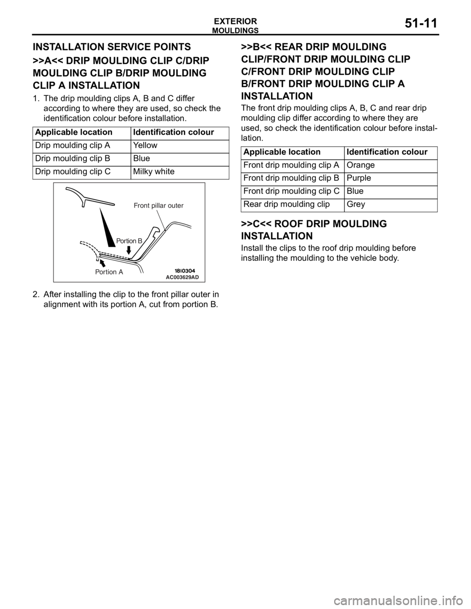
1. The drip moulding clips A, B and C differ according to where they are used, so check the
identification colour before installation.
Applicable locationIdentification colour
Drip moulding clip AYe l l o w
Drip moulding clip BBlue
Drip moulding clip CMilky white
AC003629
Front pillar outer
Portion B
Portion AAD
2. Af ter inst alling the clip to the f r ont pilla r outer in
align m ent with it s portio n A, cu t from portion B.
>>B<< REAR DRIP MOULDING
CLIP/FRONT DRIP MOULDING CLIP
C/FRONT DRIP MOULDING CLIP
B/FRONT DRIP MOULDING CLIP A
INST
ALLA TION
The front drip mou l din g clip s A, B, C an d rear d r ip
moulding
clip dif f er accordin g to where they are
used
, so check th e ide n tification colou r before inst al
-
lation.
Applicable locationIdentification colour
Front drip moulding clip AOrange
Front drip moulding clip BPurple
Front drip moulding clip CBlue
Rear drip moulding clipGrey
>>C<< ROOF DRIP MOULDING
INSTALLA TION
Install the clip s to th e roof d r ip mould i ng before
inst
allin g the moulding to the vehicle body .
Page 344 of 800
AC504986 AC400117
AC400128
Section A – A
DOOR MOULDINGS
Section B – B Section C – C
AB
AA C
C
BB2
1
3
ClipClip
Boss
AC400840AE
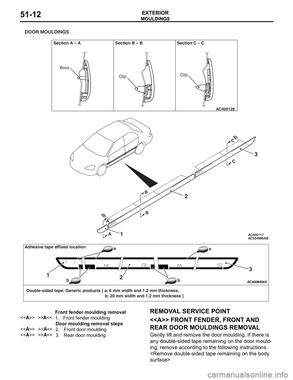
Double-sided tape: Generic products [ a: 6 mm width and 1.2 mm thickness, b: 20 mm width and 1.2 mm thickness ]
12
3
a
b
baAdhesive tape affixed location
Front fender moulding removal
<>>>A<<1.Front fender moulding
Door moulding removal steps
<>>>A<<2.Front door moulding
<>>>A<<3.Rear door moulding
MO
UL DI N G S
EXTERIOR51-12
REMOVA L SER VICE POINT
<> FRONT FENDER, FRONT AND
REAR DOOR MOULDINGS REMOV
A L
Gently lif t and remo ve th e door moulding . If the r e is
any d
ouble-sided t ape remainin g on th e door mould
-
ing, remove accord ing to the fo llowing in struction s .
Page 345 of 800
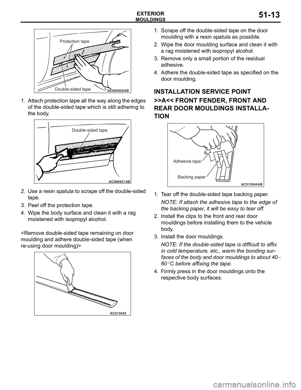
AC000420Double-sided tapeProtection tapeAB
MO
UL DI N G S
EXTERIOR51-13
1.At t a ch pro t ection t a pe all th e wa y alon g the e dge s
of the do uble - sid ed t ape which is still adh ering to
th e body .
AC000421
Double-sided tape
AB
2.Use a resin sp atula to scrape of f t he dou ble-sided
t ape .
3.Pee l of f the pr otect i on t ape .
4.Wipe th e body su rface and clean it with a rag
moistened with isopro p yl alcohol.
and a dhere d ouble-sided t ape (wh en
re-using do
or mo ulding)>
AC313343
1.Scrape o f f the double-sided t ape on th e door
moulding with a re sin sp atula as possible.
2.Wipe th e door moulding surfa c e a nd clean it with
a rag moistened with isoprop yl a l co hol.
3.Remove only a small po rtion o f the re sid ual
a dhesive .
4.Adh e re the double-sided t ape as specified on t he
d oor mo ulding.
INSTALLA T ION SER VICE POINT
>>A<< FRONT FENDER, FRONT AND
REAR DOOR MOULDINGS INST
ALLA
-
TION
AC313344
Backing paper
Adhesive tape
AB
1.
T ear of f the double-sided t ape backing p aper .
NOTE: If atta ch the adhesive t a pe to the edg e of
th
e backing p aper , it will be easy to te ar off.
2.In st all the clip s to the front a nd rear door
mouldings befo r e inst alling th em to the vehicle
b ody .
3.In st all the do or mo uldings.
NOTE: If the double-sided t ape is difficult to af fix
in co
ld te mpera t ure, et c., warm the b ondin g su r
-
faces of the bod y and doo r mo uldin g s to ab out 40−
60
°C bef ore affixing the t a p e .
4.Firmly pre ss in the door moulding s ont o the
re spective bod y surface s .
Page 346 of 800
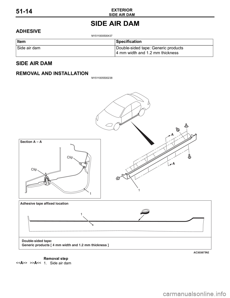
SIDE AIR DAM
EXTERIOR51-14
SIDE AIR DAM
ADHESIVEM1511000500437
ItemSpecification
Side air damDouble-sided tape: Generic products
4 mm width and 1.2 mm thickness
SIDE AIR DAM
REMOVAL AND INSTALLATIONM1511005500238
AC303877
Clip
Clip
Section A – A
AE
1
A
A
Adhesive tape affixed location
Double-sided tape:
Generic products [ 4 mm width and 1.2 mm thickness ] 1
1
Removal step
<>>>A<<1.Side air dam
Page 347 of 800
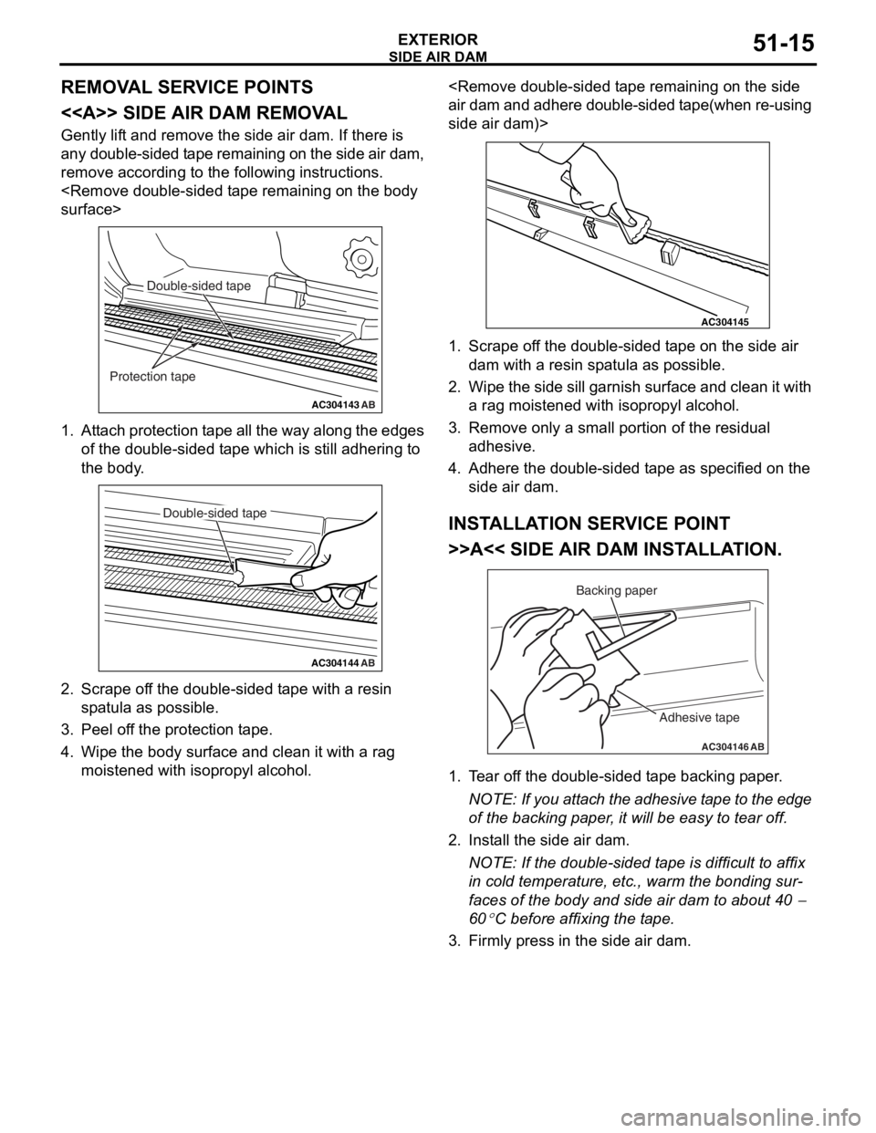
Page 348 of 800
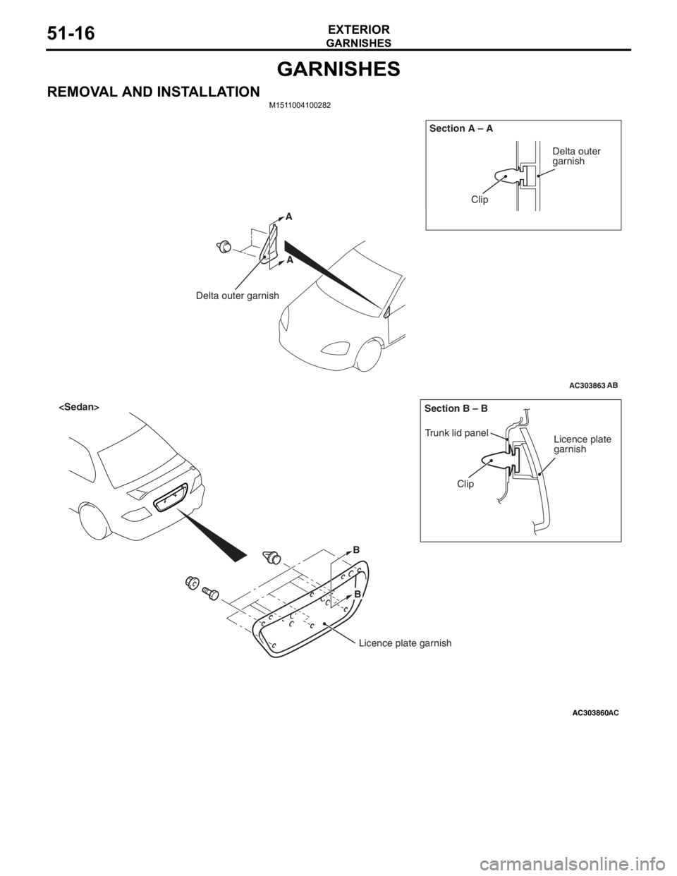
GARNISHES
EXTERIOR51-16
GARNISHES
REMOVAL AND INSTALLATIONM1511004100282
AC303863
Clip
Delta outer garnish Section A – A
AB
Delta outer
garnish
A
A
AC303860
B
Clip
Trunk lid panel
Licence plate
garnish
Section B – B
AC
Licence plate garnish
B
Page 349 of 800

DOOR SASH TAPE
EXTERIOR51-17
DOOR SASH TAPE
SPECIAL TOOLM1511000601664
ToolNumberNameUse
MB990528
MB990528Stripe tape spatulaInstallation of door sash tape
DOOR SASH TA PE
REMOVA L AND INST ALLA TION
Pre-removal and Post-installation Operation
•Door Trim Assembly Removal and Installation (Refer to
GROUP 52A
P.52A-17).
•Door Beltline Weatherstrip Inner Removal and Installation
(Refer to GROUP 42
P.42-39).
•Door Opening Weatherstrip Outer Removal and Installa-
tion (Refer to GROUP 42 P.42-39).
•Door Window Glass Runchannel Removal and Installation
(Refer to GROUP 42
P.42-39).
•Door Beltline Moulding Removal and Installation (Refer to
GROUP 42
P.42-39).
AC404973
124
3
N
NN
N
AC
Removal steps
<>>>A<<1.Front door sash tape upper
<>>>A<<2.Front door sash tape rear
<>>>A<<3.Rear door sash tape upper
<>>>A<<4.Rear door sash tape front
REMOVA L SER VICE POINT
<> DOOR SASH T A PES REMOV A L
CAUTION
Pay attention to keep from getting burned by hot
door panel or tapes.
1. Use a hair drier to warm the tape.
2. Peel the tip of the tape with your finger, and then
peel off the tape parallel to the application
surface.
Page 350 of 800
DOOR SASH TAPE
EXTERIOR51-18
INSTALLATION SERVICE POINT
>>A<< DOOR SASH TAPES INSTALLA-
TION
CAUTION
•The ambient temperature should be 20 to
30
°C. Ensure that the working area is clean.
Ideally, the tape application should be done at
ambient temperature of 25
°C.
•If ambient temperature is less than 15°C, heat
the tape and application surface to a tempera
-
ture of 20 to 30°C. If ambient temperature is
35
°C or higher, cool down them. The adhe-
sive property of the tape is deteriorated at low
temperature, so the tape may come adrift eas
-
ily. Meanwhile, it gets softened at hot temper-
ature.
•When beginning to apply the tape, pay partic-
ular attention. If the end of the tape cannot be
applied to the specified position with an accu
-
racy of less than 1 mm, it may cause the poor
appearance or adhesion.
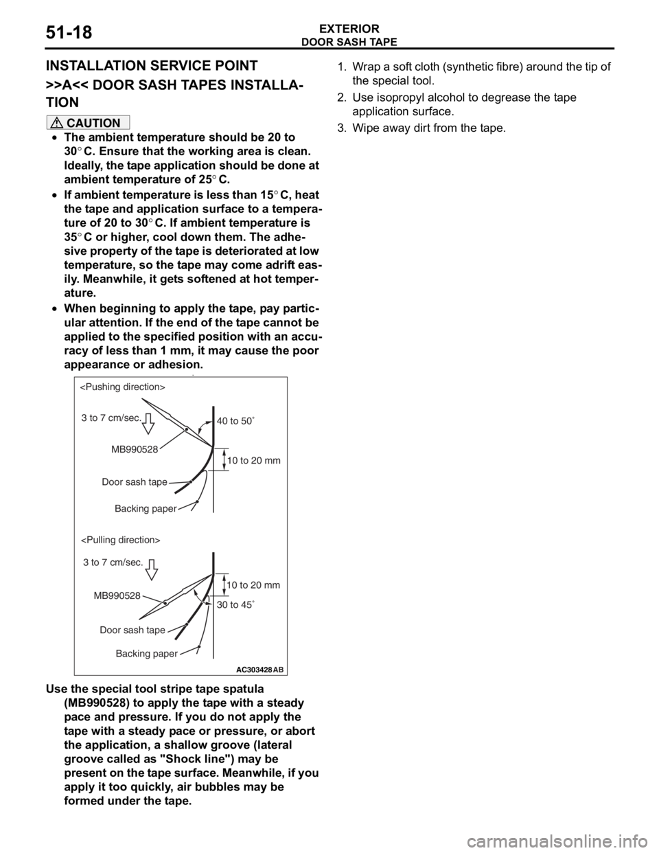
•
AC303428
40 to 50˚
30 to 45˚
10 to 20 mm
10 to 20 mm
AB
MB990528
MB990528 Door sash tapeDoor sash tape
Backing paper
Backing paper
3 to 7 cm/sec.
Use the special tool stripe tape spatula (MB990528) to apply the tape with a steady
pace and pressure. If you do not apply the
tape with a steady pace or pressure, or abort
the application, a shallow groove (lateral
groove called as "Shock line") may be
present on the tape surface. Meanwhile, if you
apply it too quickly, air bubbles may be
formed under the tape.
1. Wrap a soft cloth (synthetic fibre) around the tip of
the special tool.
2. Use isopropyl alcohol to degrease the tape application surface.
3. Wipe away dirt from the tape.