Bumper MITSUBISHI LANCER IX 2006 Service Manual
[x] Cancel search | Manufacturer: MITSUBISHI, Model Year: 2006, Model line: LANCER IX, Model: MITSUBISHI LANCER IX 2006Pages: 800, PDF Size: 45.03 MB
Page 275 of 800
HOOD
BODY42-3
HOOD
ON-VEHICLE SERVICE
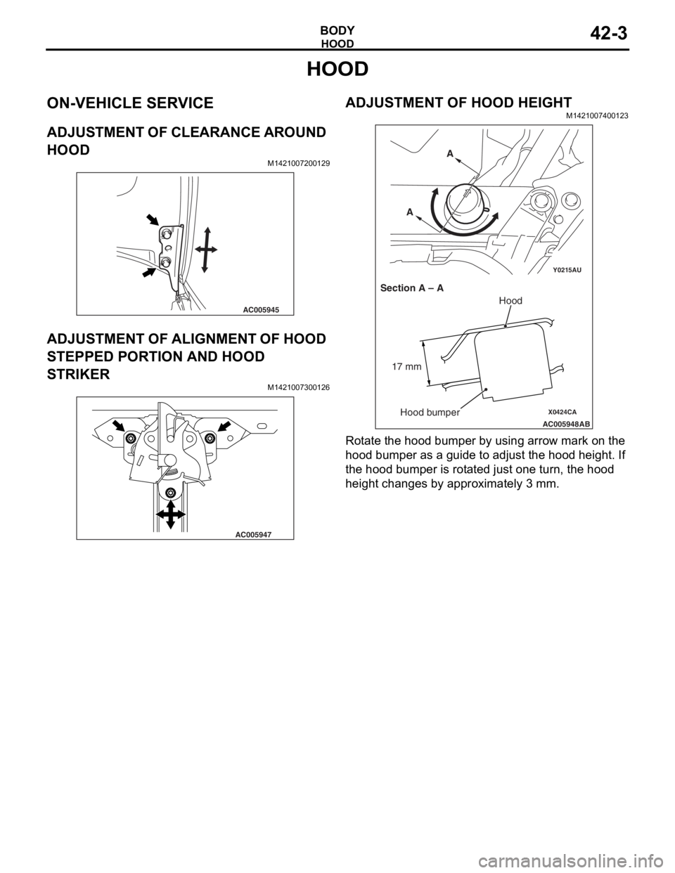
ADJUSTMENT OF CLEARANCE AROUND
HOOD
M1421007200129
AC005945
ADJUSTMENT OF ALIGNMENT OF HOOD
STEPPED PORTION AND HOOD
STRIKER
M14210073 0012 6
AC005947
ADJUSTMENT OF HOOD HEIGHT
M14210074 0012 3
Y0215AU
X0424CA
AC005948
AB
Section A – A A
A
Hood
Hood bumper
17 mm
Ro
t a te t he hood bu mper by using arrow mark o n the
hood bu
mpe r as a g u ide t o adju s t the hood h e ight . If
the hoo
d bumper is rot a te d just one turn, th e hood
heigh
t cha nges by approximately 3 mm.
Page 276 of 800
HOOD
BODY42-4
HOOD
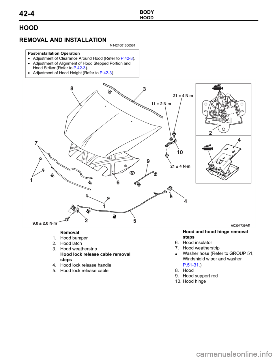
REMOVAL AND INSTALLATION
M1421001600561
Post-installation Operation
•Adjustment of Clearance Around Hood (Refer to P.42-3).
•Adjustment of Alignment of Hood Stepped Portion and
Hood Striker (Refer to
P.42-3).
•Adjustment of Hood Height (Refer to P.42-3).
AC304739
1
1
2 2
4 4
5
6
7 3
8
910
AD9.0 ± 2.0 N·m 21 ± 4 N·m
11 ± 2 N·m
21 ± 4 N·m
Removal
1.Hood bumper
2.Hood latch
3.Hood weatherstrip
Hood lock release cable removal
steps
4.Hood lock release handle
5.Hood lock release cable
Hood and hood hinge removal
steps
6.Hood insulator
7.Hood weatherstrip
•Washer hose (Refer to GROUP 51,
Windshield wiper and washer
P.51-31.)
8.Hood
9.Hood support rod
10.Hood hinge
Page 278 of 800
FENDER
BODY42-6
FENDER
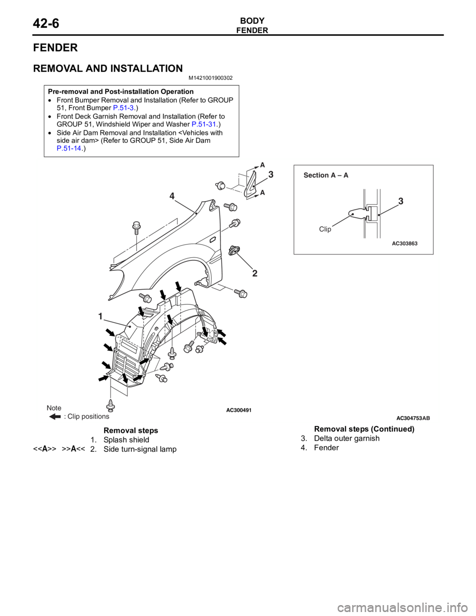
REMOVAL AND INSTALLATION
M1421001900302
Pre-removal and Post-installation Operation
•Front Bumper Removal and Installation (Refer to GROUP
51, Front Bumper P.51-3.)
•Front Deck Garnish Removal and Installation (Refer to
GROUP 51, Windshield Wiper and Washer P.51-31.)
•Side Air Dam Removal and Installation
P.51-14.)
AC300491AC304753
AC303863
Clip
Section A – A
AB
A A
1
23
3
4
Note
: Clip positions
Removal steps
1.Splash shield
<>>>A<<2.Side turn-signal lamp
3.Delta outer garnish
4.Fender
Removal steps (Continued)
Page 313 of 800
Page 314 of 800
TRUNK LID
BODY42-42
3. If there is a difference in height between the side outer panels and the side edges of the trunk lid
panel assembly, check the trunk lid hinges and, if
necessary, replace them
4. If the clearance around the trunk lid panel assembly is not uniform, and the trunk lid can be
locked and unlocked smoothly, make adjustments
to the trunk lid bumpers (refer to
P.42-42) and
trunk lid hinges (Refer to P.42-42).
5. If the locking and unlocking of the trunk lid still is difficult after making the above adjustments,
adjust the trunk lid striker (Refer to
P.42-42).
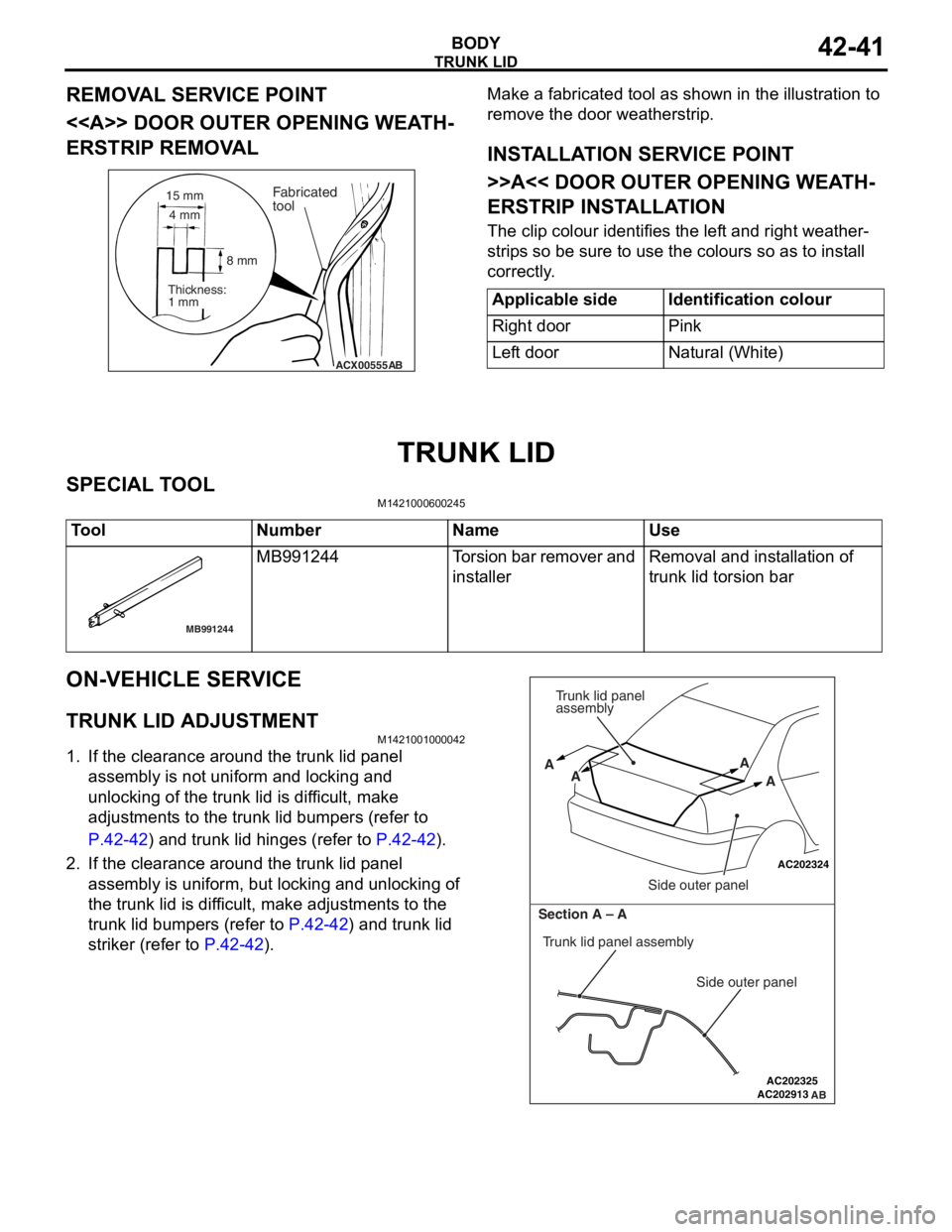
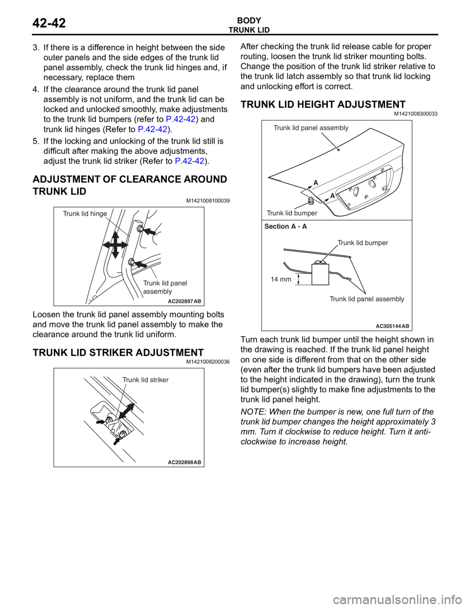
ADJUSTMENT OF CLEARANCE AROUND
TRUNK LID
M1421008100039
AC202897
Trunk lid panel
assembly
Trunk lid hinge
AB
Loosen the trunk lid p a nel a sse mbly mounting bolt s
and move
the trun k lid p anel assembly to make t he
clea
rance aroun d the t r unk lid u n iform.
TRUNK LID STRIKER ADJUSTMENT
M14210082 0003 6
AC202898
Trunk lid striker
AB
After checking the trunk lid relea s e cable for pro per
routin
g, lo osen the trun k lid striker mo untin g bolt s .
Ch
ange th e position of t he trunk lid st rike r relat i ve to
the trun
k lid la tch a s sembly so tha t trunk lid lockin g
and un
lockin g ef f o rt is corre ct.
TRUNK LID HEIGHT ADJUSTMENT
M14210083 0003 3
AC305144
Section A - A
Trunk lid bumper
Trunk lid panel assembly
A
A
Trunk lid bumper Trunk lid panel assembly
AB
14 mm
T
u rn each trun k lid bumper u n til the he ight shown in
the dra
w ing is reached. If the t r unk lid p a n e l he ight
on one
sid e is dif f erent from that on the oth e r side
(even
a f t e r th e t r un k lid bu mp ers have be en ad ju st ed
to the h
e igh t ind i ca ted in the dra w ing), tu rn the trunk
lid bumper(s)
slight ly to make fine adjustment s to the
trunk lid p
a nel h e ight .
NOTE: Whe n the b u mpe r is new , one full turn o f the
trunk lid bumper ch anges t he height appro x imately 3
mm.
T
u
rn it clockwise to r educe height. T u rn it anti
-
clockwise to increase height.
Page 315 of 800
TRUNK LID
BODY42-43
TRUNK LID
REMOVAL AND INSTALLATION
M1421002200180
AC301676
Y0636AU
Y0637AU
AB
8.9 ± 1.9 N·m
A
AB
B 15 mm
14 mm
Section A - A
Section B - B
9
5
6
4
12
9
59
7
11
10
8 3 5 1
2
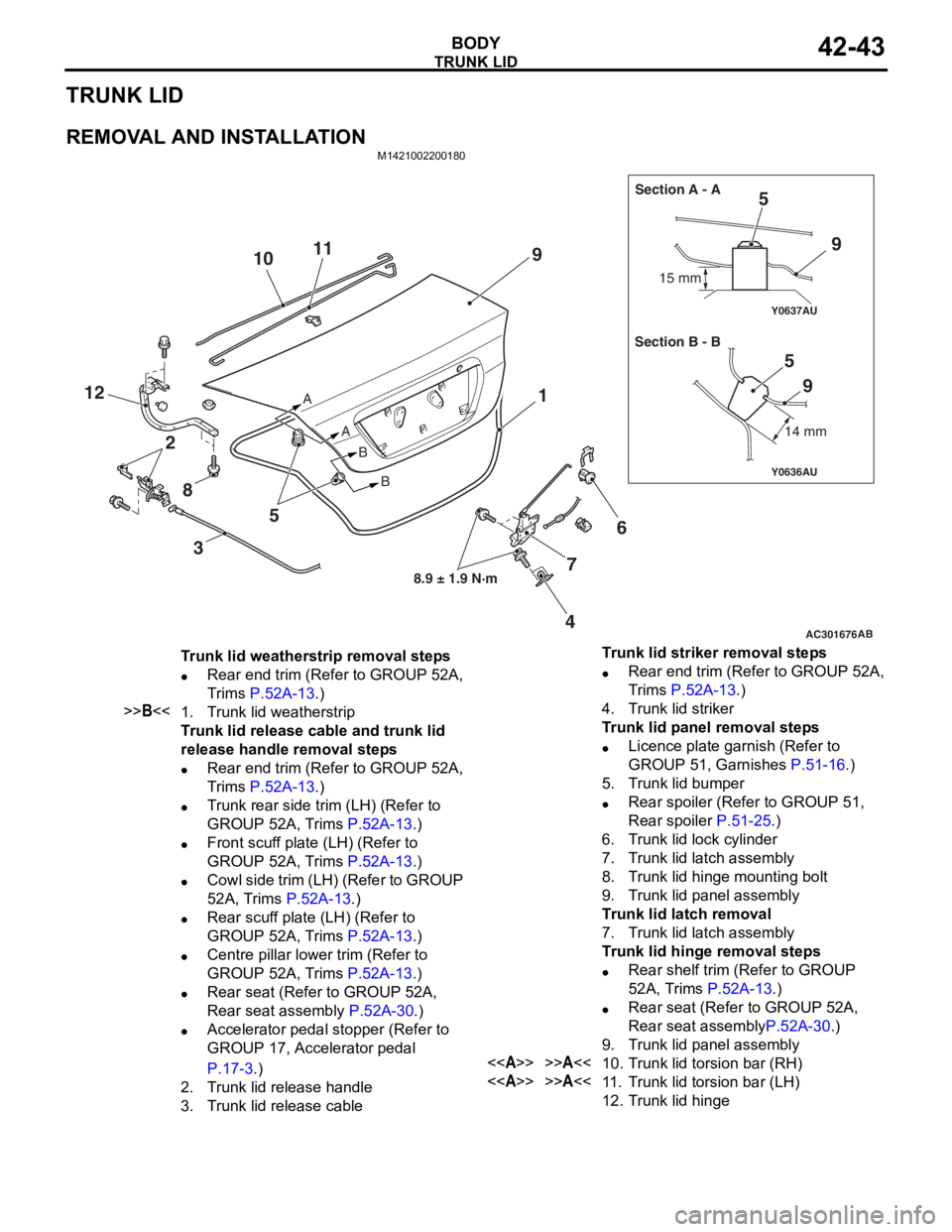
Trunk lid weatherstrip removal steps
•Rear end trim (Refer to GROUP 52A,
Trims
P.52A-13.)
>>B<<1.Trunk lid weatherstrip
Trunk lid release cable and trunk lid
release handle removal steps
•Rear end trim (Refer to GROUP 52A,
Trims
P.52A-13.)
•Trunk rear side trim (LH) (Refer to
GROUP 52A, Trims
P.52A-13.)
•Front scuff plate (LH) (Refer to
GROUP 52A, Trims
P.52A-13.)
•Cowl side trim (LH) (Refer to GROUP
52A, Trims
P.52A-13.)
•Rear scuff plate (LH) (Refer to
GROUP 52A, Trims
P.52A-13.)
•Centre pillar lower trim (Refer to
GROUP 52A, Trims
P.52A-13.)
•Rear seat (Refer to GROUP 52A,
Rear seat assembly
P.52A-30.)
•Accelerator pedal stopper (Refer to
GROUP 17, Accelerator pedal
P.17-3.)
2.Trunk lid release handle
3.Trunk lid release cable
Trunk lid striker removal steps
•Rear end trim (Refer to GROUP 52A,
Trims
P.52A-13.)
4.Trunk lid striker
Trunk lid panel removal steps
•Licence plate garnish (Refer to
GROUP 51, Garnishes
P.51-16.)
5.Trunk lid bumper
•Rear spoiler (Refer to GROUP 51,
Rear spoiler
P.51-25.)
6.Trunk lid lock cylinder
7.Trunk lid latch assembly
8.Trunk lid hinge mounting bolt
9.Trunk lid panel assembly
Trunk lid latch removal
7.Trunk lid latch assembly
Trunk lid hinge removal steps
•Rear shelf trim (Refer to GROUP
52A, Trims
P.52A-13.)
•Rear seat (Refer to GROUP 52A,
Rear seat assembly
P.52A-30.)
9.Trunk lid panel assembly
<>>>A<<10.Trunk lid torsion bar (RH)
<>>>A<<11 .Trunk lid torsion bar (LH)
12.Trunk lid hinge
Page 321 of 800
AC305322
Adhesive: 3M ATD Part No.8531 Heavy drip check sealer, 3M ATD Part No.8646 Automotive joint and seam sealer
or equivalent
AB
7
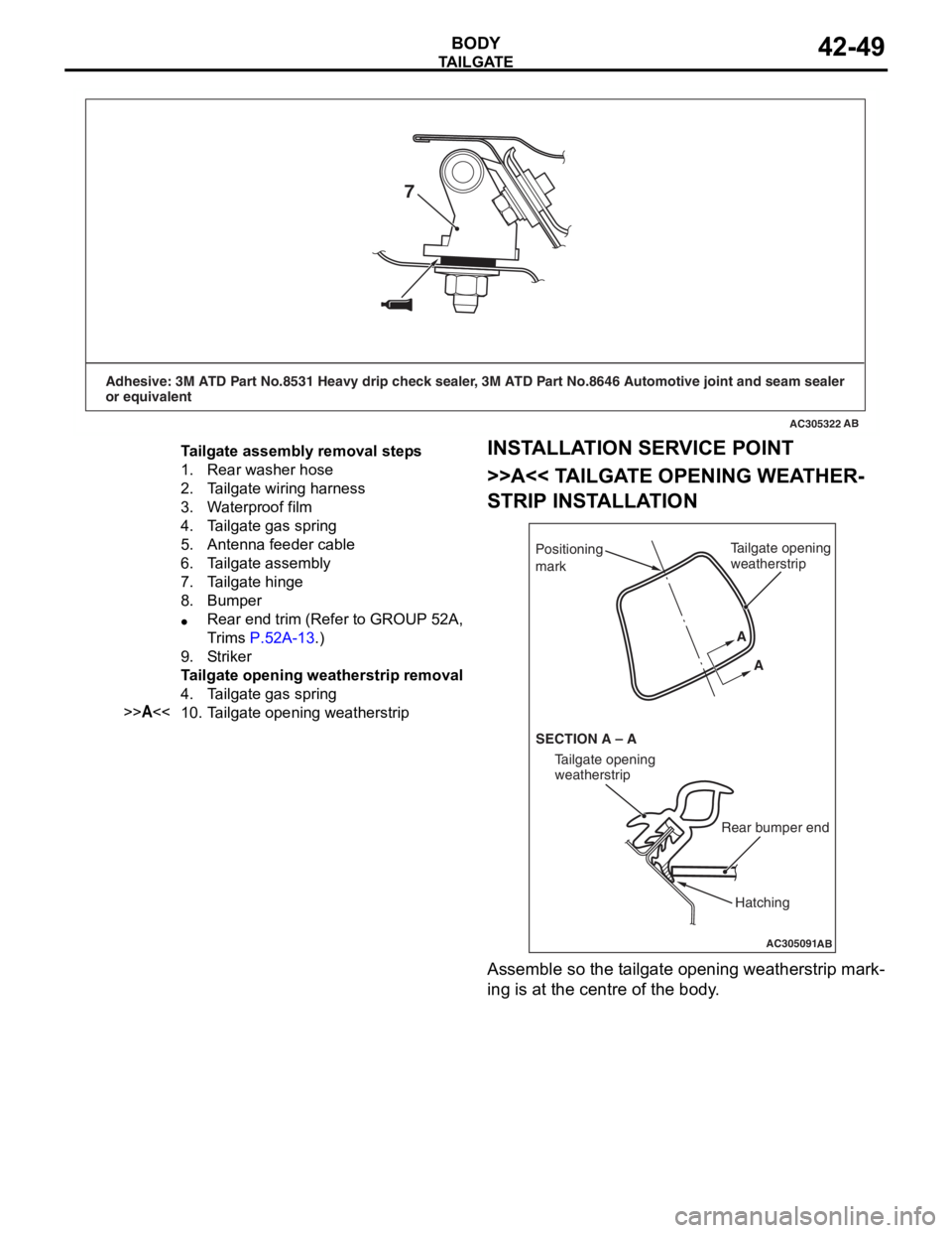
Tailgate assembly removal steps
1.Rear washer hose
2.Tailgate wiring harness
3.Waterproof film
4.Tailgate gas spring
5.Antenna feeder cable
6.Tailgate assembly
7.Tailgate hinge
8.Bumper
•Rear end trim (Refer to GROUP 52A,
Trims
P.52A-13.)
9.Strik er
Tailgate opening weatherstrip removal
4.Tailgate gas spring
>>A<<10.Tailgate opening weatherstrip
TA ILGA TE
BOD Y42-49
INSTALLA T ION SER VICE POINT
>>A<< TA ILGA TE OPENING WEA T HER-
STRIP INSTALLA TION
AC305091
Positioning
mark
AB
Tailgate opening
weatherstrip
Rear bumper end
Tailgate opening
weatherstrip
SECTION A – A A
A
Hatching
Assemble so the t a ilgate o penin g weathe rstrip mark-
ing is at the centre o f the b ody .
Page 333 of 800

51-1
GROUP 51
EXTERIOR
CONTENTS
FRONT BUMPER ASSEMBLY . . . . .51-3
ADHESIVE . . . . . . . . . . . . . . . . . . . . . . . . . 51-3
FRONT BUMPER ASSEMBLY . . . . . . . . . . 51-3
REMOVAL AND INSTALLATION . . . . . . . . 51-3
DISASSEMBLY AND REASSEMBLY . . . . . 51-4
REAR BUMPER ASSEMBLY . . . . . .51-6
REMOVAL AND INSTALLATION . . . . . . . . 51-6
DISASSEMBLY AND REASSEMBLY . . . . . 51-7
MOULDINGS . . . . . . . . . . . . . . . . . . .51-8
SPECIAL TOOL . . . . . . . . . . . . . . . . . . . . . 51-8
ADHESIVE . . . . . . . . . . . . . . . . . . . . . . . . . 51-9
MOULDINGS . . . . . . . . . . . . . . . . . . . . . . . 51-9
REMOVAL AND INSTALLATION . . . . . . . . 51-9
SIDE AIR DAM . . . . . . . . . . . . . . . . . .51-14
ADHESIVE . . . . . . . . . . . . . . . . . . . . . . . . . 51-14
SIDE AIR DAM . . . . . . . . . . . . . . . . . . . . . . 51-14
REMOVAL AND INSTALLATION . . . . . . . . 51-14
GARNISHES . . . . . . . . . . . . . . . . . . .51-16
REMOVAL AND INSTALLATION . . . . . . . . 51-16
DOOR SASH TAPE . . . . . . . . . . . . . .51-17
SPECIAL TOOL . . . . . . . . . . . . . . . . . . . . . 51-17
DOOR SASH TAPE . . . . . . . . . . . . . . . . . . 51-17
REMOVAL AND INSTALLATION
REMOVAL AND INSTALLATION
REAR SPOILER
REMOVAL AND INSTALLATION . . . . . . . . 51-25
TAILGATE SPOILER
REMOVAL AND INSTALLATION . . . . . . . . 51-26
ROOF RAIL
REMOVAL AND INSTALLATION . . . . . . . . 51-27
WINDSHIELD WIPER AND
WASHER. . . . . . . . . . . . . . . . . . . . . . .51-28
GENERAL INFORMATION . . . . . . . . . . . . . 51-28
SERVICE SPECIFICATION . . . . . . . . . . . . 51-28
SPECIAL TOOLS . . . . . . . . . . . . . . . . . . . . 51-29
TROUBLESHOOTING . . . . . . . . . . . . . . . . 51-30
ON-VEHICLE SERVICE . . . . . . . . . . . . . . . 51-30
WINDSHIELD WIPER AND WASHER . . . . 51-31
REMOVAL AND INSTALLATION . . . . . . . . 51-31
INSPECTION. . . . . . . . . . . . . . . . . . . . . . . . 51-33
REAR WIPER AND WASHER
GENERAL INFORMATION . . . . . . . . . . . . . 51-35
SERVICE SPECIFICATION . . . . . . . . . . . . 51-35
TROUBLESHOOTING . . . . . . . . . . . . . . . . 51-36
ON-VEHICLE SERVICE . . . . . . . . . . . . . . . 51-36
REAR WIPER AND WASHER . . . . . . . . . . 51-36
REMOVAL AND INSTALLATION . . . . . . . . 51-36
INSPECTION. . . . . . . . . . . . . . . . . . . . . . . . 51-37
Continued on next page
Page 335 of 800
FRONT BUMPER ASSEMBLY
EXTERIOR51-3
FRONT BUMPER ASSEMBLY
ADHESIVEM1511000501195
ItemSpecification
Front three-diamond markDouble-sided tape: Generic products
0.8 mm thickness
FRONT BUMPER ASSEMBLY
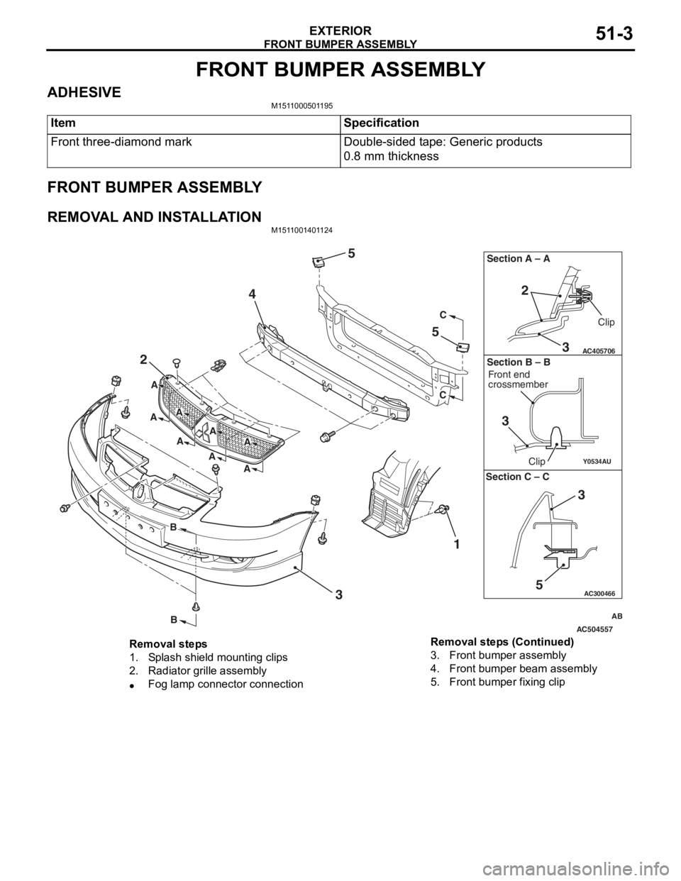
REMOVAL AND INSTALLATIONM1511001401124
AC504557
AC300466
Y0534AU
AC405706
AB
2
4
5
5
3 1
C
C
B
B
A
A
A
AA
A
A
A
3
2
Section A – A
3
Clip
Front end
crossmember
Clip
Section B – B
5
3
Section C – C
Removal steps
1.Splash shield mounting clips
2.Radiator grille assembly
•Fog lamp connector connection
3.Front bumper assembly
4.Front bumper beam assembly
5.Front bumper fixing clip
Removal steps (Continued)
Page 336 of 800
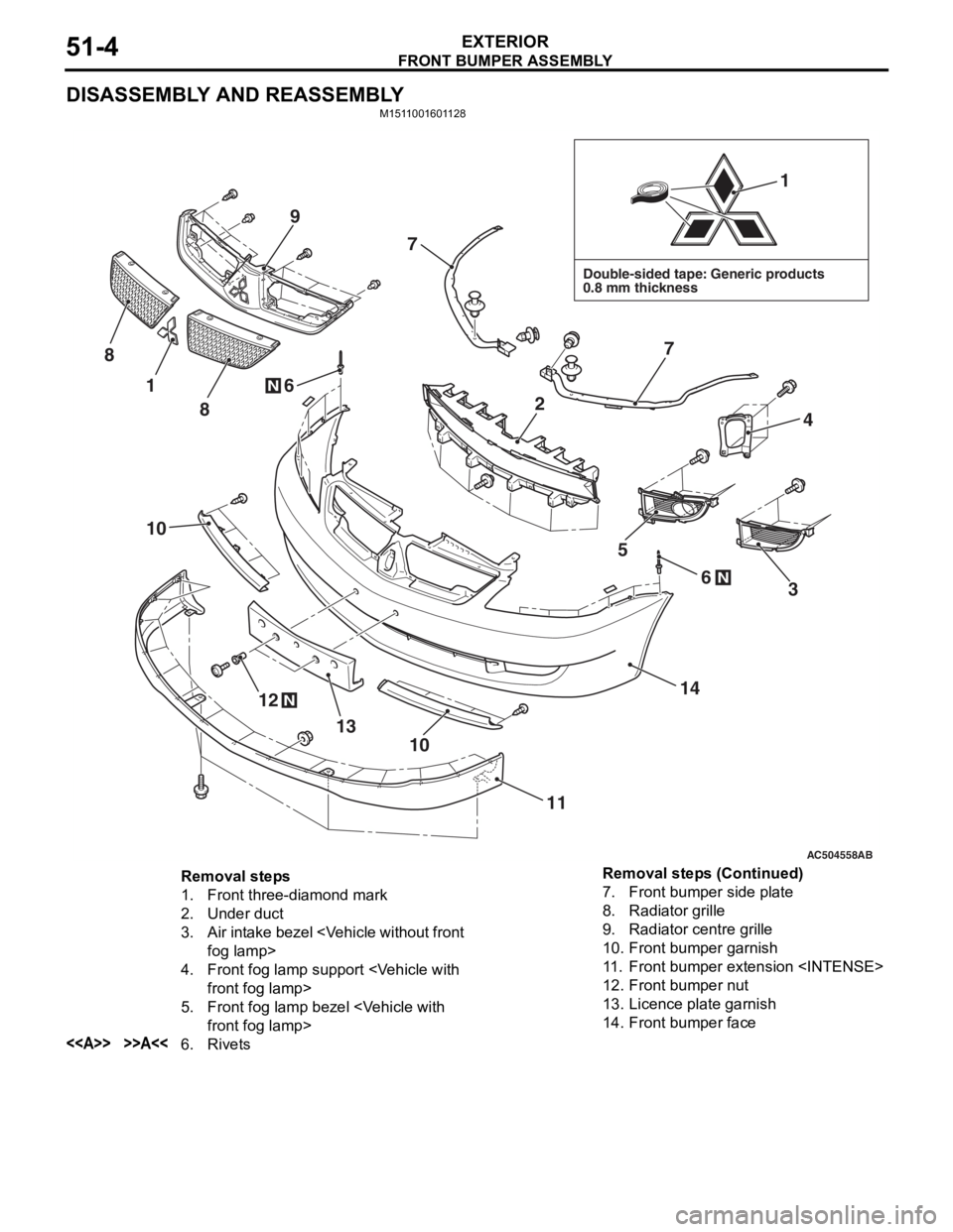
FRONT BUMPER ASSEMBLY
EXTERIOR51-4
DISASSEMBLY AND REASSEMBLY
M1511001601128
AC504558AB
Double-sided tape: Generic products
0.8 mm thickness
1
1
12
13
14
11
10
10
4
7
7
6
6
8
9
8
5
3N
N
N
2
Removal steps
1.Front three-diamond mark
2.Under duct
3.Air intake bezel
4.Front fog lamp sup port
5.Front fog lamp bezel
<>>>A<<6.Rivets
7.Front bumper side plate
8.Radiator grille
9.Radiator centre grille
10.Front bumper garnish
11 .Front bumper extension
12.Front bumper nut
13.Licence plate garnish
14.Front bumper face
Removal steps (Continued)