light MITSUBISHI MONTERO 1987 1.G Workshop Manual
[x] Cancel search | Manufacturer: MITSUBISHI, Model Year: 1987, Model line: MONTERO, Model: MITSUBISHI MONTERO 1987 1.GPages: 284, PDF Size: 14.74 MB
Page 188 of 284
8468 WIPER AND WASHERS SYSTEM - Circuit Diagram
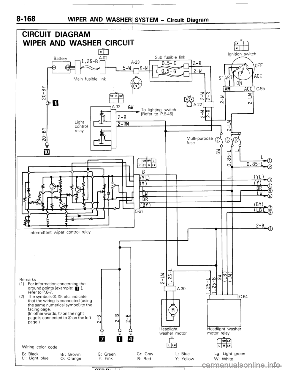
CIRCUIT DIAGRAM
WIPER AND WASHER CIRCU
Ignition switch
lattery
-1.SBAz2 Sub fusible link
A-23
0.5-G
1 5-w m5-w
U
2-R
Z-W
Main fusible link A IL
J.
c
7
C
-
-
-
-
-
-
J A
:
II,
L
.
> 0.85-L '
Light
control
relay P I? 1 -RW ,
Multi-purpose @
fuse
2-B 9
I--
Intermittent wiper control relay
-r ,m:
JJ-
-.
1 C-64
Headlight washer
motor relay Remarks
(I) For information concernina the
ground points (example: a ),
refer to P.8-7.
(2) The svmbols 0.0. etc. indicate
that the wiring is connected (using
the same numerical symbol) to the
facing page.
(In other words, 0 on the right
page is connected to 0 on the left
page.)
a
c: m LB
EEEI L B L1 Wiring color code
B: Black
Br: Brown
LI: Light blue 0: Orange G: Green
P: Pink Gr: Gray
R: Red L: Blue
Y: Yellow Lg: Light green
W: White
/ STB Revision
Page 189 of 284

WIPER AND WASHER SYSTEM - Circuit Diagram 8469
m Column switch -- Front-koer switch -1
Rear wiper and
washer switch
r I Headlight
washer
switch
o-(YL)
@JYJ
(+ BR
@- Lw
L B-l 2
w2-B
! )
1
L
(
7 A-14
1 B-07
81
M
A-58
>
1
GE&washer I
Rear wiper Front washer
motor Front wiper
motor motor
motor
37W124
/ STB Revision
Page 191 of 284
WIPER AND WASHER SYSTEM - Windshield Wipers 8-171
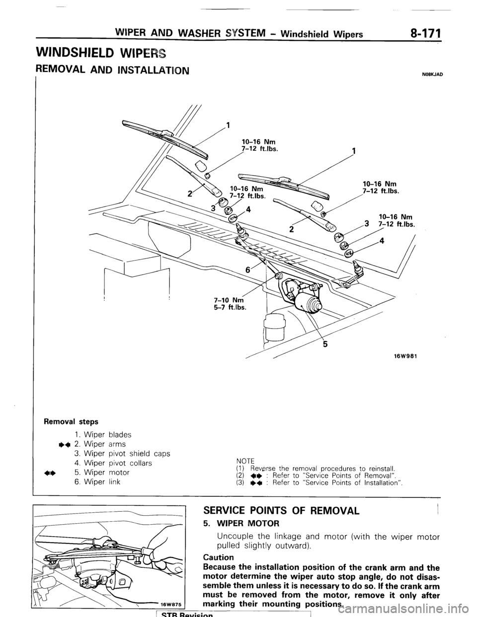
WINDSHIELD WIPE
REMOVAL AND INSTALLATION NOBKJAD
16W961
Removal steps
1. Wiper blades l
+ 2. Wiper arms
3. Wiper pivot shield caps
4. Wiber pivot collars NOTE
4* 5. Wiper motor (1) Reverse the removal procedures to reinstall.
6. Wiper link (2) 4* : Refer to “Service Points of Removal”.
(3) I)* : Refer to “Service Points of Installation”
SERVICE POINTS OF REMOVAL
5. WIPER MOTOR
Uncouple the linkage and motor (with the wiper motor
pulled slightly outward).
Caution
Because the installation position of the crank arm and the
motor determine the wiper auto stop angle, do not disas-
semble them unless it is necessary to do so. If the crank arm
must be removed from the motor, remove it only after
marking their mounting positions.
svision
I
Page 194 of 284
a-174 WIPER AND WASHER $YSTEM - Windshield Wipers / Rear Wiper
REAR WIPtER
7
-est light
16K1920
t
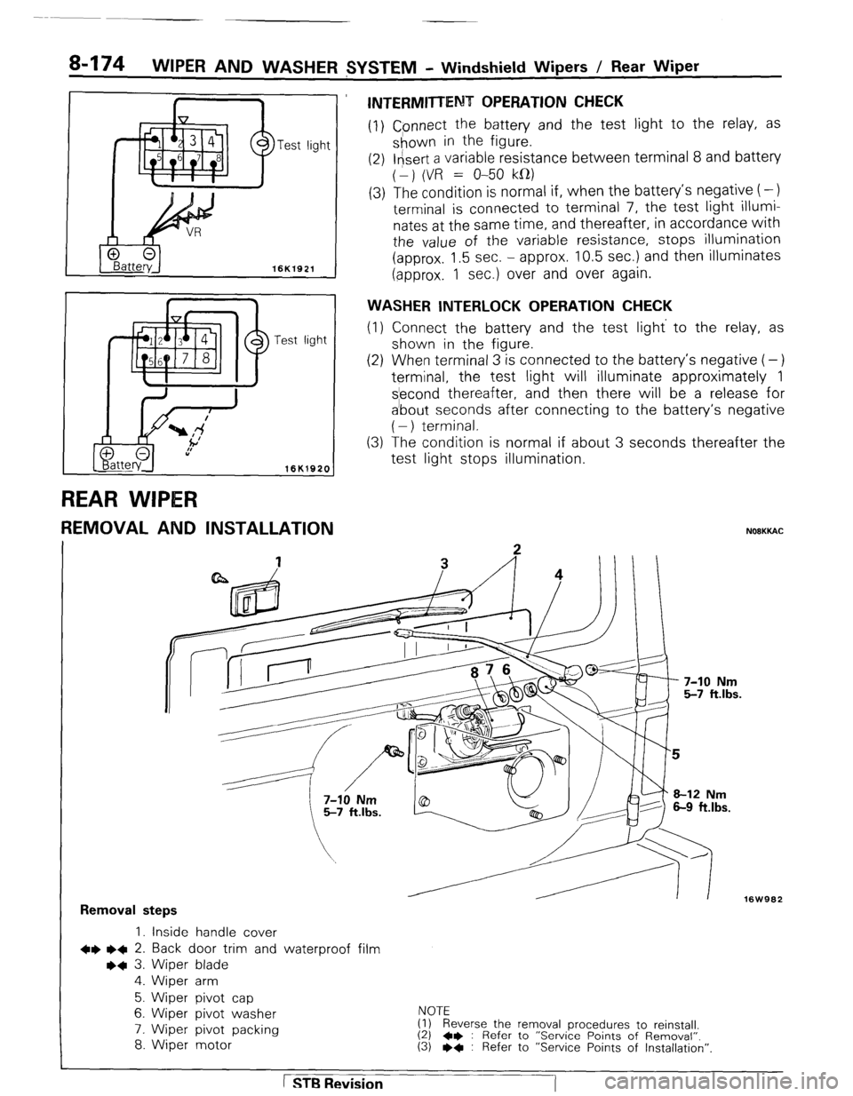
REMOVAL AND INSTALLATION
INTERMITTENT OPERATION CHECK
(1) Cpnnect the battery and the test light to the relay, as
shown in the figure.
(2) l&ert a variable resistance between terminal 8 and battery
(1) (VR = O-50 kfl)
(3) The condition is normal if, when the battery’s negative (-)
terminal is connected to terminal 7, the test light illumi-
nates at the same time, and thereafter, in accordance with
the value of the variable resistance, stops illumination
(approx. 1.5 sec. - approx. 10.5 sec.) and then illuminates
(approx. 1 sec.) over and over again.
WASHER INTERLOCK OPERATION CHECK
(1) Connect the battery and the test light’ to the relay, as
shown in the .figure.
(2) When terminal 3 is connected to the battery’s negative (-)
terminal, the test light will illuminate approximately 1
s’econd thereafter, and then there will be a release for
a’bout seconds after connecting to the battery’s negative
( - ) terminal.
The condition is normal if about 3 seconds thereafter the
test light stops illumination. (3
NOOKKAC
16W962
Removal steps
1. inside handle cover
+e l + 2. Back door trim and waterproof film
++ 3. Wiper blade
4. Wiper arm
5. Wiper pivot cap
6. Wiper pivot washer
7. Wiper pivot packing
8. Wiper motor NOTE
(1) Reverse the removal procedures to reinstall.
(2) 4* : Refer to “Service Points of Removal”. (3) l * : Refer to “Service Points of Installation”.
1 STB Revision
-7
Page 199 of 284
I 1
+ -
li.if 1
2
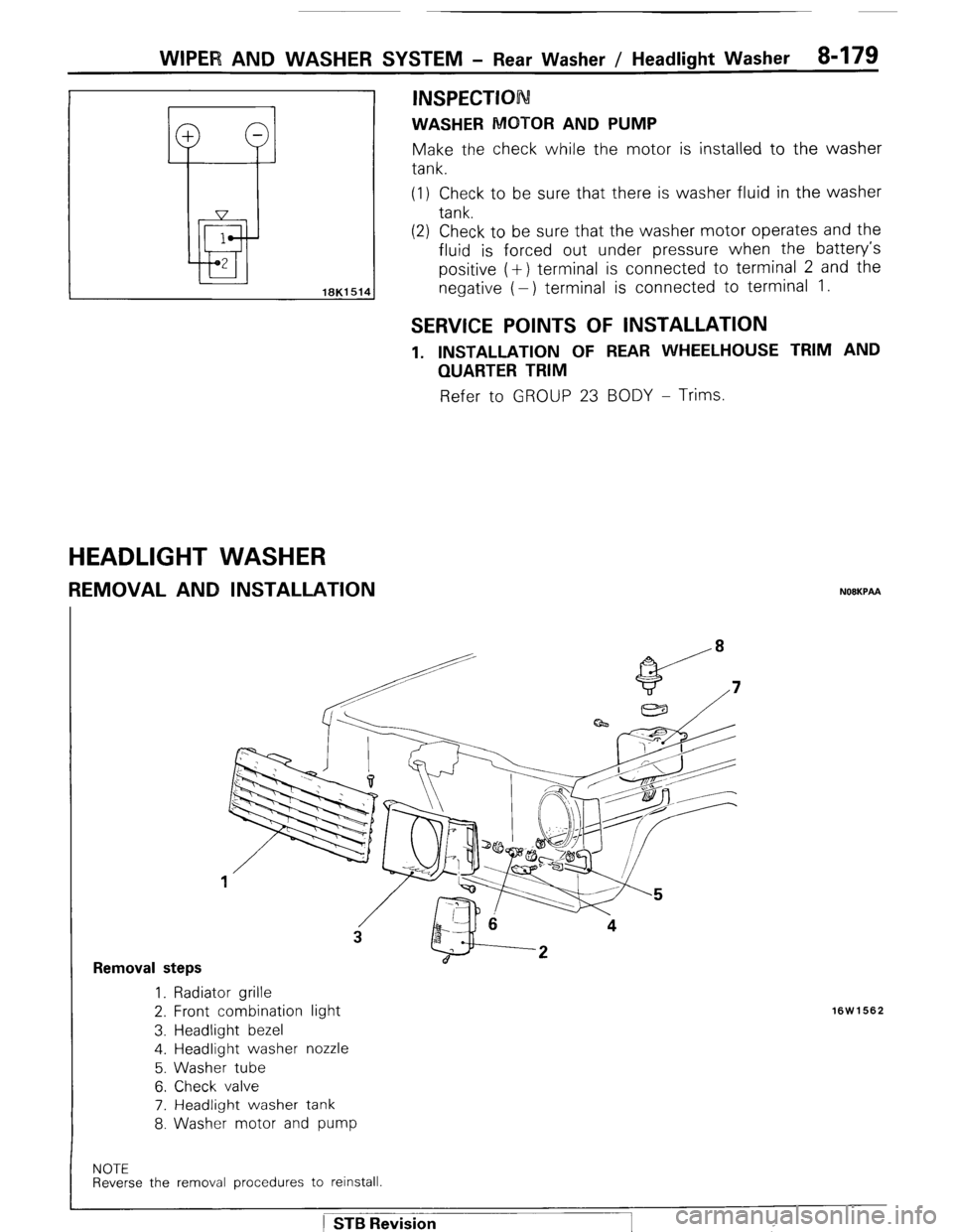
WIPER AND WASHER SYSTEM - Rear Washer / Headlight Washer 8-179 (1) Check to be sure that there is washer fluid in the washer
tank.
(2) Check to be sure that the washer motor operates and the
fluid is forced out under pressure when the battery’s
positive (+) terminal is connected to terminal 2 and the
negative (-) terminal is connected to terminal 1.
INSPECTION
WASHER MOTOR AND PUMP Make the check while the motor is installed to the washer
tank.
SERVICE POINTS OF INSTALLATION
1. INSTALLATION OF REAR WHEELHOUSE TRIM AND
QUARTER TRIM Refer to GROUP 23 BODY - Trims.
HEADLIGHT WASHER
REMOVAL AND INSTALLATION NOEKPAA
Removal steps 1. Radiator grille
2. Front combination light
3. Headlight bezel
4. Headlight washer nozzle
5. Washer tube
6. Check valve
7. Headlight washer tank
8. Washer motor and pump
16W1562
NOTE Reverse the removal procedures to reinstall.
) STB Revision
Page 200 of 284
WIPER AND WASHER SYSTEM - Headlight Washer
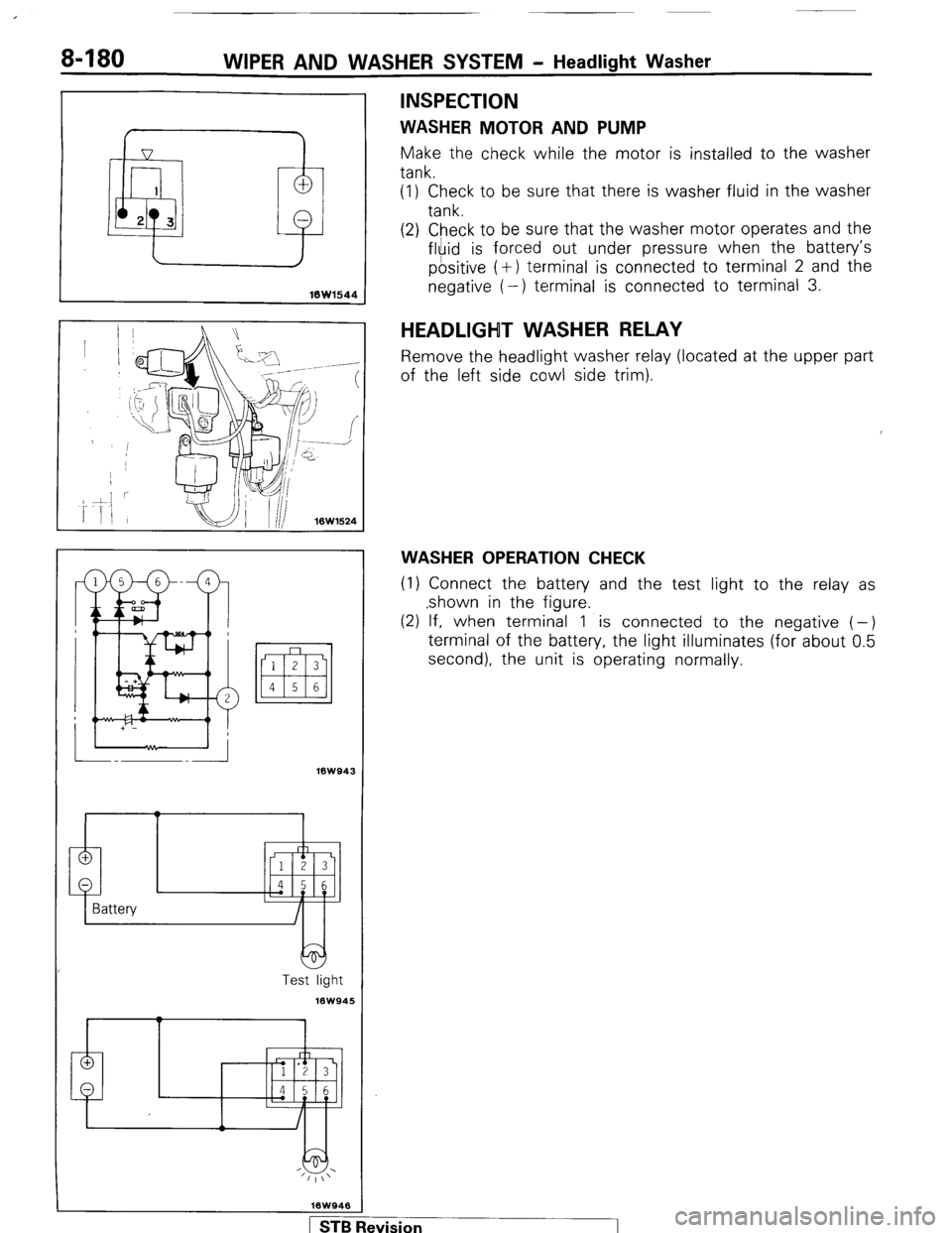
INSPECTION
WASHER MOTOR AND PUMP
Make the check while the motor is installed to the washer
tank.
(1) Check to be sure that there is washer fluid in the washer
tank.
16Wl544
(2) Check to be sure that the washer motor operates and the
fluid is forced out under pressure when the battery’s
positive (+) terminal is connected to terminal 2 and the
negative (-) terminal is connected to terminal 3.
18W943
Test light
16W945
HEADLIGHT WASHER RELAY
Remove the headlight washer relay (located a
of the left side cowl side trim). It the upper part
WASHER OPERATION CHECK
(1) Connect the battery and the test light to the relay as
,shown in the figure.
(2) If, when terminal 1 is connected to the negative (-)
terminal of the battery, the light illuminates (for about 0.5
second), the unit is operating normally.
1 STB Revision -1
Page 202 of 284
8482 WIPER AND WASHER SYSTEM - Column Switch
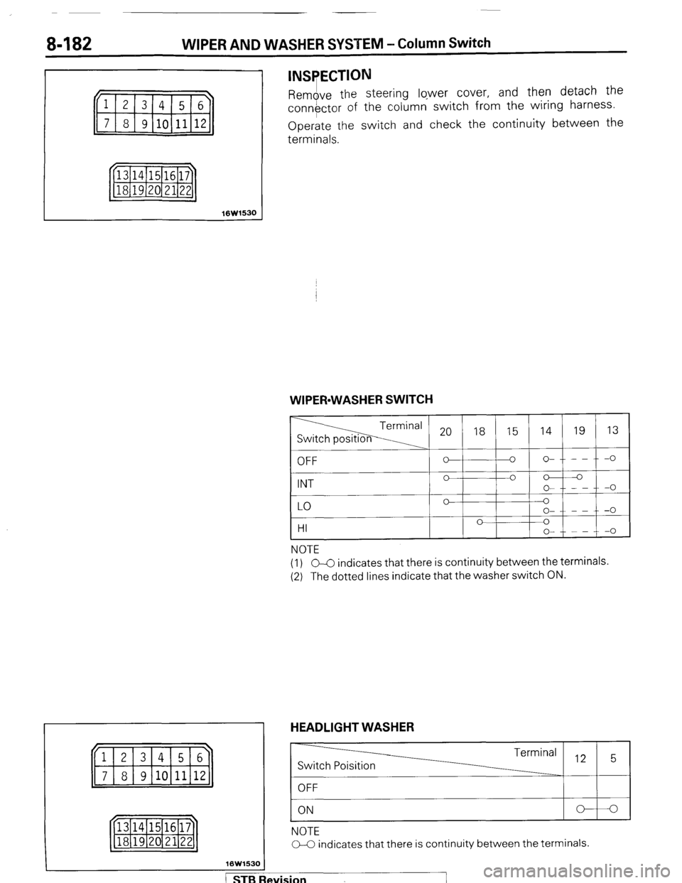
INSPECTION
Remove the steering lqwer cover, and the! detach the
conn#ctor of the c:olumn switch from the wlnng harness.
Operate the switch and check the continuity between the
terminals.
16W1530 WIPER-WASHER SWITCH
16W153C
20 18 15 14 19 13 1 OFF
I - I o-t--t-o I
Ip-I’
’ ’ -
HI v 1 v
o- - - -0
NOTE
(1) GC indicates that there is continuity between the terminals.
(2) The dotted lines indicate that the washer switch ON. HEADLIGHT WASHER
-
Switch Poisition Terminal .,2 5
OFF
ON
NOTE
C-C indicates that there is continuity between the terminals.
/ STB Revision
Page 205 of 284
HORN - Circuit Diagram 8485
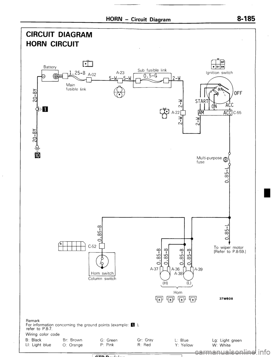
CIRCUIT DIAGRAM
HORN CIRCUIT
fusible link
OFF
Multi-purpose @
fuse
I r t
m
I
2
d
1 To wiper
[Refer to
Horn switch
Column switch mm
mm
I I
I I
2%
$2
dd
I--J!
dd
A-37 A-36
A-39
A-38 motor
P.8-59.1
(H) (U
37W608
Remark
For information concerning the ground points (example:
refer to P.8-7.
Wiring color code
B: Black Br: Brown
G: Green Gr: Gray
L: Blue Lg: Light green
LI: Light blue
0: Orange P: Pink R: Red
Y: Yellow
W: White 1 STB Revision
Page 206 of 284
8486 HORN - Horn
HORN
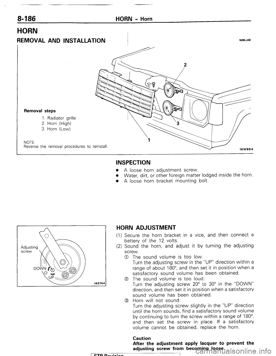
REMOVAL AND INSTALLATION NOBWAE
Removal steps
1. Radiator grille
2. Horn (High)
3. Horn (Low)
NOTE Reverse tne removal procedures to
reinstall.
16W964
169744
INSPECTION o A loose horn adjustment screw.
o Water, dirt, or other foreign matter lodged inside the horn.
l A loose horn bracket mounting bolt.
HORN ADJUSTMENT (1) Secure the horn bracket in a vice, and then connect a
battery of the 12 volts.
(2) Sound the horn, and adjust it by turning the adjusting
screw.
0 The sound volume is too low.
Turn the adjusting screw in the “UP” direction within a
range of about 180”, and then set it in position when a
satisfactory sound volume has been obtained.
0 The sound volume is too loud:
Turn the adjusting screw 20” to 30” in the “DOWN”
direction, and then set it in position when a satisfactory
sound volume has been obtained.
0 Horn will not sound:
Turn the adjusting screw slightly in the “UP” direction
until the horn sounds, find a satisfactory sound volume
by continuing to turn the screw within a range of 180”,
and then set the screw in place. If a satisfactory
volume cannot be obtained, replace the horn.
Caution
After the adjustment apply lacquer to prevent the
adjusting screw from becoming loose.
1 ST6 Revision
Page 208 of 284
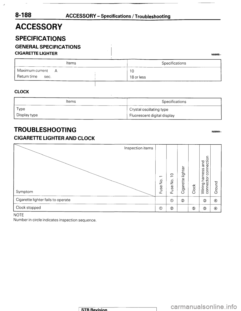
8-188 ACCESSORY - Specifications / Troubleshooting
ACCESSORY
SPECIFICATIONS
GENERAL SPECIFICATIONS
CIGARETTE LIGHTER
I NOBMB-
Items Specifications
Maximum current A
10
Return time
sec. I
I 18 or less
I
CLOCK
Type
Display type Items Specifications
Crystal oscillating type
Fluorescent digital display
TROUBLESHOOTING
ZIGARETTE LIGHTER AND CLOCK
Inspection items
Symptom
Cigarette lighter fails to operate
Clock stopped
NOTE
Number in circle indicates inspection sequence.
MB Revision