MITSUBISHI MONTERO 1987 1.G Owner's Manual
Manufacturer: MITSUBISHI, Model Year: 1987, Model line: MONTERO, Model: MITSUBISHI MONTERO 1987 1.GPages: 284, PDF Size: 14.74 MB
Page 21 of 284
8-1
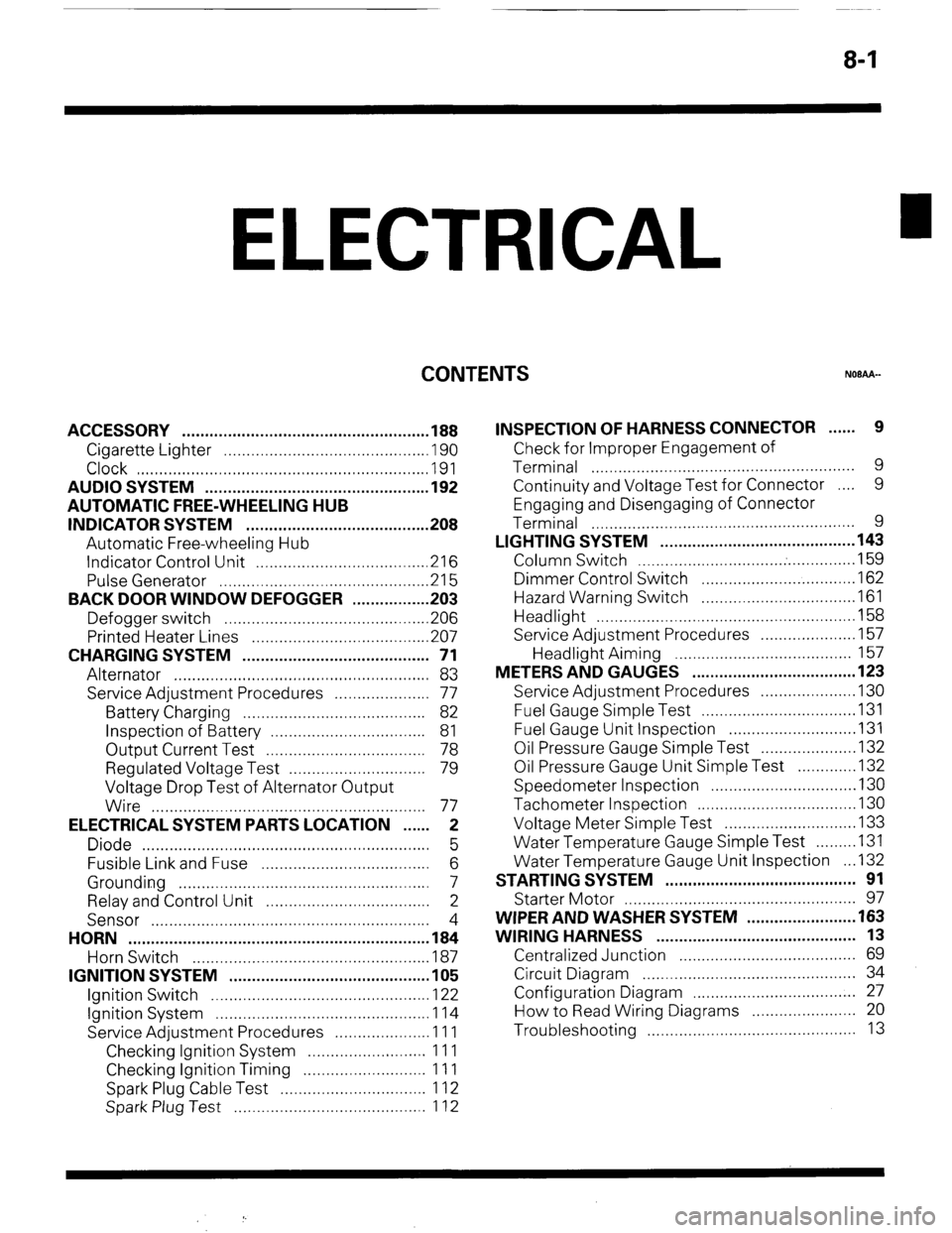
ELECTRICAL
CONTENTS
NOBAA-
ACCESSORY ......................................................
188
Cigarette Lighter ............................................
,190
Clock ...............................................................
,191
AUDIO SYSTEM ................................................
.192
AUTOMATIC FREE-WHEELING HUB
INDICATOR SYSTEM ........................................
208
Automatic Free-wheeling Hub
Indicator Control Unit
..................................... ,216
Pulse Generator ..............................................
215
BACK DOOR WINDOW DEFOGGER
................ .203
Defogger switch ............................................
,206
Printed Heater Lines
...................................... ,207
CHARGING SYSTEM .........................................
71
Alternator ........................................................
83
Service Adjustment Procedures
..................... 77
Battery Charging ........................................
82
Inspection of Battery ..................................
81
Output Current Test ...................................
78
Regulated Voltage Test ..............................
79
Voltage Drop Test of Alternator Output
Wire ............................................................
77
ELECTRICAL SYSTEM PARTS LOCATION
...... 2
Diode ...............................................................
5
Fusible Link and Fuse
..................................... 6
Grounding .......................................................
7
Relay and Control Unit ....................................
2
Sensor .............................................................
4
HORN ..................................................................
184
Horn Switch
.................................................... 187
IGNITION SYSTEM ............................................
105
Ignition Switch
................................................ 122
Ignition System ...............................................
1 14
Service Adjustment Procedures
.................... .l 1 1
Checking Ignition System
..........................
11 1
Checking Ignition Timing
...........................
11 1
Spark Plug Cable Test
................................
1 12
Spark Plug Test
.......................................... 1 12 INSPECTION OF HARNESS CONNECTOR ...... 9
Check for Improper Engagement of
Terminal .......................................................... 9
Continuity and Voltage Test for Connector .... 9
Engaging and Disengaging of Connector
Terminal ..........................................................
9
LIGHTING SYSTEM ........................................... 143
Column Switch
................................ .
.............. .I59
Dimmer Control Switch
................................. .I62
Hazard Warning Switch
................................. .I61
Headlight ........................................................ ,158
Service Adjustment Procedures
.................... .I57
Headlight Aiming .......................................
157
METERS AND GAUGES .................................... 123
Service Adjustment Procedures
.................... .I30
Fuel Gauge Simple Test ................................. .I31
Fuel Gauge Unit Inspection ........................... .I31
Oil Pressure Gauge Simple Test
.................... .I32
Oil Pressure Gauge Unit Simple Test
............ ,132
Speedometer Inspection
............................... .I30
Tachometer Inspection .................................. ,130
Voltage Meter Simple Test
............................ .I33
Water Temperature Gauge Simple Test
....... ..I3 1
Water Temperature Gauge Unit Inspection
. ..I3 2
STARTING SYSTEM .......................................... 91
Starter Motor ............ ....................................... 97
WIPER AND WASHER SYSTEM
....................... .163
WIRING HARNESS ............................................ 13
Centralized Junction ....................................... 69
Circuit Diagram ............................................... 34
Configuration Diagram .................................... 27
How to Read Wiring Diagrams ....................... 20
Troubleshooting .............................................. 13
Page 22 of 284
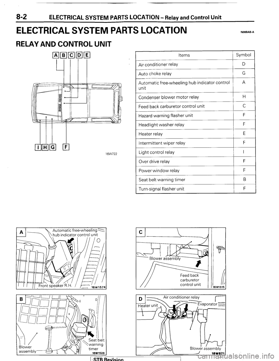
8-2 ELECTRICAL SYSTEM PARTS LOCATION - Relay and Control Unit
ELECTRICAL SYSTEM IPARTS LOCATION NOIBAB-A
RELAY AND CONTROL UNIT
16W722
n 17
hub indicator control unit A A Automatic free-wheeling 2
Blower
assembiy& x v/i 16W152B Items Symbol
--
Air conditioner relay D
--
Auto choke relay G
--
Automatic free-wheeling hub indicator control
A
unit
Condenser blower motor relay H
Feed back carburetor control unit C
Hazard warning flasher unit F
Headlight washer relay F
Heater relay E
Intermittent wiper relay F
~___
Light control relay I
~___
Over drive relay F
Power window relay F
Seat belt warning timer B
Turn-signal flasher unit F
carburetor
control unit
Air conditioner relay
d--- I- Jr Evaporator E
1 .STB Re\iision
Page 23 of 284
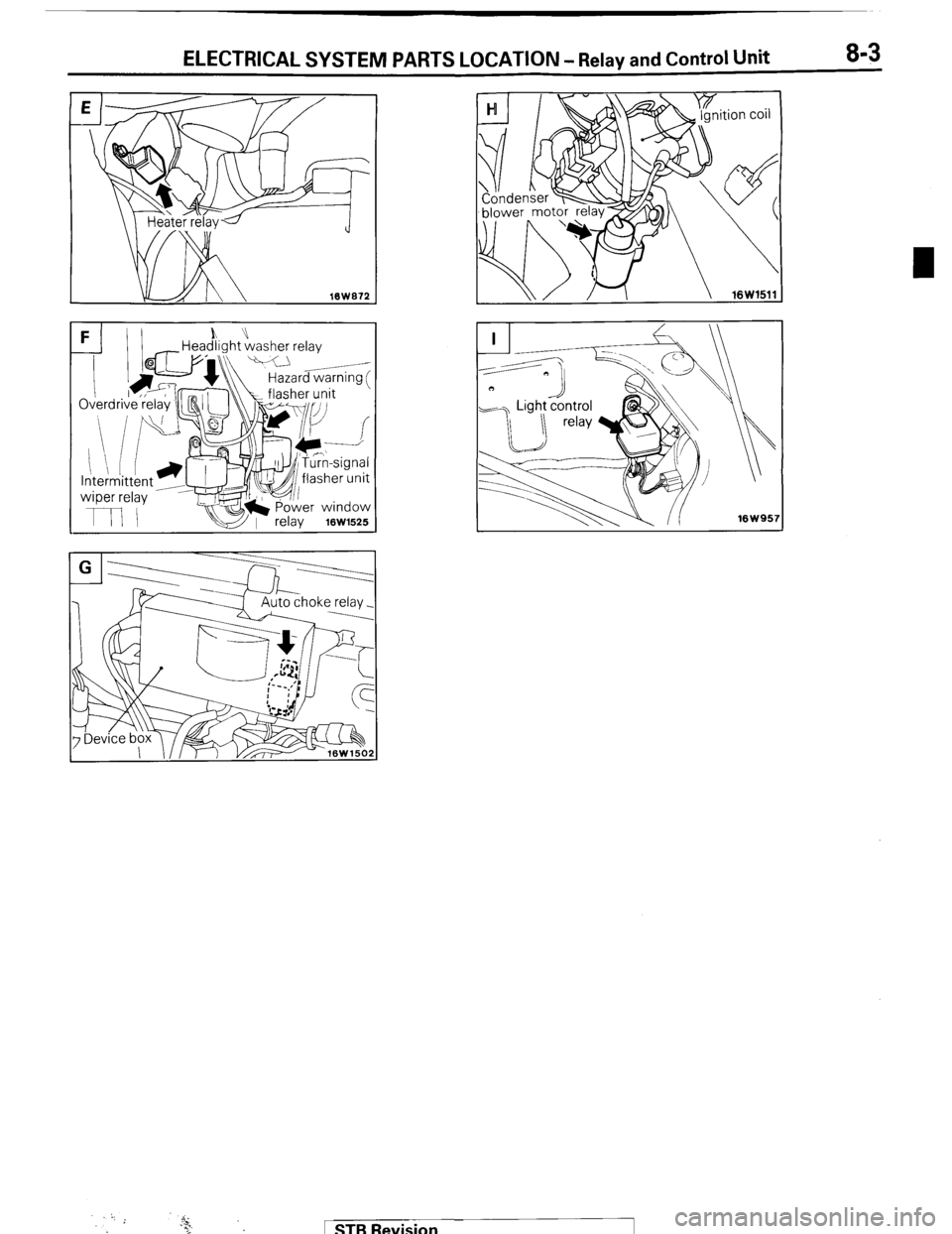
ELECTRICAL SYSTEM PARTS LOCATION - Relay and Control Unit 8-3
FI)I h” -Headlight washer relay
k\\ Hazard warnina f
1 STB Revision
Page 24 of 284
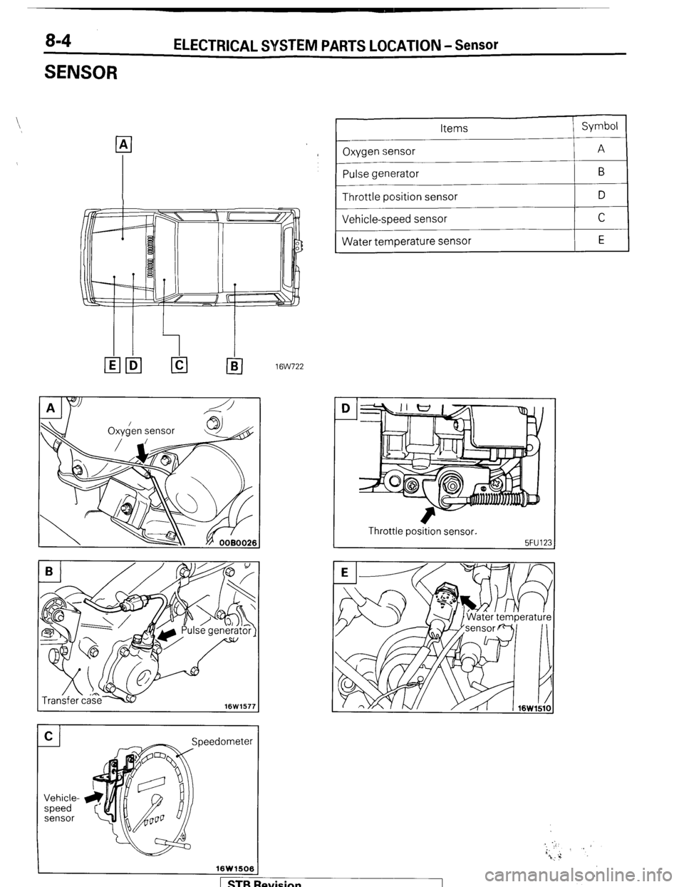
8-4
SENSOR ELECTRICAL SYSTEM PARTS LOCATION - Sensor
I leedometer
16W1506
p
Items
Oxygen sensor
-
Pulse generator --
Throttle position sensor
_____
Vehicle-speed sensor
~~
Water temperature sensor Symbol
A B
D C
E
ltw722
I Throttle position sensor.
I
Revision
Page 25 of 284
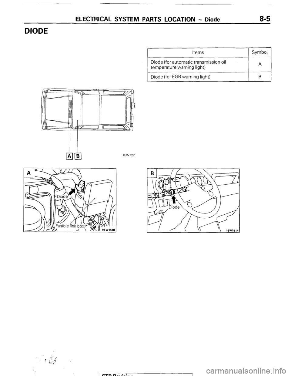
DIODE
ELECTRICAL SYSTEM PARTS LOCATION - Diode 8-5
Diode (for automatic transmission oil
Diode (for EGR warning light)
1 @NJ22
STB Revision
Page 26 of 284
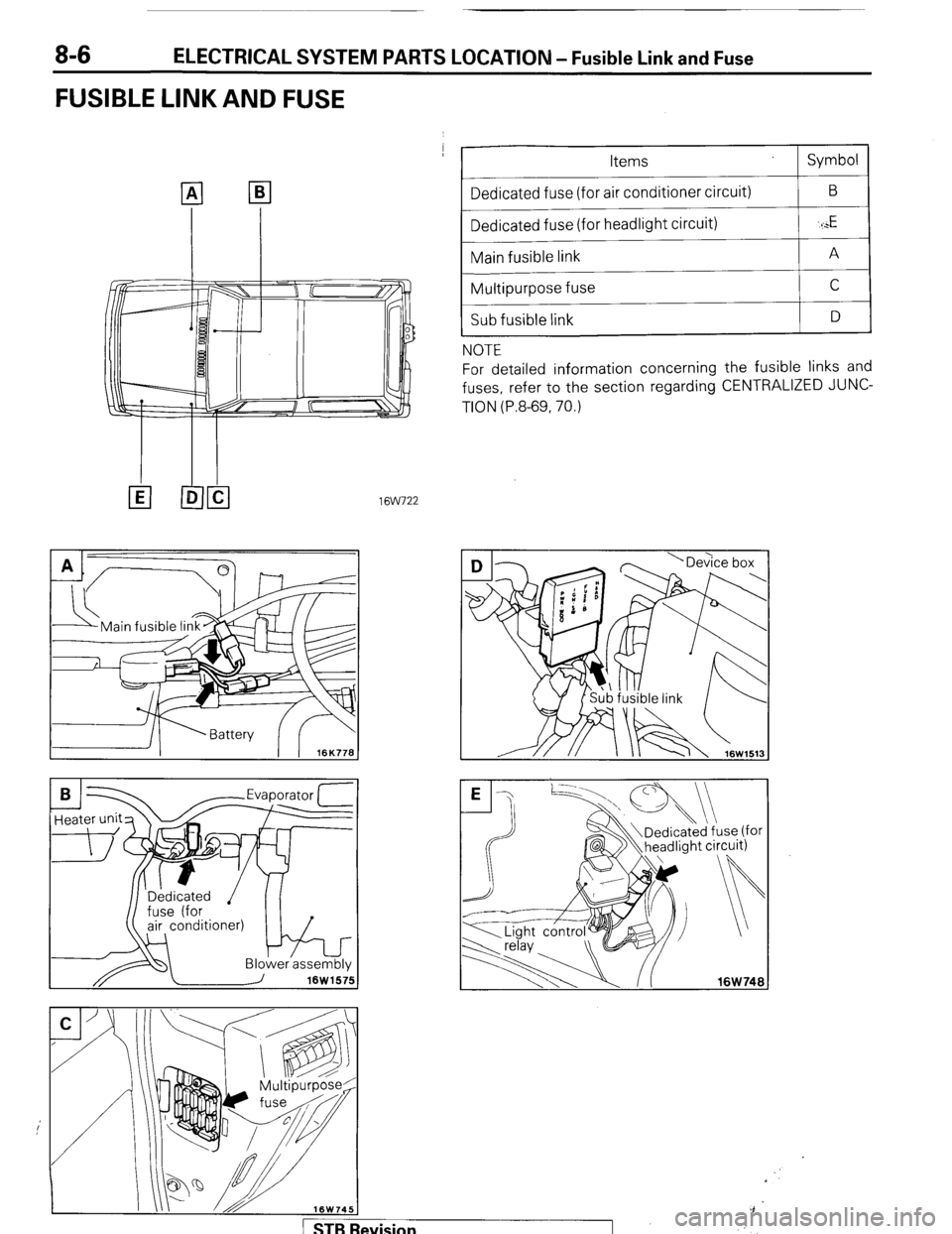
ELECTRICAL SYSTEM PARTS LOCATION - Fusible Link and Fuse
FUSIBLE LINK AND FUSE
--
Items
Dedicated fuse (for air conditioner circuit)
Dedicated fuse (for headlight circuit)
Main fusible link
Multipurpose fuse
Sub fusible link
NOTE Symbol
B
‘I
E
A
C
D
For detailed information concerning the fusible links and
fuses, refer to the section regarding CENTRALIZED JUNC-
TION (P.8-69, 70.)
16W722
-Evaoorator 1
/ STBI levision
Page 27 of 284
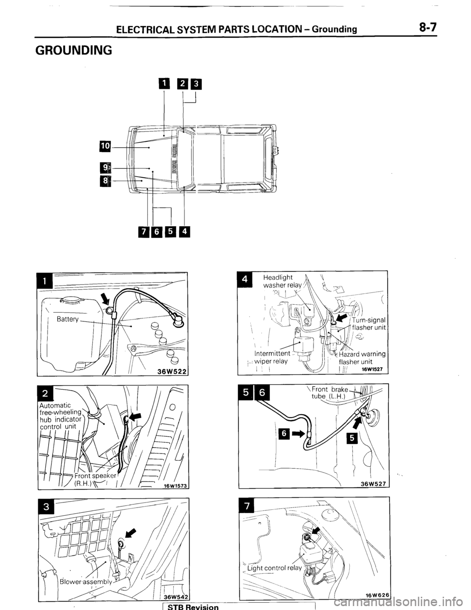
ELECTRICAL SYSTEM PARTS LOCATION -Grounding 8-7
GROUNDING
I
Headlight
washer relay,
h !Ja -/
_ .-----
/ 1 STB Revision
Page 28 of 284
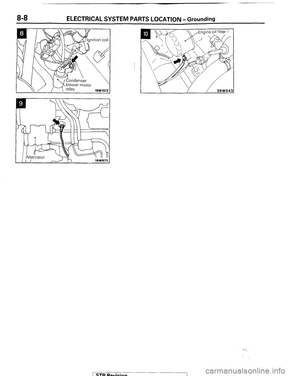
8-8 ELECTRICAL SYSTEM PARTS LOCATION -Grounding
\\/ / 16W1512 1
5. :.,
STB Revision 1 i
Page 29 of 284
INSPECTION OF HARNESS CONNECTOR - Inspection of Harness Connector 8-9
Connect to
harness
16UO500
16R1317
8; 4 16R1319
INSPECTION OF HARNESS
CONNECTOR
NOECAM
CONTINUITY AND VOLTAGE TEST FOR CONNEC-
TOR
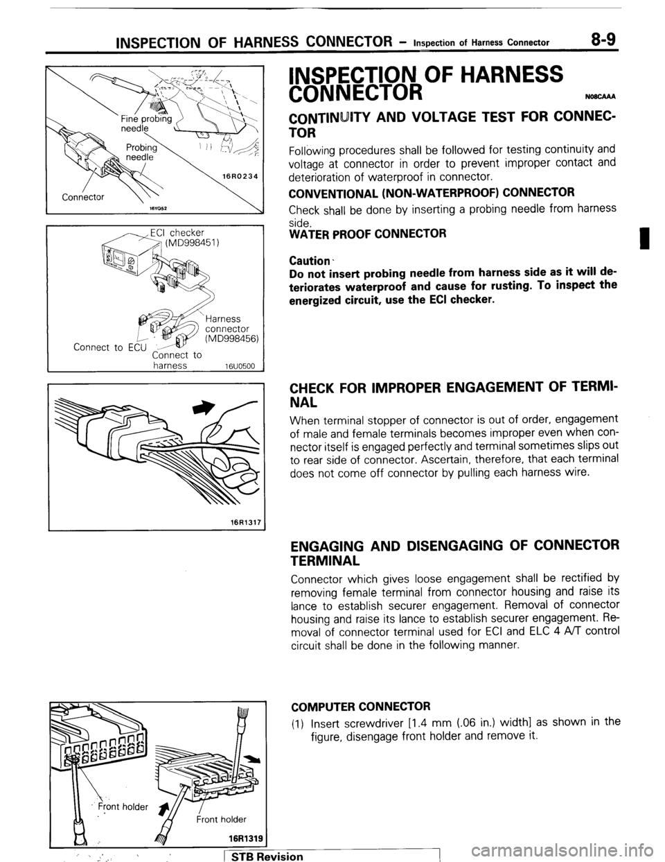
Following procedures shall be followed for testing continuity and
voltage at connector in order to prevent improper contact and
deterioration of waterproof in connector.
CONVENTIONAL (NON-WATERPROOF) CONNECTOR
Check shall be done by inserting a probing needle from harness
side.
WATER PROOF CONNECTOR
Caution.
Do not insert probing needle from harness side as it will de-
teriorates waterproof and cause for rusting. To inspect the
energized circuit, use the ECI checker.
CHECK FOR IMPROPER ENGAGEMENT OF TERMI-
NAL
When terminal stopper of connector is out of order, engagement
of male and female terminals becomes improper even when con-
nector itself is engaged perfectly and terminal sometimes slips out
to rear side of connector. Ascertain, therefore, that each terminal
does not come off connector by pulling each harness wire.
ENGAGING AND DISENGAGING OF CONNECTOR
TERMINAL
Connector which gives loose engagement shall be rectified by
removing female terminal from connector housing and raise its
lance to establish securer engagement. Removal of connector
housing and raise its lance to establish securer engagement. Re-
moval of connector terminal used for ECI and ELC 4 ,4/l control
circuit shall be done in the following manner.
COMPUTER CONNECTOR
(1) Insert screwdriver [1.4 mm (06 in.) width] as shown in the
figure, disengage front holder and remove it.
:
j ’ . _. 1 STB Revision
Page 30 of 284
8-10 INSPECTION OF HARNESS CONNECTOR - Inspection of Harness Connector
Housing lance
-5
1 16R1321
’ Needle
16Ffi322
Housing lance
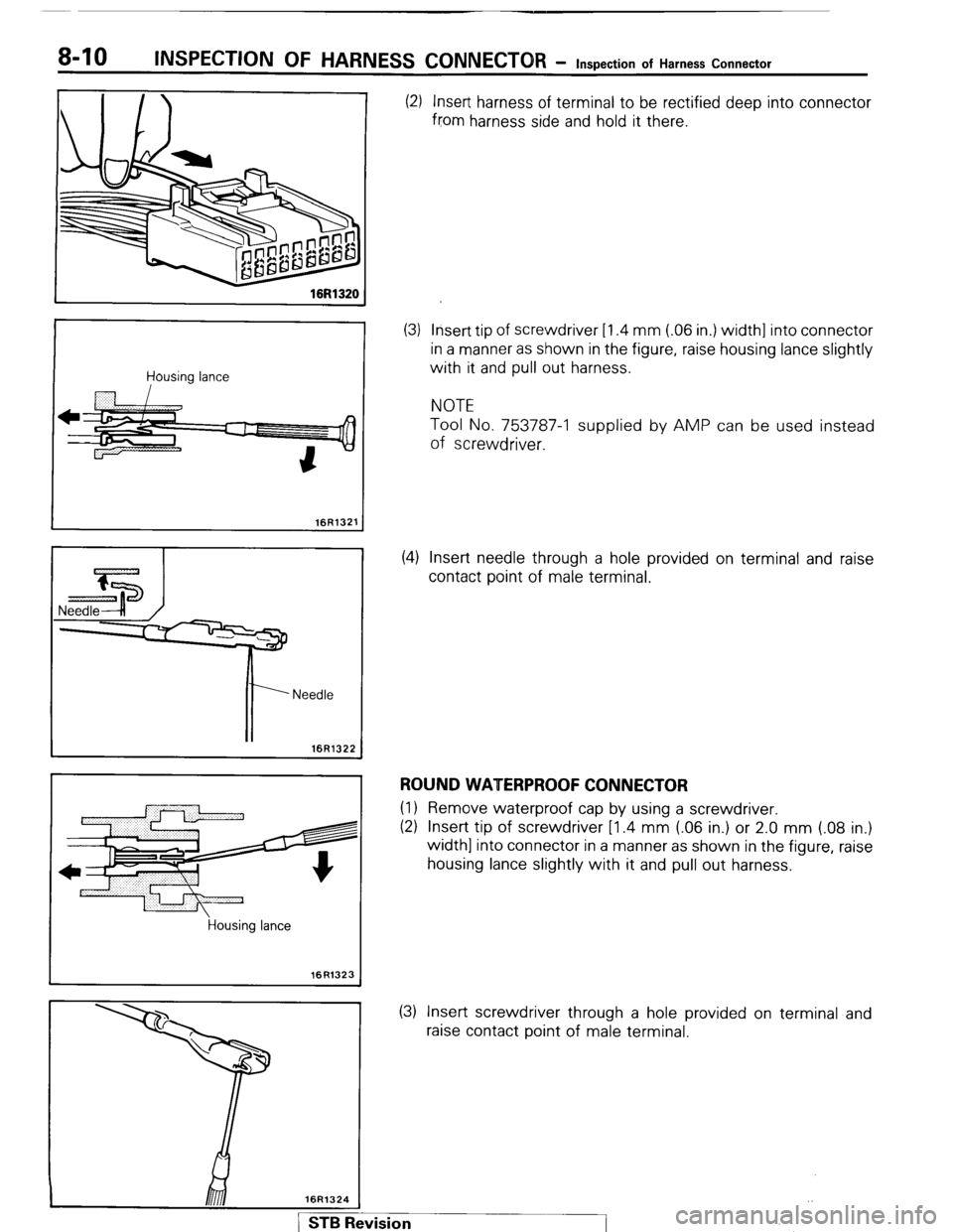
16R1323 (2) Insert harness of terminal to be rectified deep into connector
from harness side and hold it there.
(3) Insert tip of screwdriver [1.4 mm (.06 in.) width] into connector
in a manner as shown in the figure, raise housing lance slightly
with it and pull out harness.
NOTE
Tool No. 753787-l supplied by AMP can be used instead
of screwdriver.
(4) Insert needle through a hole provided on terminal and raise
contact point of male terminal.
ROUND WATERPROOF CONNECTOR (1) Remove waterproof cap by using a screwdriver.
(2) Insert tip of screwdriver [1.4 mm (.06 in.) or 2.0 mm (.08 in.)
width] into connector in a manner as shown in the figure, raise
housing lance slightly with it and pull out harness.
(3) Insert screwdriver through a hole provided on terminal and
raise contact point of male terminal.