MITSUBISHI MONTERO 1987 1.G Repair Manual
MONTERO 1987 1.G
MITSUBISHI
MITSUBISHI
https://www.carmanualsonline.info/img/19/7559/w960_7559-0.png
MITSUBISHI MONTERO 1987 1.G Repair Manual
Trending: height, seat adjustment, rims, mileage, audio, fuse box, piston head
Page 51 of 284
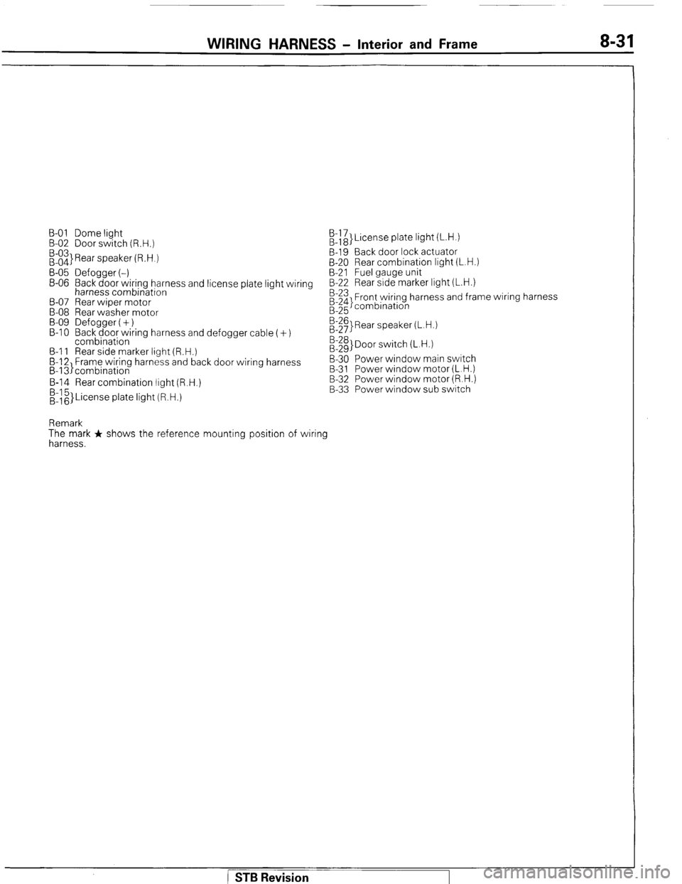
WIRING HARNESS - Interior and Frame 8-31
B-01 Dome light
B-02 Door switch (R.H.)
:::3 Rear speaker (R.H.) /&}License plate light (L.H.)
B-19 Back door lock actuator
B-20 Rear combination light (L.H.)
B-05 Defogger (-) B-21 Fuel gauge unit
B-06 Back door wiring harness and license plate light wiring B-22 Rear side marker light (L.H.)
harness combination
B-07 Rear wiper motor
B-08 Rear washer motor
B-09 Defogger (+)
B-l 0 Back door wiring harness and defogger cable (+)
combination
B-l 1 Rear side marker light (R.H.)
B-12 Frame wiring harness and back door wiring harness
B-13)combination B-23 Front wiring harness and frame wiring harness
;:g combination
E$ Rear speaker (L.H.)
:::g> Door switch (L.H.)
B-30 Power window main switch
B-31 Power window motor (L.H.)
B-14 Rear combination light (R.H.)
&z}License plate light (R.H.) B-32 Power window motor (R.H.)
B-33 Power window sub switch
Remark
The mark + shows the reference mounting position of wiring
harness.
STB Revision
Page 52 of 284
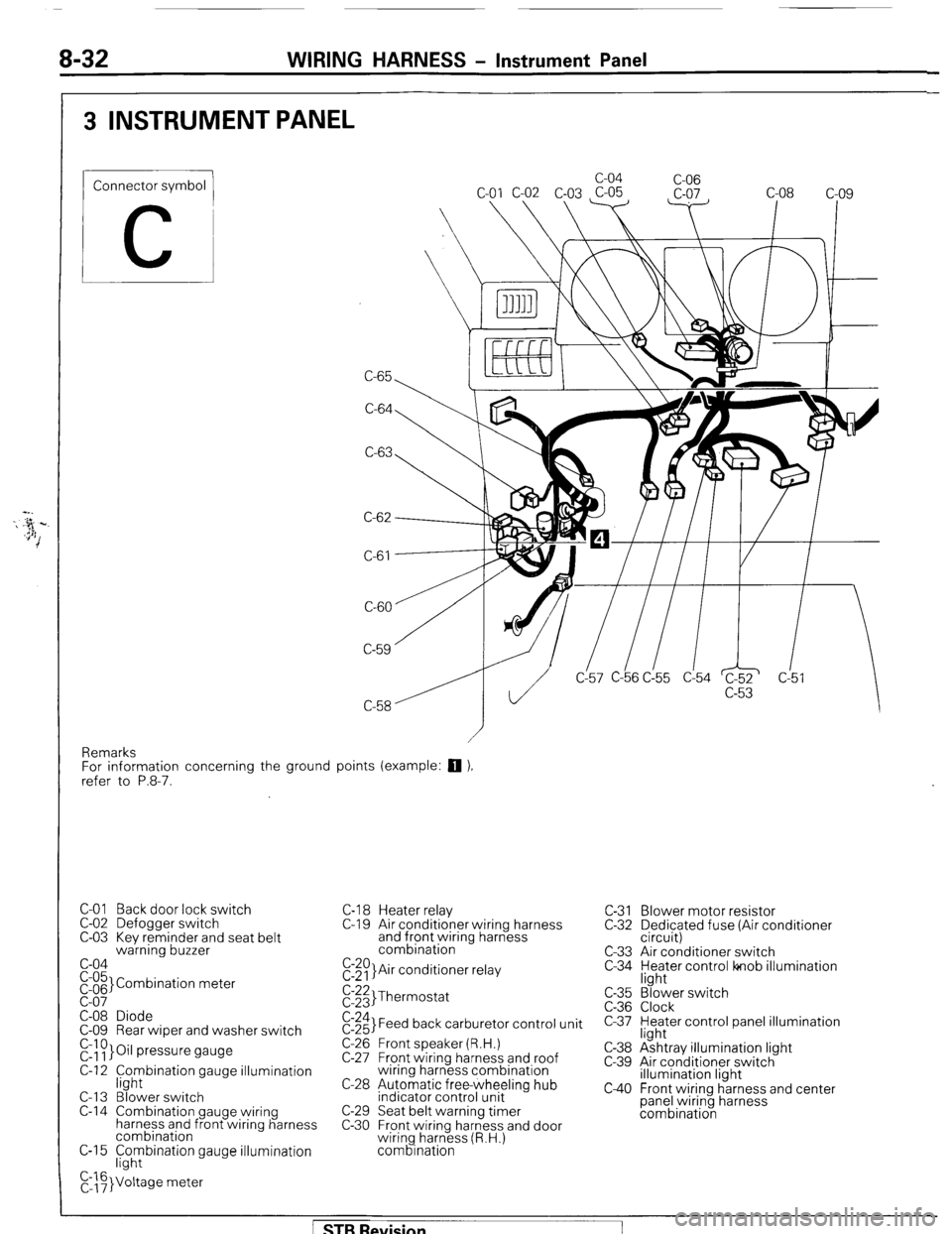
8-32 WIRING HARNESS - Instrument Panel
3 INSTRUMENT PANEL
Connector symbol
C
C-65 c-04
C-06
C-64
C-63
C-61
CL57 C-b6 C!55 d54 c!5
Remarks
For information concerning the ground points (example:
q ),
refer to P.8-7.
C-01 Back door lock switch
C-02 Defogger switch
C-03 Kev reminder and seat belt
warning buzzer
c-04
pi;’ Combination meter
C-08 Diode
C-09 Rear wiper and washer switch
r&~}Oil pressure gauge
C-12 f;hybination gauge illumination
C-l 3 Blower switch
C-14 Combination gauge wiring
harness and front wiring harness
combination
C-15 F;hybination gauge illumination
C,::F}Voltage meter C-l 8 Heater relay
C-l 9 Air conditioner wiring harness
and front wiring harness
combination
E:$)}Air conditioner relay C-31 Blower motor resistor
C-32 Dedicated fuse (Air conditioner
circuit)
C-33 Air conditioner switch
C-34 yl;Jer control lonob illumination
$:;;I Thermostat
$:;;I Feed back carburetor control unit
C-26 Front speaker (R.H.)
C-27 Front wiring harness and roof
wiring harness combination
C-28 Automatic free-wheeling hub
indicator control unit
C-29 Seat belt warning timer
C-30 Front wiring harness and door
wiring harness (R.H.)
combination c-35
C-36
c-37
C-38
c-39
c40
“3’ ‘. Blower switch
Clock
Heater control panel illumination
light
Ashtray illumination light
Air conditioner switch
illumination light
Front wiring harness and center
panel wiring harness
combination
[ STB Revision
Page 53 of 284
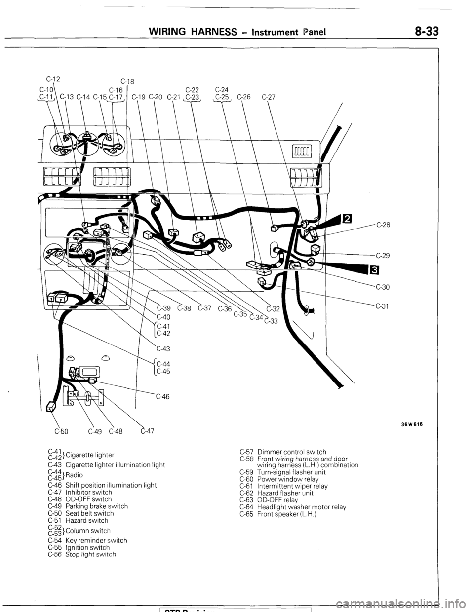
WIRING HARNESS - Instrument Panel 8-33
cy50 C149 Cl48 c-47
El$,}Cigarette lightet
C-43 Cigarette lighter illumination light
E::$ Radio
C-46 Shift position illumination light
C-47 Inhibitor switch
C-48 OD-OFF switch
C-49 Parking brake switch
C-50 Seat belt switch
C-51 Hazard switch
E3 Column switch
C-54 Key reminder switch
C-55 Ignition switch
C-56 Stop light switch C-57 Dimmer control switch
C-58 Front wiring harness and door
wiring harness (L.H.) combination
C-59 Turn-signal flasher unit
C-60 Power window relay
C-61 Intermittent wiper relay
C-62 Hazard flasher unit
C-63 OD-OFF relay
C-64 Headlight washer motor relay
C-65 Front speaker (L.H.)
Ision
Page 54 of 284
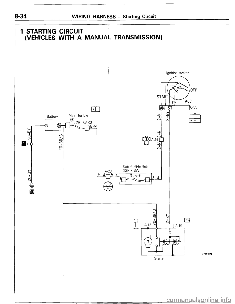
8-34 WIRING MARNESS - Starting Circuit
1 STARTING CIRCUIT
(VEHICLES WITH A MANUAL TRANSMISSION)
Ignition switch
Battery Main fusible
link
@.25B+
A-23 Sub fusible link
(IGN - SW)
7
BIT/B
M
2
M
I
A-15 F=
TA RT
L
1!
z
cl
m w BY
A
Starter
37W620
1 STB Revision
Page 55 of 284
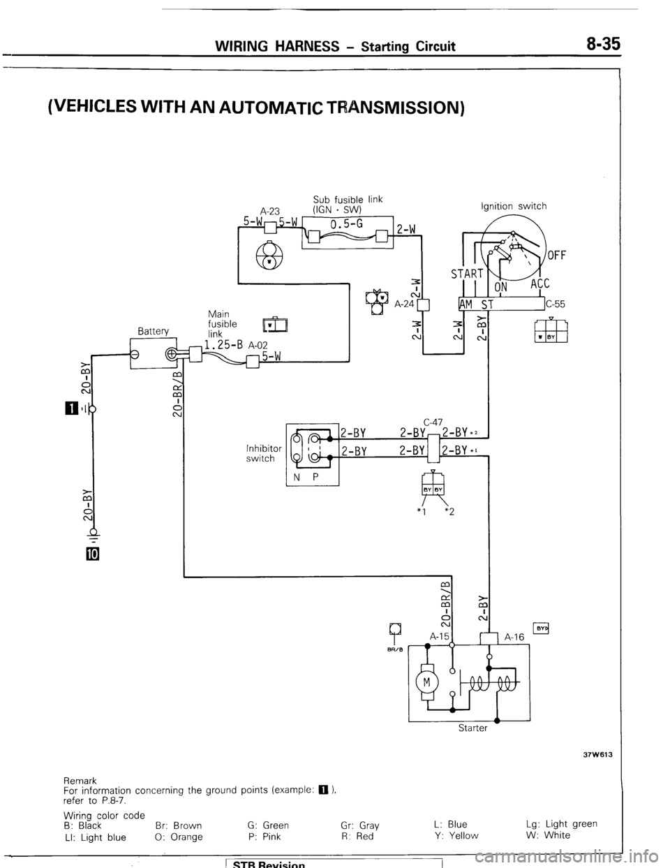
WIRING HARNESS - Starting Circuit 8-35
(VEHICLES WITH AN AUTOMATIC TRANSMISSION)
Battery
-p Main
fusible
lrril ‘I
link
1.25-B A-02
-5-w
A-23 Sub fusible link
(IGN . SW) Ignition switch
U
Inhibitor
switch c-47
a 1 2-BY 2-BY,2-BY*2
I 1
a- 2-BY 2-BY 2-BY*l
1
N P
fTl BY BY
37W613
Remark
For information concerning the ground points (example: 0 ).
refer to P.8-7.
Wiring color code
8: Black Br: Brown G: Green Gr: Gray L: Blue Lg: Light green
LI: Light blue 0: Orange P: Pink R: Red Y: Yellow W: White ) STB Revision
Page 56 of 284
8-36 WIRING HARNESS - Ignition Circuit
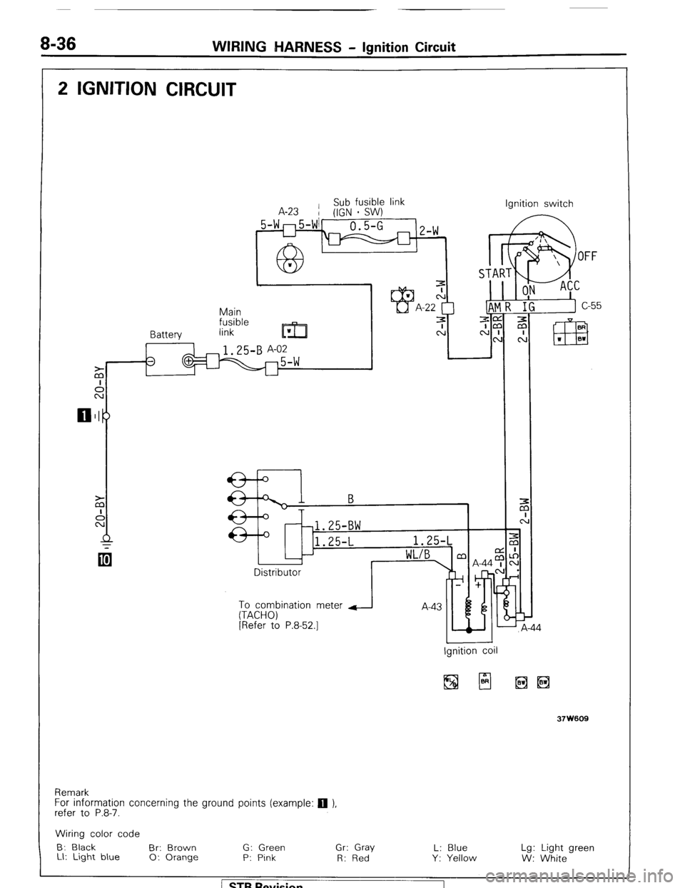
2 IGNITION CIRCUIT
Sub fusible link
A-23
/ (IGN * SW)
Batterv Main
fusible
link
m w Ignition switch
IR
I i
r
Distributor
To combination meter
(TACHO)
[Refer to P.8-52.1
J A-44
37W609
Remark
For information concerning the ground points (example: q ),
refer to P.8-7.
Wiring color code
B: Black
Br: Brown G: Green Gr: Gray L: Blue
Ll: Light blue Lg: Light green
0: Orange P: Pink
R: Red Y: Yellow
W: White
/ STB Revision
7 ‘:
Page 57 of 284
WIRING HARNESS - Charging Circuit 8-37
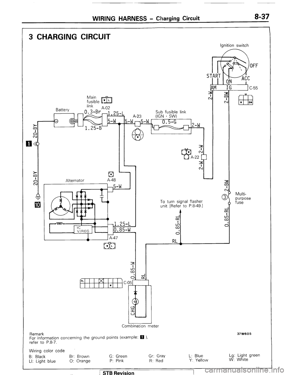
3 CHARGING CIRCUIT
S‘
Main
fusible ’ L m
link
Battery A-02
, 3
Alternator
El A-48 A-23 Sub fusible link
(IGN - SW)
I
3
cl
Ignition switch
.n
1 Comornatron meter
Remark
For information concerning the ground points (example:
q ),
refer to P.8-7.
3
c:
-22
t 3
c!J I
To turn signal flasher
unit [Refer to P.8-49.1
J 3
a
I
6
m ‘I 81
Multi-
purpose
fuse
37W605
Wiring color code
B: Black Br: Brown G: Green Gr: Gray L: Blue Lg: Light green
LI: Light blue 0: Orange P: Pink R: Red Y: Yellow W: White . / STB Revision
Page 58 of 284
8-38 WIRING HARNESS - Feed Back Carburetor Circuit
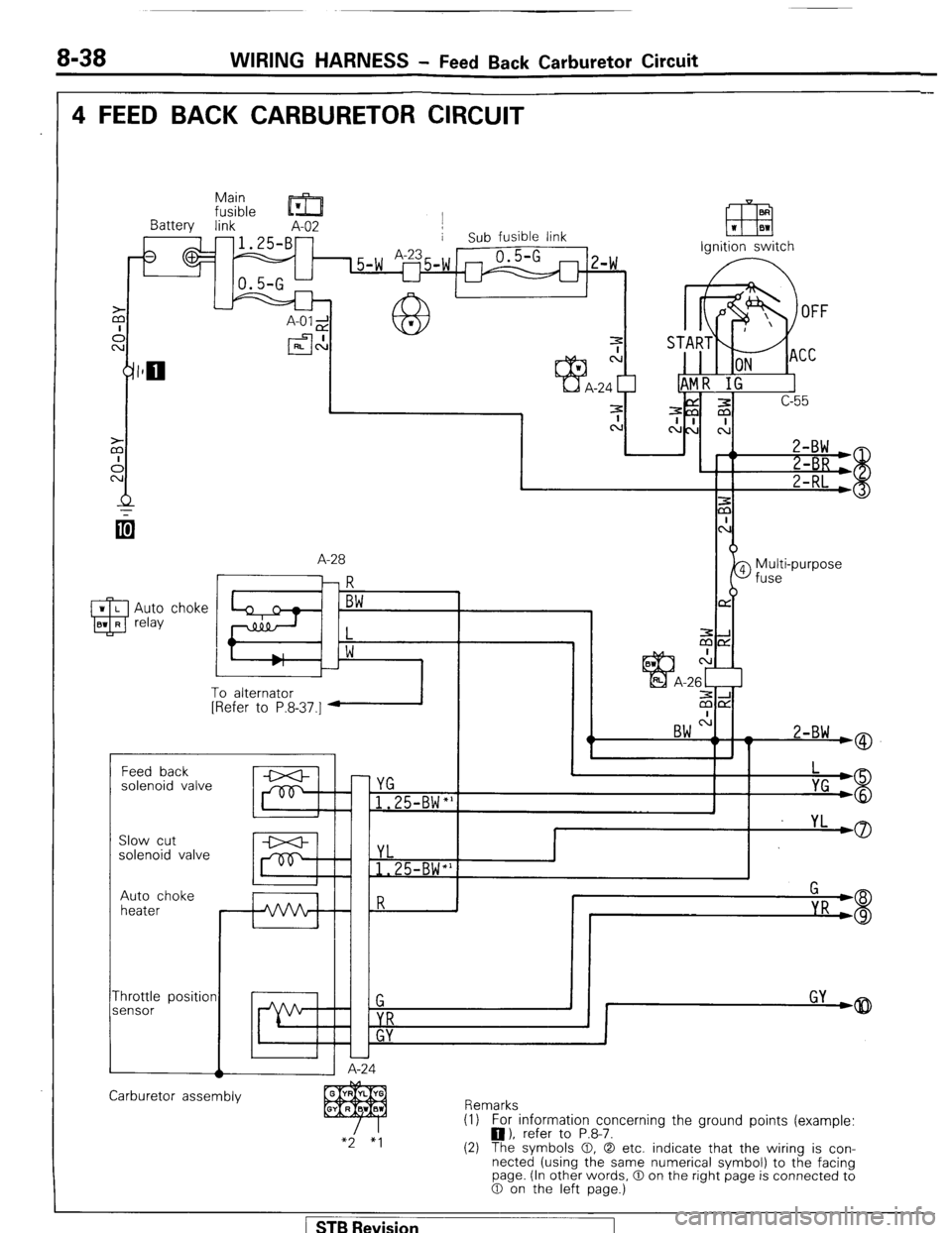
4 FEED BACK CARBURETOR CIRCUIT
Main
fusible ’ m
Battery link A-02 j
-1.25-B- i Sub fusible link
I L uA-2i
I:
a h
W r
efl
EEI W BW
Ignition switch
A-28
qi
--I
zix
c:
-26c-1
ziE2
BW ".
I w 2-BW wQ
To alternator
[Refer to P.8.37.1 1 I
r Feed back
solenoid valve
c YG
1.25-BW"'
I
I yL
,0
P Slow cut
solenoid valve YL
1.25-BW*'
Auto choke
heater
-hrottle position
iensor
A-24 1
Carburetor assembly
Remarks
(1) For information concerning the ground points (example:
0). refer to P.8-7.
(2) The symbols 0, 0 etc. indicate that the wiring is con-
nected (using the same numerical symbol) to the facing
page. (In other words, 0 on the right page is connected to
0 on the left page.)
STB Revision
Page 59 of 284
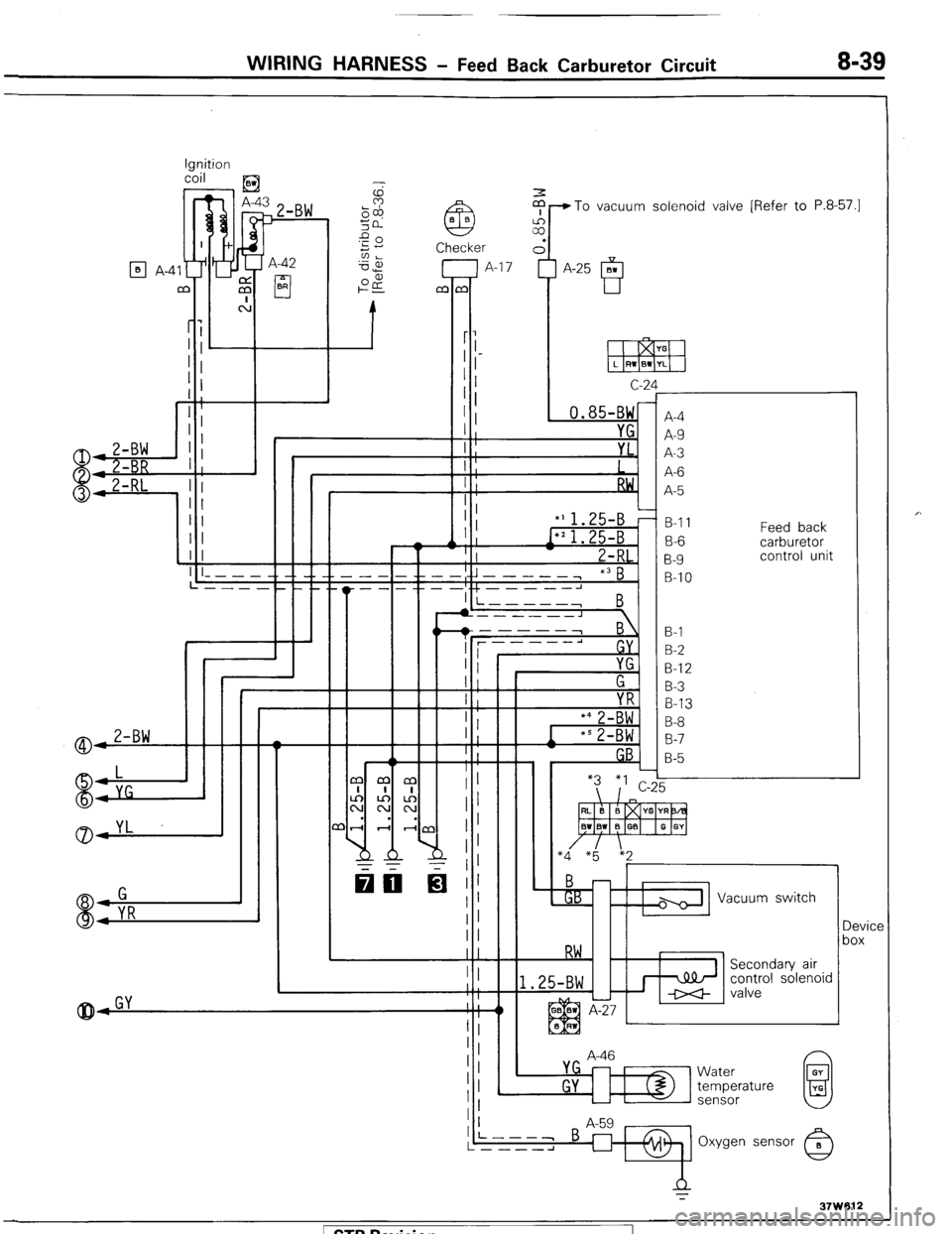
WIRING HARNESS - Feed Back Carburetor Circuit 8-39
Ignition
coil
) _ ,E3
$-To vacuum solenoid valve [Refer to P.8-57.1
7 A-42
cl BR
q A-4
c-2
, 0.85-BW
I YG
I ;
I : YL.
I
I ;
RW,
I :
‘A
f
r
A-4
A-9
A-3
A-6
A-5
B-l 1
B-6
B-9
B-IO Feed back
carburetor
control unit
I
II
II
(I I
1 I ! ! I I- - - - -. -_ __ __
L---- __._._
I +L----J I i-----,
B
B-l
B-2
B-l 2
B-3
B-13
B-8
B-7
B-5
A-46 Vacuum switch
Device
box
control solenoid
L
L
Water
temperature
sensor 1 STB Revision
Page 60 of 284
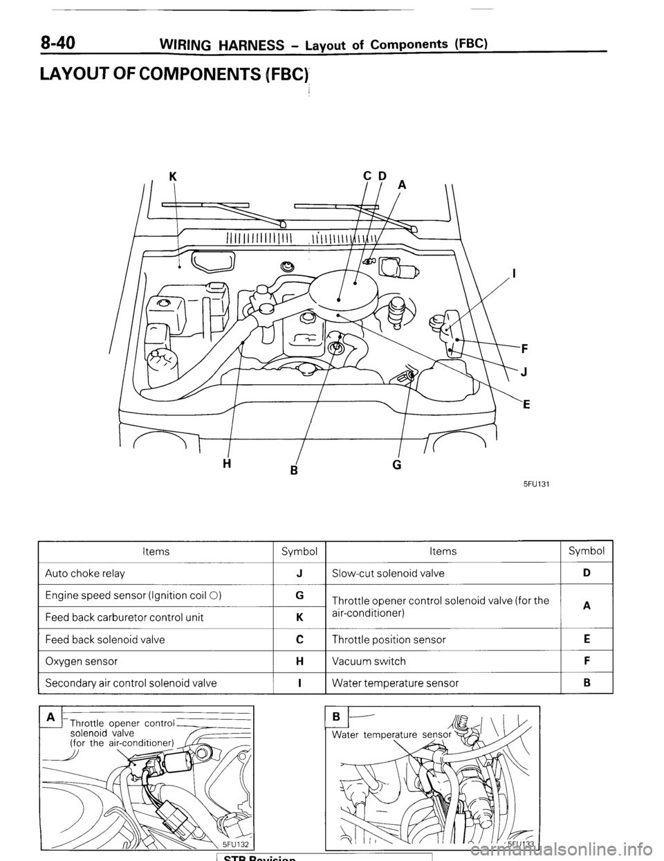
8-40 WIRING HARNESS - Layout of Components WC)
LAYOUT OFCOMPONENJS [FBC)
CD
II A
5FU131
Items
Symbol Items Symbol
Auto choke relay J Slow-cut solenoid valve D
Engine speed sensor (Ignition coil 0)
Feed back carburetor control unit G
Throttle opener control solenoid valve (for the
A
K air-conditioner)
Feed back solenoid valve
I
C Throttle position sensor
I E
Oxygen sensor
I H Vacuum switch
I F
Secondary air control solenoid valve
I I 1 Water temperature sensor
I B
Throttle opener contr
solenoid valve
Trending: 8-119, 8-118, reservoir, fuse box, distributor, AUX, coolant temperature
