MITSUBISHI MONTERO 1987 1.G Owner's Guide
Manufacturer: MITSUBISHI, Model Year: 1987, Model line: MONTERO, Model: MITSUBISHI MONTERO 1987 1.GPages: 284, PDF Size: 14.74 MB
Page 31 of 284

INSPECTION OF HARNESS CONNECTOR - Inspection of Harness Connector 8-71
RECTANGULAR WATERPROOF CONNECTOR
(1) Disengage front holder by using a screwdriver and remove it.
(2) Insert tip of screwdriver [*0.8 mm (03 in.) width] into connec-
tor in a manner as shown in the figure, push it lightly to raise
housing lancer and pull out harness.
*If right size screwdriver is not available, convert a conven-
tional driver to suit the size.
Housing lance
16R13 26
16R1329
L 16R1326)
(2)
Terminal lance
16Rl330
1 STB Revision (3) Press contact point of male terminal down by holding a screw-
driver [1.4 mm (.06 in.) width] in a manner as shown in the
figure.
INJECTOR CONNECTOR
(1) Remove waterproof cap.
Insert tip of screwdriver [1.4
in a manner as shown in the
pull out harness. mm (06 in.) width] into connector
figure, press in terminal lance and
Page 32 of 284
![MITSUBISHI MONTERO 1987 1.G Owners Guide 8-12 INSPECTION OF HARNESS CONNECTOR - Inspection of Harness Connector
16R132i
(3) Press contact point of male terminal down by holding a screw-
driver Il.4 mm (.06 in.) width] in a manner as shown MITSUBISHI MONTERO 1987 1.G Owners Guide 8-12 INSPECTION OF HARNESS CONNECTOR - Inspection of Harness Connector
16R132i
(3) Press contact point of male terminal down by holding a screw-
driver Il.4 mm (.06 in.) width] in a manner as shown](/img/19/7559/w960_7559-31.png)
8-12 INSPECTION OF HARNESS CONNECTOR - Inspection of Harness Connector
16R132i
(3) Press contact point of male terminal down by holding a screw-
driver Il.4 mm (.06 in.) width] in a manner as shown in the
figure.
Caution
Correct lancer to be in proper condition before terminal is
inserted into connector.
I
1 STB Revision
Page 33 of 284
WIRING HARNESS - Troubleshooting 8-13
WIRING HARNESS
TROUBLESHOOTING NO8DAAA
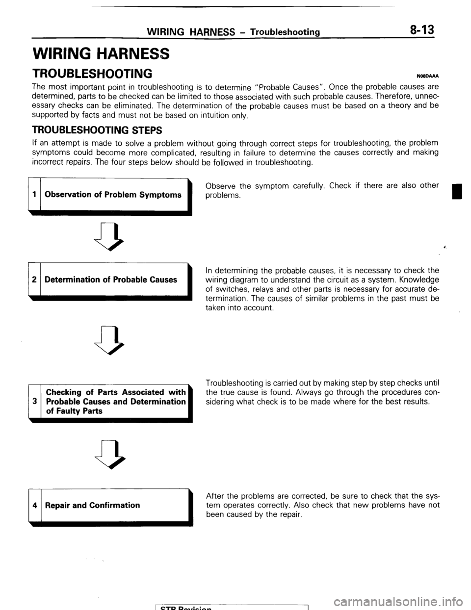
The most important point in troubleshooting is to determine “Probable Causes”. Once the probable causes are
determined, parts to be checked can be limited to those associated with such probable causes. Therefore, unnec-
essary checks can be eliminated. The determination of the probable causes must be based on a theory and be
supported by facts and must not be based on intuition only.
TROUBLESHOOTING STEPS
If an attempt is made to solve a problem without going through correct steps for troubleshooting, the problem
symptoms could become more complicated, resulting in failure to determine the causes correctly and making
incorrect repairs. The four steps below should be followed in troubleshooting.
1 1 Observe the
1 problems. symptom carefully. Check if there are also other
1 Observation of Problem Symptoms
b
0,
2 Determination of Probable Causes
In determining the probable causes, it is necessary to check the
wiring diagram to understand the circuit as a system. Knowledge
of switches, relays and other parts is necessary for accurate de-
termination. The causes of similar problems in the past must be
taken into account.
Checking of Parts Associated with Troubleshooting is carried out by making step by step checks until
the true cause is found. Always go through the procedures con-
sidering what check is to be made where for the best results.
14 1 Repair and Confirmation
After the problems are corrected, be sure to check that the sys-
1 been caused by the repair, tem operates correctly Also check that new problems have not
1 STB Revision
1
Page 34 of 284
8-14 WIRING HARNESS - Troubleshooting
1680222
Changeover knob 1680224
1680225 1
1680226
INSPECTION
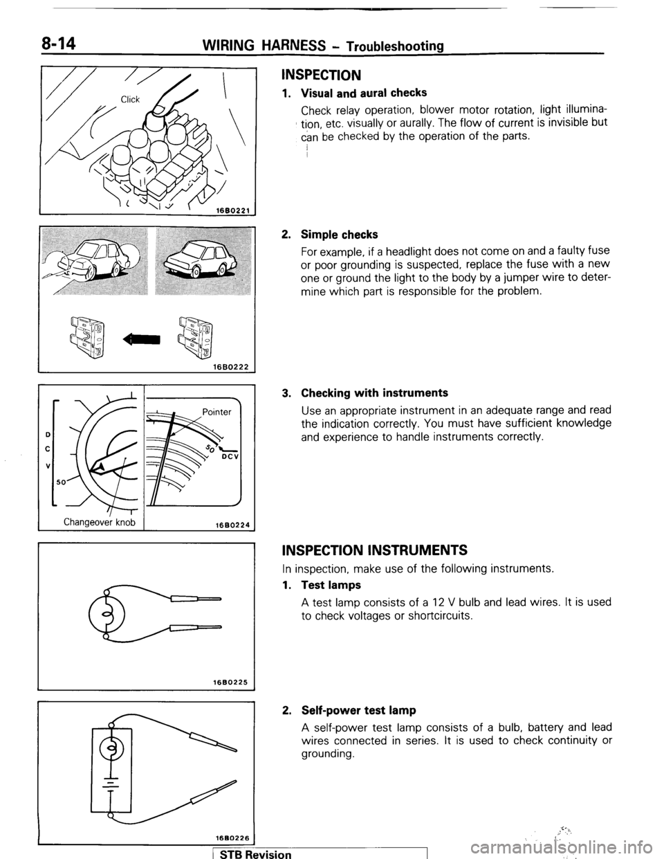
1. Visual and aural checks
Check relay operation, blower motor rotation, light illumina-
tion, etc. visually or aurally. The flow of current is invisible but
can be checked by the operation of the parts.
I
2. Simple checks
For example, if a headlight does not come on and a faulty fuse
or poor grounding is suspected, replace the fuse with a new
one or ground the light to the body by a jumper wire to deter-
mine which part is responsible for the problem.
3. Checking with instruments
Use an appropriate instrument in an adequate range and read
the indication correctly. You must have sufficient knowledge
and experience to handle instruments correctly.
INSPECTION INSTRUMENTS
In inspection, make use of the following instruments.
1. Test lamps
A test lamp consists of a 12 V bulb and lead wires. It is used
to check voltages or shortcircuits.
2. Self-power test lamp
A self-power test lamp consists of a bulb, battery and lead
wires connected in series. It is used to check continuity or
grounding.
,.!‘?i,
,, 6
,‘.’
1 STB Revision
Page 35 of 284
WIRING HARNESS - Troubleshooting 8-15
1660227
Black lead wire
Ground y
1680228
Normal open (NO) type
OFF
ax
Current does not flow ON
Current flows
Normal close (NC) type
OFF
l-2
Current flows ON
-op--
IX
Current does not flow
1680229
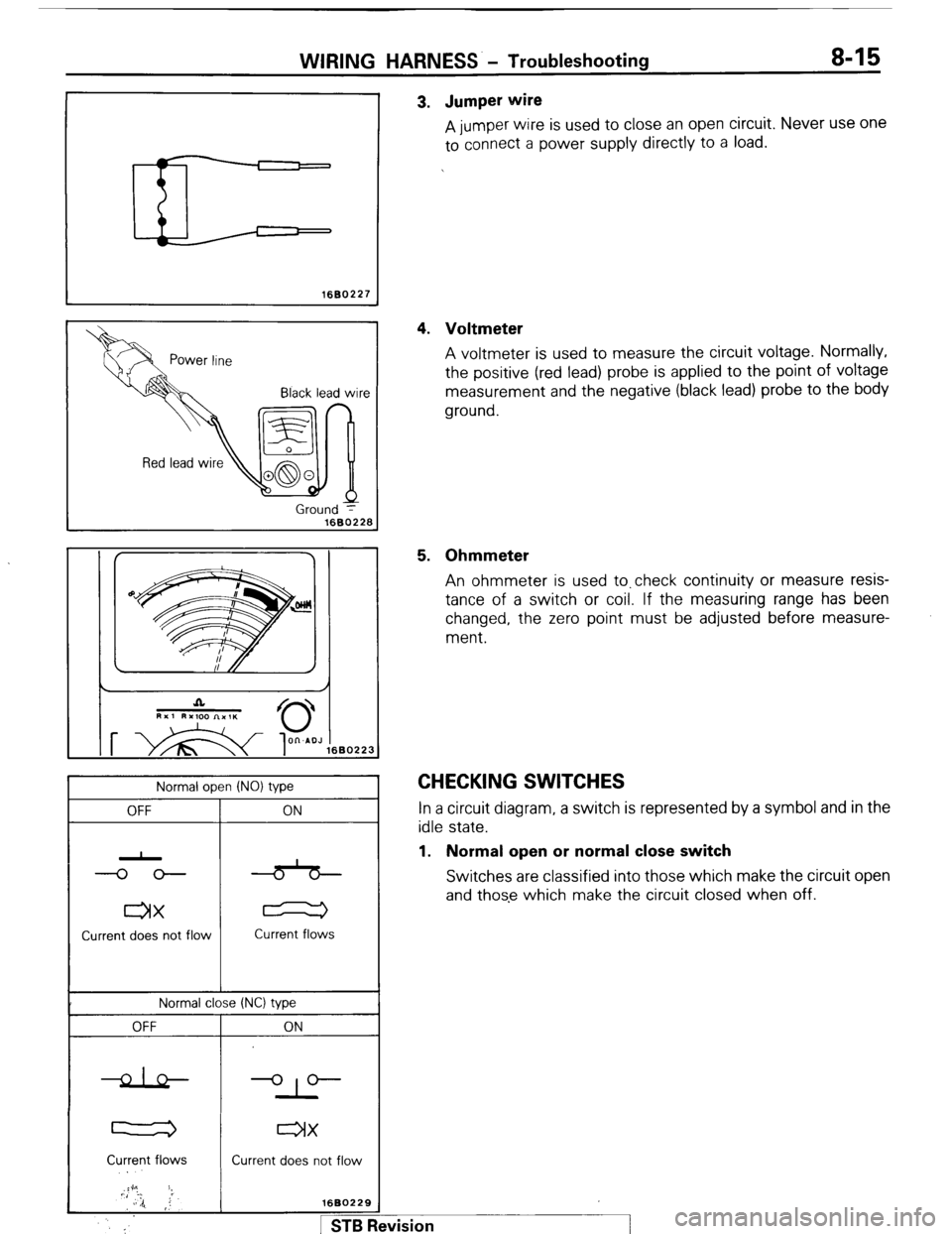
pm I 3. Jumper wire
A jumper wire is used to close an open circuit. Never use one
to connect a power supply directly to a load.
4. Voltmeter
A voltmeter is used to measure the circuit voltage. Normally,
the positive (red lead) probe is applied to the point of voltage
measurement and the negative (black lead) probe to the body
ground.
5. Ohmmeter
An ohmmeter is used to.check continuity or measure resis-
tance of a switch or coil. If the measuring range has been
changed, the zero point must be adjusted before measure-
ment.
CHECKING SWITCHES In a circuit diagram, a switch is represented by a symbol and in the
idle state.
1. Normal open or normal close switch
Switches are classified into those which make the circuit open
and those which make the circuit closed when off.
#vision
I
Page 36 of 284
8-16 WIRING HARNESS - Troubleshooting
OFF
1st stage
2nd stage
3rd stage
1
--_
4th stage
1660230
16W896
Cover
Coil
Iron
piece Spring
Iron
core
Contact
1660231
I
l-
Battery:
I
-
d
T Relav
T I
I 1660232 1
Normal ooen (NO) tvoe
Deenergized state Energized state
I
1
2
ED
3
4
1 2
BP
3
4
1 YZZZw;6B0233 CurreZ! not flow
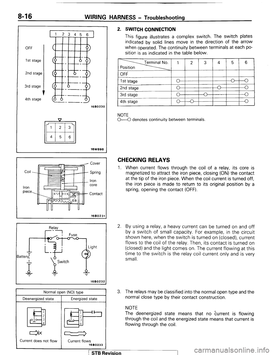
2. SWITCH CONNECTION
This figure illustrates a complex switch. The switch plates
indicated by solid lines move in the direction of the arrow
when
operated. The continuity between terminals at each po-
sition is as indicated in the table below.
NOTE
M denotes continuity between terminals.
CHECKING RELAYS
1. When current flows through the coil of a relay, its core is
magnetized to attract the iron piece, closing (ON) the contact
at the tip of the iron piece. When the coil current is turned off,
the iron piece is made to return to its original position by a
spring, opening the contact (OFF).
2. By using a relay, a heavy current can be turned on and off
by a switch of small capacity. For example, in the circuit
shown here, when the switch is turned on (closed), current
flows to the coil of the relay. Then, its contact is turned on
(closed) and the light comes on. The current flowing at this
time to the switch is the relay coil current only and is very
small.
3. The relays may be classified into the normal open type and the
normal close type by their contact construction.
NOTE
The deenergized state means that no kurrent is flowing
through the coil and the energized state means that current is
flowing through the coil.
J . . . I 1 STB Revmon
Page 37 of 284
Normal close INC) type
Deenergized state
Energized state
I
WIRING HARNESS - Troubleshooting 8-17
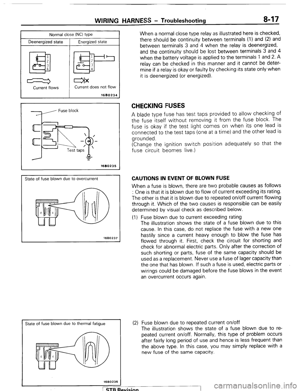
When a normal close type relay as illustrated here is checked,
there should be continuity between terminals (1) and (2) and
between terminals 3 and 4 when the relay is deenergized,
and the continuity should be lost between terminals 3 and 4
when the battery voltage is applied to the terminals 1 and 2. A
relay can be checked in this manner and it cannot be deter-
mine if a relay is okay or faulty by checking its state only when
it is deenergized (or energized).
Current -flows Current does not flow
1680234
=
1680235
State of fuse blown due to overcurrent
1660237
I
State of fuse blown due to thermal fatigue
CHECKING FUSES
A blade type fuse has test taps provided to allow checking of
the fuse itself without removing it from the fuse block. The
fuse is okay if the test light comes on when its one lead is
connected to the test taps (one at a time) and the other lead is
grounded.
(Change the ignition switch position adequately so that the
fuse circuit beomes live.)
CAUTIONS IN EVENT OF BLOWN FUSE
When a fuse is blown, there are two probable causes as follows
: One is that it is blown due to flow of current exceeding its rating.
The other is that it is blown due to repeated on/off current flowing
through it. Which of the two causes is responsible can be easily
determined by visual check as described below.
(1) Fuse blown due to current exceeding rating
The illustration shows the state of a fuse blown due to this
cause. In this case, do not replace the fuse with a new one
hastily since a current heavy enough to blow the fuse has
flowed through it. First, check the circuit for shorting and
check for abnormal electric parts. Only after the correction of
such shorting or parts, fuse of the same capacity should be
used as a replacement. Never use a fuse of lager capacity than
the one that has blown. If such a fuse is used, electric parts or
wirings could be damaged before the fuse blows in the event
an overcurrent occurs again.
(2) Fuse blown due to repeated current on/off
The illustration shows the state of a fuse blown due to re-
peated current on/off. Normally, this type of problem occurs
after fairly long period of use and hence is less frequent than
the above type. In this case, you may simply replace with a
new fuse of the same capacity.
Page 38 of 284
WIRING HARNESS - Troubleshooting
1660236
Power
supply
h
Fuse
ON
/----
/
/
Motor
1660239
CHECKING CABLES AND WIRES
1. Check connections for looseness, rust and stains.
2. Check terminals and wires for corrosion by battery electrolyte,
$tc.
3. Check terminals and wires for open circuit or impending open
circuit.
4. Check wire insulation and coating for damage, cracks and de-
grading.
5. Check conductive parts of terminals for contact with other
metallic parts (vehicle body and other parts).
6. Check grounding parts to verify that there is complete conti-
nuity between attaching bolt(s) and vehicle body.
7. Check for incorrect wiring.
8. Check that wirings are so clamped as to ‘prevent contact with
sharp corners of the vehicle body, etc. or hot parts (exhaust
manifold, pipe, etc.).
9. Check that wirings are clamped firmly to secure enough clear-
ance from the fan pulley, fan belt and other rotating or moving
parts.
10. Check that the wirings between the fixed parts such as the
vehicle body and the vibrating parts such as the engine are
made with adequate allowance for vibrations.
HANDLING ON-VEHICLE BAlTERY
When checking or servicing does not require power from the on-
vehicle battery, be sure to disconnect the cable from the battery
(-)terminal. This is to prevent problems that could be caused by
shorting of the circuit. Disconnect the (-) terminal first and recon-
nect it last.
TROUBLESHOOTING
A circuit consists of the power supply, switch, relay, load, ground,
etc. There are various methods to check a circuit including an
overall check, voltage check, shortcircuit check and continuity
check. Each of these methods is briefly described in the following.
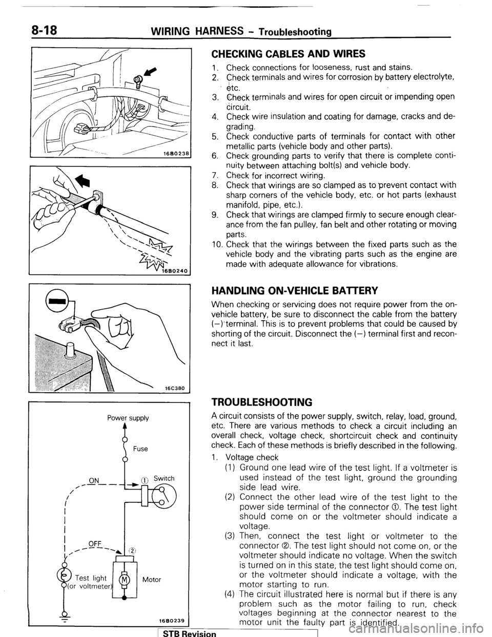
1. Voltage check
(1) Ground one lead wire of the test light. If a voltmeter is
used instead of the test light, ground the grounding
side lead wire.
(2) Connect the other lead wire of the test light to the
power side terminal of the connector 0. The test light
should come on or the voltmeter should indicate a
voltage.
(3) Then, connect the test light or voltmeter to the
connector (3,. The test light should not come on, or the
voltmeter should indicate no voltage. When the switch
is turned on in this state, the test light should come on,
or the voltmeter should indicate a voltage, with the
motor starting to run.
(4) The circuit illustrated here is normal but if there is any
problem such as the motor failing to run, check
voltages beginning at the connector nearest to the
motor unit the faulty part is identified. 1 ST6 Revision
Page 39 of 284
WIRING HARNESS - Troubleshooting 8-19
Test
light Power supply
Fuse block
(remove fuse)
r’TJ Switch
?
Illumination light
4, 1680241
Self power test light Switch
ON
OFF
1680242
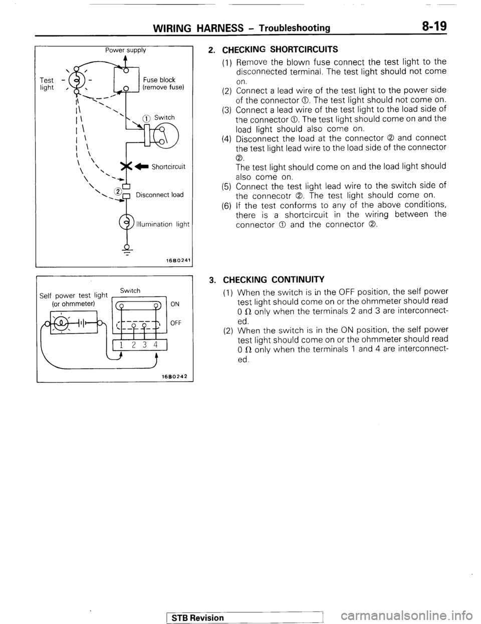
2. CHECKING SHORTCIRCUITS
(1) Remove the blown fuse connect the test light to the
disconnected terminal. The test light should not come
on.
(2) Connect a lead wire of the test light to the power side
of the connector 0. The test light should not come on.
(3) Connect a lead wire of the test light to the load side of
the connector 0. The test light should come on and the
load light should also come on.
(4) Disconnect the load at the connector 0 and connect
the test light lead wire to the load side of the connector
CD.
The test light should come on and the load light should
also come on.
(5) Connect the test light lead wire to the switch side of
the connecotr 0. The test light should come on.
(6) If the test conforms to any of the above conditions,
there is a shortcircuit in the wiring between the
connector 0 and the connector 0.
3. CHECKING CONTINUITY
(I) When the switch is in the OFF position, the self power
test light should come on or the ohmmeter should read
0 R only when the terminals 2 and 3 are interconnect-
ed.
(2) When the switch is in the ON position, the self power
test light should come on or the ohmmeter should read
0 LR only when the terminals 1 and 4 are interconnect-
ed.
) STB Revision
Page 40 of 284
8-20 WIRING HARNESS - How to Read Wiring Diagrams
HOW TO READ WIRING DIAGRAM NOEDBAE
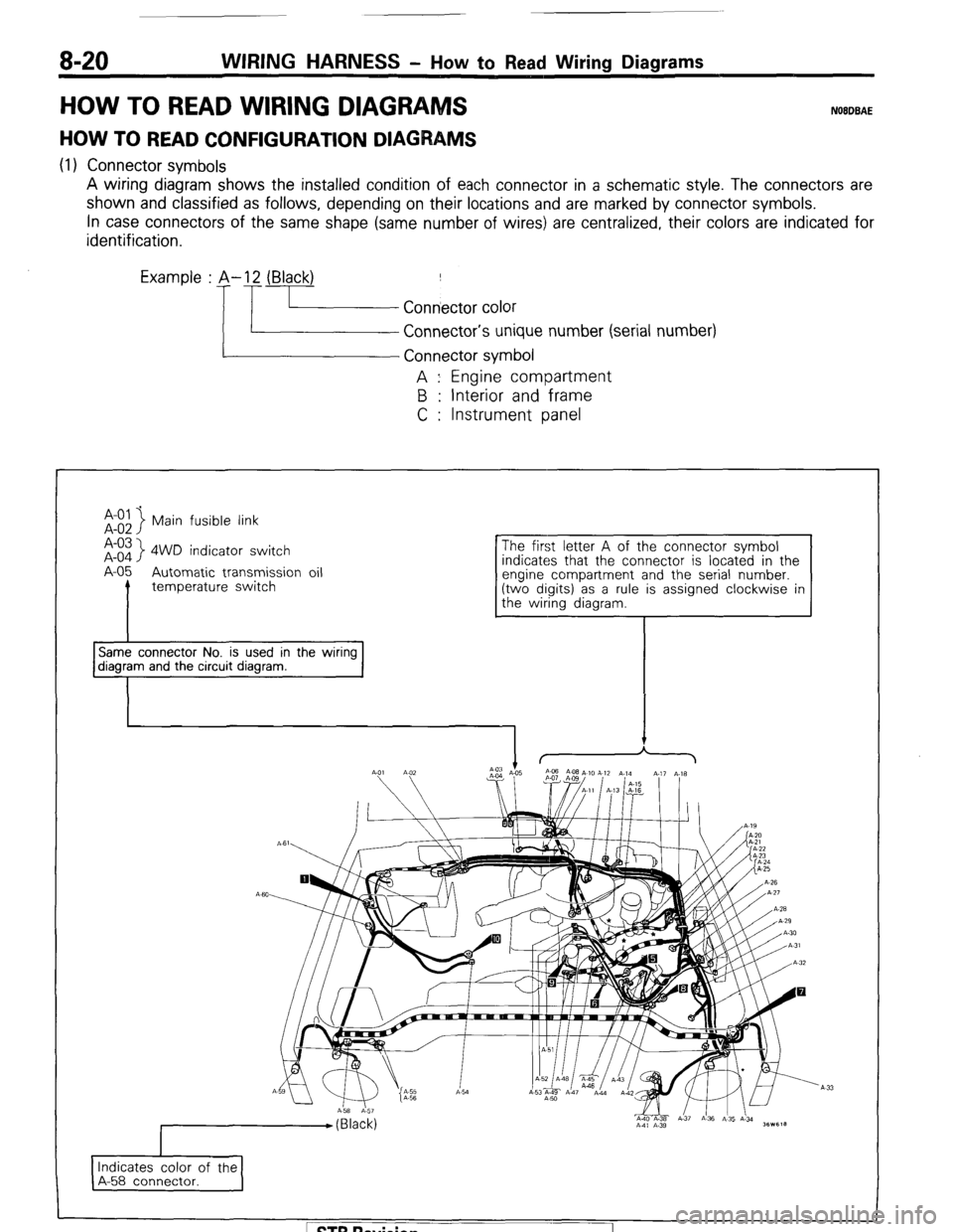
HOW TO READ CONFIGURATION DIAGRAMS
(1) Connector symbols
A wiring diagram shows the installed condition of each connector in a schematic style. The connectors are
shown and classified as follows, depending on their locations and are marked by connector symbols.
In case connectors of the same shape (same number of wires) are centralized, their colors are indicated for
identification.
Examp’e : p.!- f.~~~~ ~;~~o,
Connector’s unique number (serial number)
A : Engine compartment
B : Interior and frame
C : Instrument panel
Main fusible link
A-03
A-o4
> 4WD indicator switch
A-05 Automatic transmission oil
I temperature switch indicates that the connector is located in the
Same connector No. is used in the wiring diagram and the circuit diagram.
I Indicates color of the
A-58 connector. I
1 ST6 Revision