service MITSUBISHI MONTERO 1987 1.G Workshop Manual
[x] Cancel search | Manufacturer: MITSUBISHI, Model Year: 1987, Model line: MONTERO, Model: MITSUBISHI MONTERO 1987 1.GPages: 284, PDF Size: 14.74 MB
Page 1 of 284
Service Manual
MONTERO
1987 : Volume 2
FOREWORD
This Service Manual has been prepared with the
latest service information available at the time of
publication. It is subdivided into various group
categories and each section contains diagnosis,
disassembly, repair, and installation procedures
along with complete specifications and tightening
references. Use of this manual will aid in properly
performing any servicing necessary to maintain or
restore the high levels of performance and reliability
designed into these outstanding vehicles.
WE SUPPORT
VOLUNTARY TECHNICIAN
CERTIFICATION THROUGH
MITSUBISHI MOTOR SALES OF AMERICA. Inc.
Mitsubishi Motors corporation reserves the right to make changes in
design or to make additions to or improvements in its products without
imposing any obligations upon itself to install them on its products
previously manufactured.
I
GROUP/SECTION INDEX ‘kme-.
INTRODUCTION ..............................
Electrical ...........................................
Electrical System Parts
Location .........................................
Relays, Control Units, Sensors,
Fuses, Groundings
Inspection of Harness
Connector ......................................
Wiring Harness .............................
Charging System ..........................
Starting System ............................
Ignition System .............................
Meters and Gauges ......................
Lighting System .............................
Wiper and Washer System ..........
Horn ...............................................
Accessory ......................................
Audio System ................................
Back Door Window Defogger ......
Automatic Free-wheeling Hub
Indicator System ..........................
Heaters and Air-conditioning .........
Heaters ..........................................
Air-conditioning ............................
**, For Engine Chassis & Body refer to
0 1986 Mitsubishi Motors Corporation Printed in Japan
Page 2 of 284
2 INTRODUCTION - How To Use This Manual
HOW TO USE THIS MANUAL NOOBAAK
CONTENTS
The preceding page contains the GROUP INDEX
which lists the group title and group number.
PAGE NUMBERS
All page numbers consist of two sets of digits
separated by a dash. The digits preceding the dash
identify the number of the group. The digits follow-
ing the dash represent the consecutive page
number within the group. The page numbers can
be found on the top left or right of each page.
TEXT
Unless otherwise specified, each service procedure
covers all models. Procedures covering specific
models are identified by the model codes, or similar
designation (engine type, transmission type, etc.).
A description of these designations is covered in
this unit under “VEHICLE IDENTIFICATION”.
SERVICE PROCEDURES
The service steps are arranged in numerical order
and attentions to be paid in performing vehicle ser-
vice are described in detail in SERVICE POINTS.
DEFINITION OF TERMS
STANDARD VALUE
Indicates the value used as the standard for judging
the quality of a part or assembly on inspection or the
value to which the part or assembly is corrected and
adjusted. It is given by tolerance.
LIMIT
Shows the standard for judging the quality of a part
or assembly on inspection and means the maximum
or minimum value within which the part or assembly
must be kept functionally or in strength. It is a value
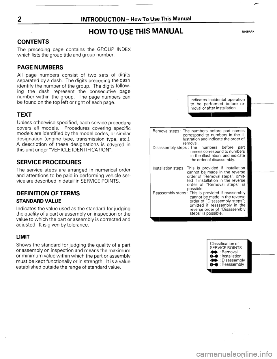
established outside the range of standard value. Installation steps
Indicates incidental operation
piiiKL=l-
Removal steps : The numbers before part names
correspond to numbers in the il-
lustration and indicate the order of
removal.
Disassembly steps : The numbers before part
names correspond to numbers
in the illustration, and indicate
the order of disassembly.
This is provided if installation
cannot be made in the reverse
order of “Removal steps”; omit-
ted if installation in the reverse
order of “Removal steps” is
possible.
.
Reassembly steps : I his IS provided It reassembly
cannot be made in the reverse
order of “Disassembly steps”;
omitted if reassembly in the
reverse order of “Disassembly
steps” is possible.
Classification of
SERVICE ROINTS
Oe : Removal
** : Installation
Oe : Disassembly
I)+ : Reassembly
Page 3 of 284
INTRODUCTION - H
ow To Use This Manual 3
-L
!
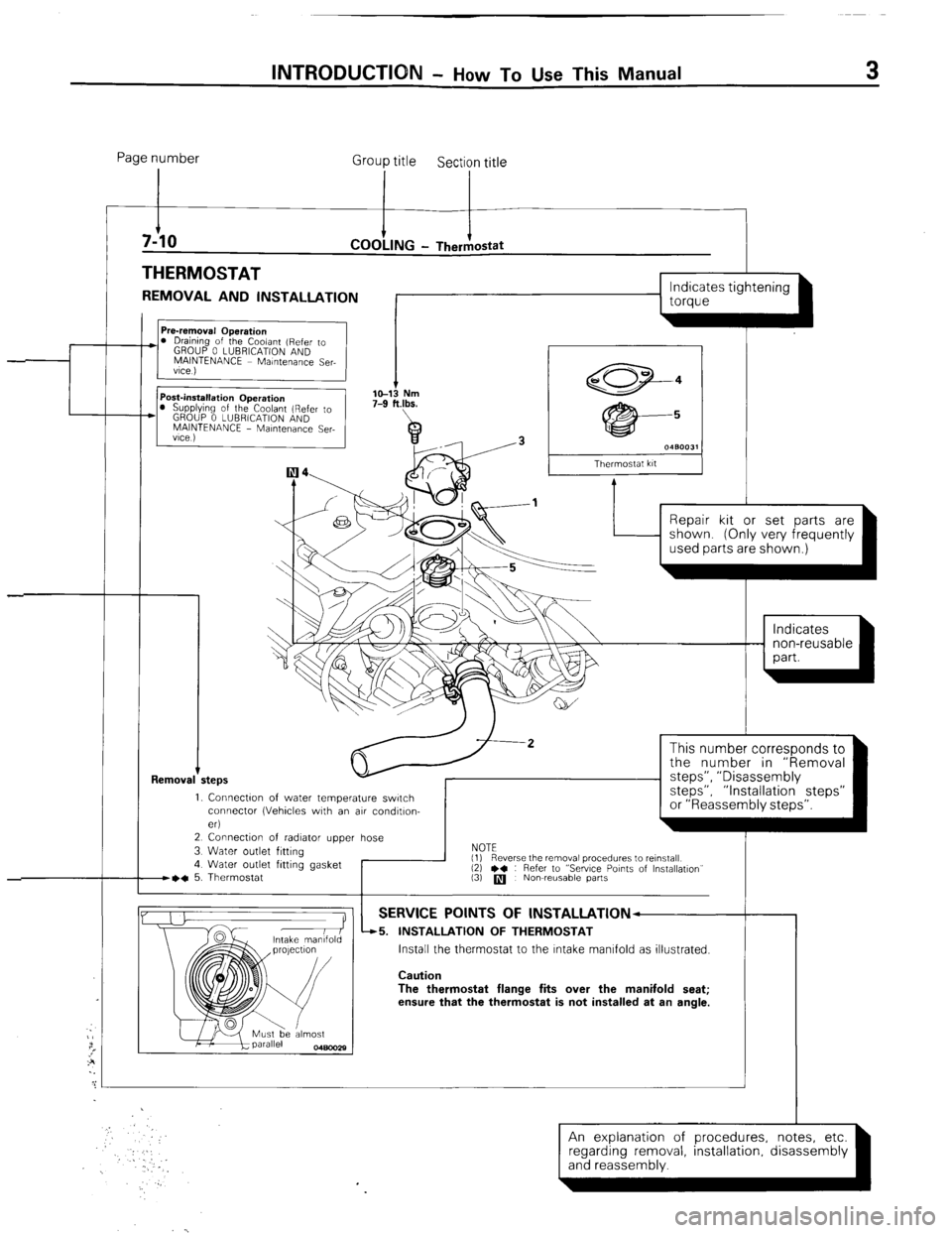
Page number
Group title
Section title
THERMOSTAT
REMOVAL AND INSTALLATION
I
I I
L
1 torque
Removal +
I s 0480031
Thermostat kit
Repair kit or set parts are
1. Connectw of water temperature switch
connector (Vehicles with an air condltlon-
eri
2 Connection of radiator upper hose
3 Water outlet fitting
4 Water outlet fitting gasket
B~C 5. Thermostat I
This number corresponds to
the number in “Removal
steps”, ” Disassembly
steps”, “Installation steps”
or “Reassembly steps”.
NOTE
(1)
(3)
q Nowreusable parts
-r Reverse the removal procedures to reinstall
12) l * : Refer to “Sewce Points of Installation”
SERVICE POINTS OF lNSTALLATlON--
45. INSTALLATION OF THERMOSTAT
Install the thermostat to the Intake manifold as illustrated.
Caution
The thermostat flange fits over the manifold seat;
ensure that the thermostat is not installed at an angle.
An explanation of procedures, notes, etc.
(and reassembly. ’ ’ -1 regarding removal installation disassembly
Page 8 of 284
8 INTRODUCTION - Precautions Before Service
r oorn,
FOOOl;
FOOOl8
PRECAUTIONS BEFORE SERVICE
PROTECTIN” THE VEHICLE NOODAAC
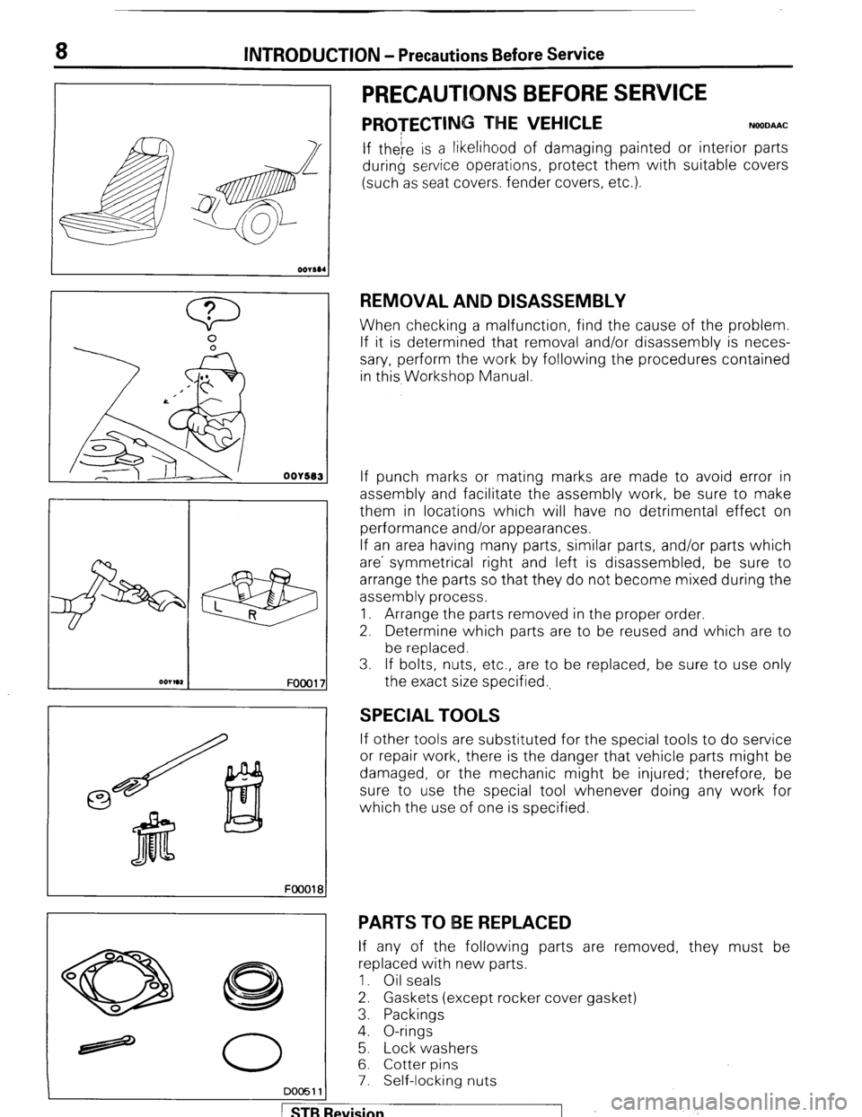
If theIre is a likelihood of damaging painted or interior parts
during service operations, protect them with suitable covers
(such as seat covers. fender covers, etc.).
REMOVAL AND DISASSEMBLY
When checking a malfunction, find the cause of the problem.
If it is determined that removal and/or disassembly is neces-
sary, perform the work by following the procedures contained
in this, Workshop Manual.
If punch marks or mating marks are made to avoid error in
assembly and facilitate the assembly work, be sure to make
them in locations which will have no detrimental effect on
performance and/or appearances.
If an area having many parts, similar parts, and/or parts which
are’ symmetrical right and left is disassembled, be sure to
arrange the parts so that they do not become mixed during the
assembly process.
1. Arrange the parts removed in the proper order.
2. Determine which parts are to be reused and which are to
be replaced.
3. If bolts, nuts, etc., are to be replaced, be sure to use only
the exact size specified.,
SPECIAL TOOLS
If other tools are substituted for the special tools to do service
or repair work, there is the danger that vehicle parts might be
damaged, or the mechanic might be injured; therefore, be
sure to use the special tool whenever doing any work for
which the use of one is specified.
PARTS TO IBE REPLACED
If any of the following parts are removed, they must be
replaced with new parts.
1. Oil seals
2. Gaskets (except rocker cover gasket)
3. Packings
4. O-rings
5. Lock washers
6. Cotter pins
7. Self-locking nuts
DO05111
STB Revision ,j .’
Page 9 of 284
INTRODUCTION - Precautions Before Service 9
nm (in.)
so0059
PARTS
When replacing parts, use MITSUBISHI genuine parts.
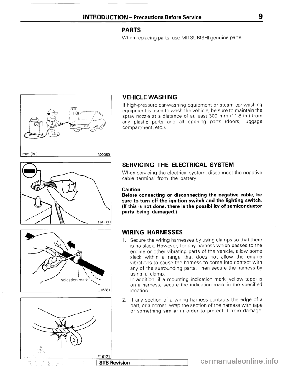
VEHICLE WVASHING
If high-pressure car-washing equipment or steam car-washing
equipment is used to wash the vehicle, be sure to maintain the
spray nozzle at a distance of at least 300 mm (1 1.8 in.) from
any plastic parts and all opening parts (doors, luggage
compartment, etc.).
SERVICING THE ELECTRICAL SYSTEM
When servicing the electrical system, disconnect the negative
cable terminal from the battery.
Caution
Before connecting or disconnecting the negative cable, be
sure to turn off the ignition switch and the lighting switch.
(If this is not done, there is the possibility of semiconductor
parts being damaged.)
WIRING HARNESSES
1. Secure the wiring harnesses by using clamps so that there
is no slack. However, for any harness which passes to the
engine or other vibrating parts of the vehicle, allow some
slack within a range that does not allow the engine
vibrations to cause the harness to come into contact with
any of the surrounding parts. Then secure the harness by
using a clamp.
In addition, if a mounting indication mark (yellow tape) is
on a harness, secure the indication mark in the specified
location.
2. If any section of a wiring harness contacts the edge of a
part, or a corner, wrap the section of the harness with tape
or something similar in order to protect it from damage.
F161711
* :, :, 1 STB Revision
Page 10 of 284
INTRODUCTION - Precautions Before Service
16Rl263
16R1264 Y16347
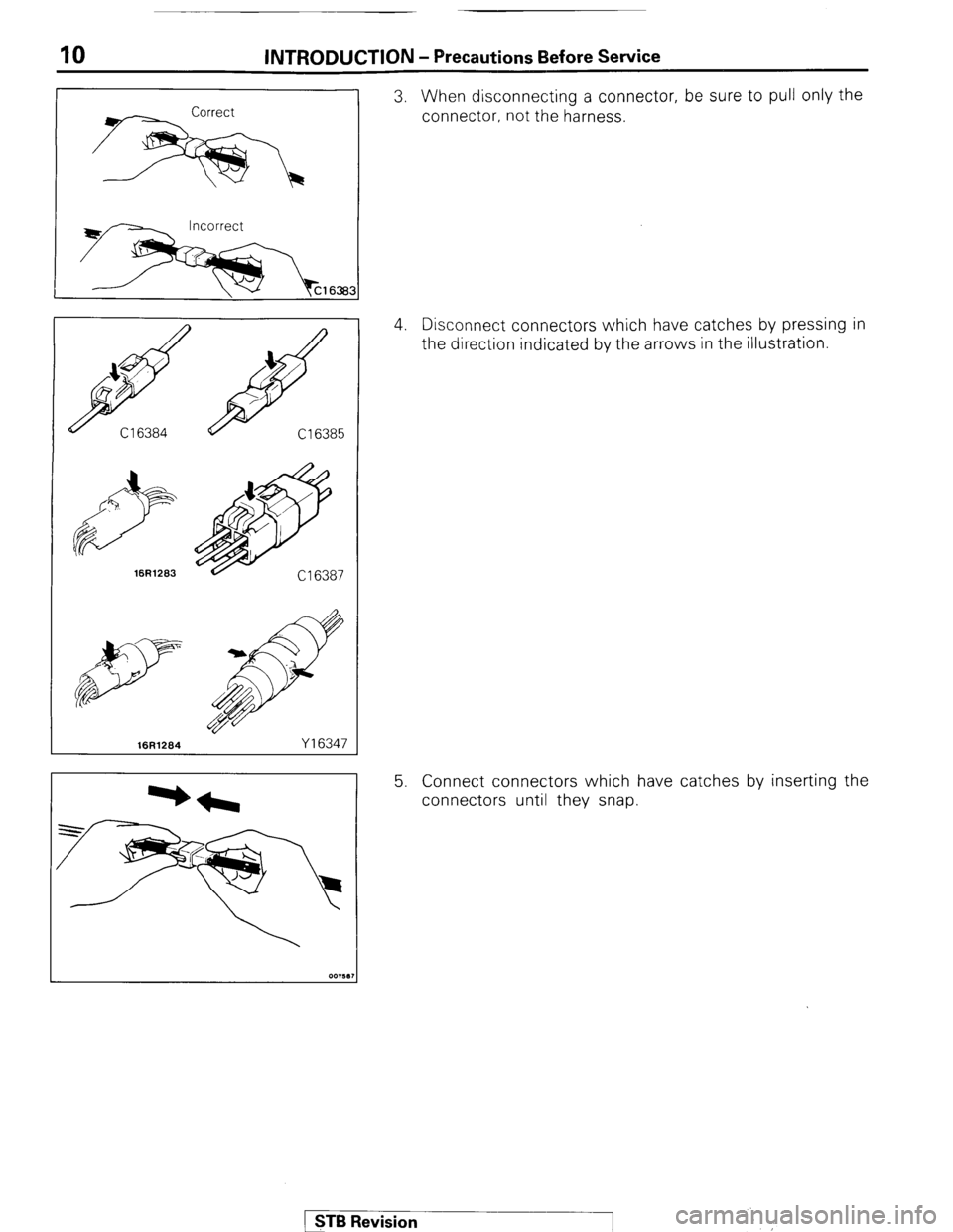
3. When disconnecting a connector, be sure to pull only the
connector, not the harness.
4. Disconnect connectors which have catches by pressing in
the direction indicated by the arrows in the illustration.
5. Connect connectors which have catches by inserting the
connectors until they snap.
( STB Revision
‘.
Page 11 of 284
INTRODUCTION - Precautions Before Service 11
I
OOY63:
oOY58S IOA 15A
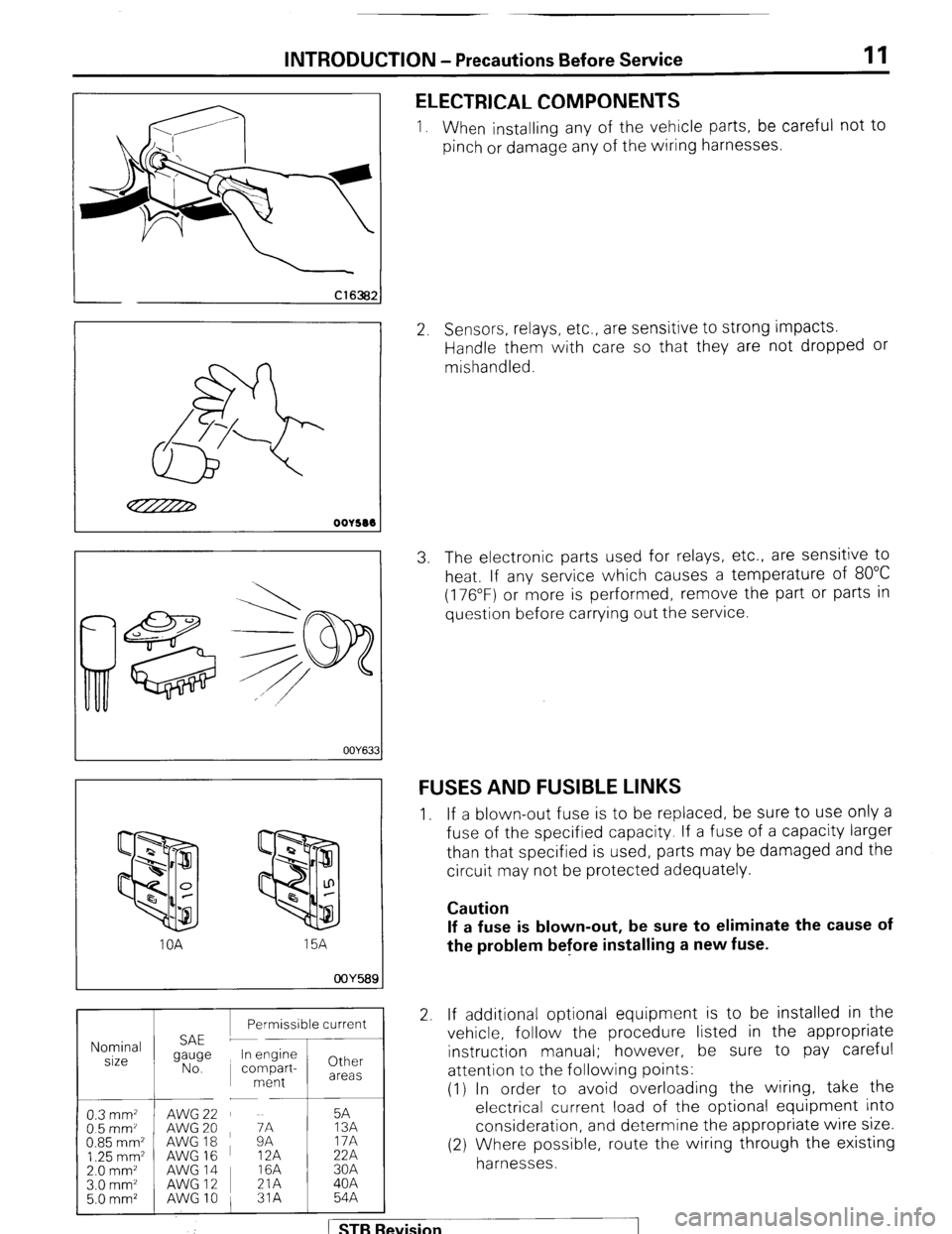
1 Permissible current 1
Nominal
size
0.3 mm2 AWG22 5A
05mm’ AWG 20
AWG18 ~ zi 13A
0.85 mm2 17A
1.25 mm2 AWG 16 12A 22A
2.0 mm2 AWG14 I 16A 30A
ELECTRICAL COMPONENTS
1. When installing any of the vehicle parts, be careful not to
pinch or damage any of the wiring harnesses.
2. Sensors, relays, etc., are sensitive to strong impacts.
Handle them with care so that they are not dropped or
mishandled.
3. The electronic parts used for relays, etc., are sensitive to
heat, If any service which causes a temperature of 80°C
(176°F) or more is performed, remove the part or parts in
question before carrying out the service.
FUSES AND FUSIBLE LINKS
1. If a blown-out fuse is to be replaced, be sure to use only a
fuse of the specified capacity. If a fuse of a capacity larger
than that specified is used, parts may be damaged and the
circuit may not be protected adequately.
Caution
If a fuse is blown-out, be sure to eliminate the cause of
the problem before installing a new fuse.
2 If additional optional equipment is to be installed in the
vehicle, follow the procedure listed in the appropriate
instruction manual; however, be sure to pay careful
attention to the following points:
(1) In order to avoid overloading the wiring, take the
electrical current load of the optional equipment into
consideration, and determine the appropriate wire size.
(2) Where possible, route the wiring through the existing
harnesses.
I Revision
Page 12 of 284
12 INTRODUCTION - Precautions Before Service
(3) If an ammeter or similar instrument is to be connected
to a live-wire circuit, use tape to protect the wire, use a
i clamp to secure the wire, and make sure that there is
, no contact with any other parts.
(4’) Be sure to provide a fuse for the load circuit of the
optional equipment.
FooO281
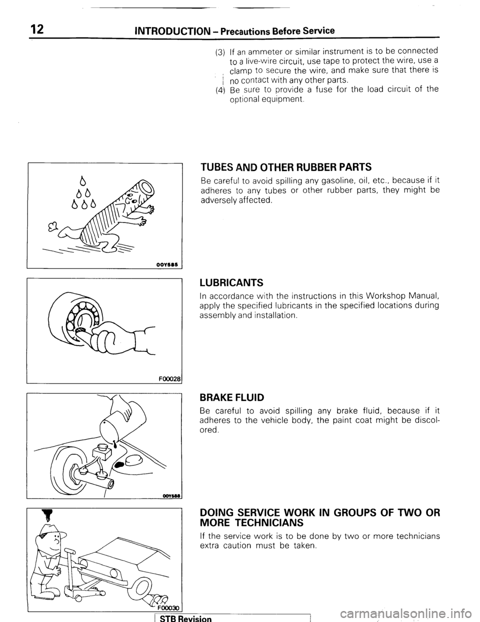
TUBES AND OTHER RUBBER PARTS
Be careful to avoid spilling any gasoline, oil, etc.. because if it
adheres to any tubes or other rubber parts, they might be
adversely affected.
LUBRICANTS
In accordance with the instructions in this Workshop Manual,
apply the specified lubricants in the specified locations during
assembly and installation.
BRAKE FLUID
Be careful to avoid spilling any brake fluid, because if it
adheres to the vehicle body, the paint coat might be discol-
ored.
DOING SERVICE WORK IN GROUPS OF TWO OR
MORE TECHNICIANS
If the service work is to be done by two or more technicians
extra caution must be taken.
-FOOO3OI
1 STB Revision ’
:
Page 13 of 284
INTRODUCTION - Precautions Before Service 13
IKITE ON INSTALLATION OF RADIO EQUIPMW&
The computers of the electronic control system has been
designed so that external radio waves will not interfere with
their operation.
However, if antenna or cable of amateur transceiver etc. is
routed near the computers, it may affect the operation of the
computers, even if the output of the transceiver is no more
than 25W.
To protect each of the computers from interference by
transmitter (hum, transceiver, etc.), the following should be
observed.
1. Install the antenna on the roof.
2. Because radio waves are emitted from the coaxial cable of
the antenna, keep it 200 mm (8 in.) away from the
computers and the wiring harness. If the cable must cross
the wiring harness, route it so that it runs at right angles to
the wiring harness.
3. The antenna and the cable should be well matched, and
the standing-wave ratio* should be kept low.
4. A transmitter having a large output should not be installed
in the vehicle.
5. After installation of transmitter, run the engine at idle, emit
radio waves from the transmitter and make sure that the
engine is not affected.
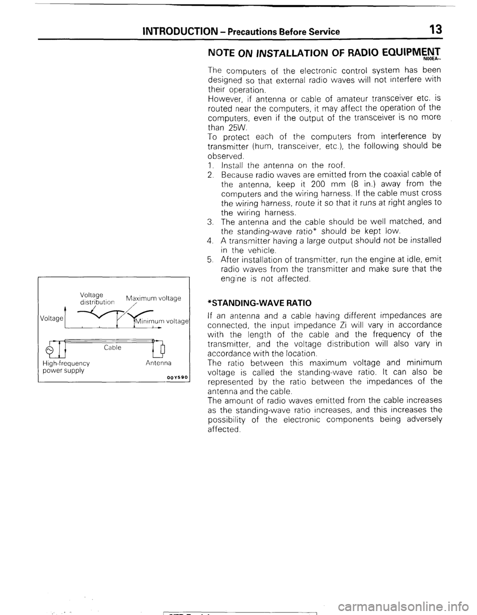
High-frequency power supply If an antenna and a cable having different impedances are
connected, the input impedance Zi will vary in accordance
with the length of the cable and the frequency of the
transmitter, and the voltage distribution will also vary in
accordance with the location.
The ratio between this maximum voltage and minimum
voltage is called the standing-wave ratio. It can also be
represented by the ratio between the impedances of the
antenna and the cable.
The amount of radio waves emitted from the cable increases
as the standing-wave ratio increases, and this increases the
possibility of the electronic components being adversely
affected.
_. r.
; ST6 Revision
Page 15 of 284
INTRODUCTION - Towing and Hoisting
HOISTING
POST TYPE
15
Special care should be taken when raising the vehicle on a
frame contact type hoist. The hoist must be equipped with the
proper adapters in order to support the vehicle at the proper
locations. (See next page)
Conventional hydraulic hoists may be used after determining
that the adapter plates will make firm contact with the side
frame.
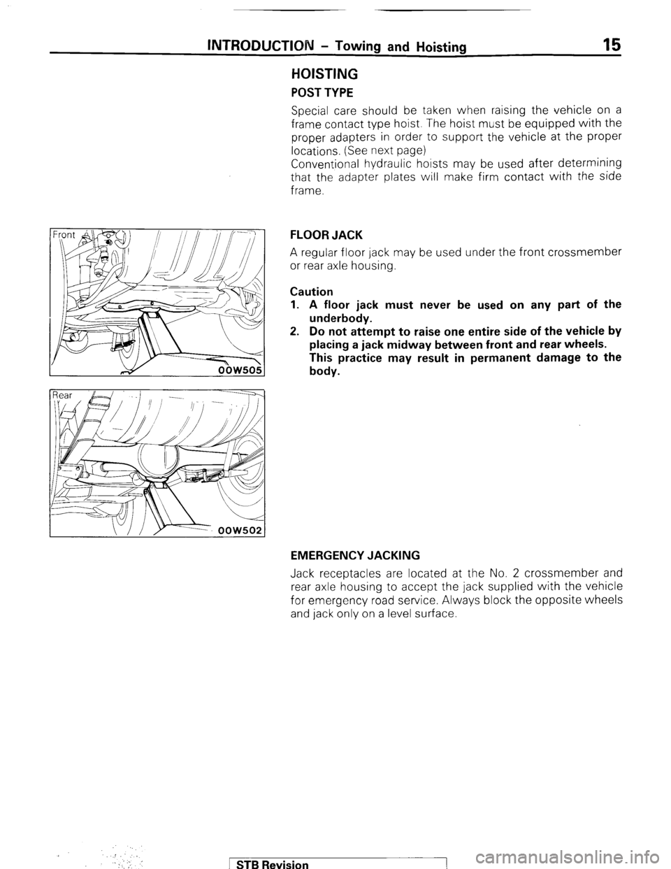
FLOOR JACK
A regular floor jack may be used under the front crossmember
or rear axle housing.
Caution
1. A floor jack must never be used on any part of the
underbody.
2. Do not attempt to raise one entire side of the vehicle by
placing a jack midway between front and rear wheels.
This practice may result in permanent damage to the
body.
EMERGENCY JACKING
Jack receptacles are located at the No. 2 crossmember and
rear axle housing to accept the jack supplied with the vehicle
for emergency road service. Always block the opposite wheels
and jack only on a level surface.
.::
. Y!’ ,,. I
.I
‘.
1 STB Revision