light MITSUBISHI MONTERO 1987 1.G Repair Manual
[x] Cancel search | Manufacturer: MITSUBISHI, Model Year: 1987, Model line: MONTERO, Model: MITSUBISHI MONTERO 1987 1.GPages: 284, PDF Size: 14.74 MB
Page 86 of 284
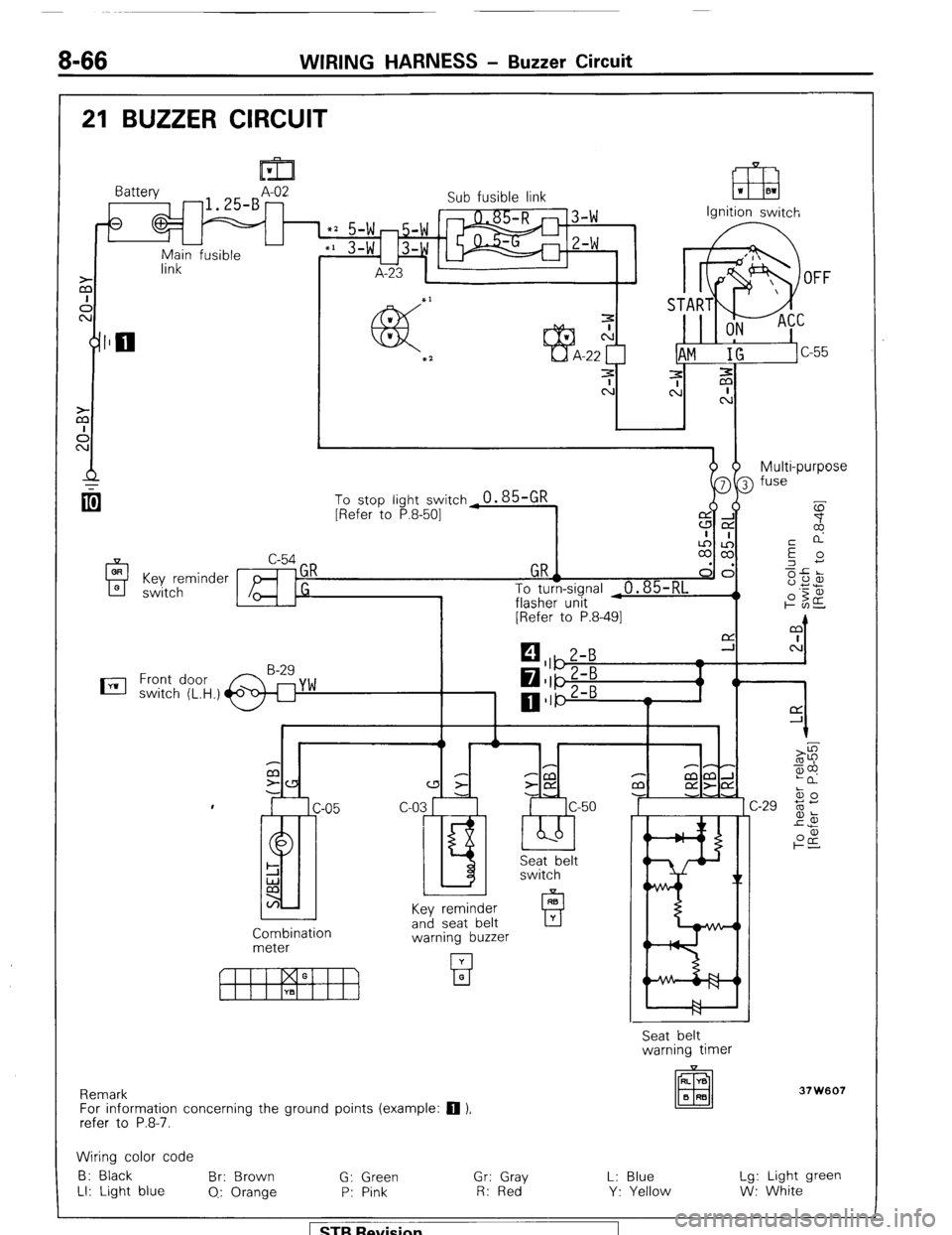
8-66 WIRING HARNESS - Buzzer Circuit
21 BUZZER CIRCUIT
OR
A 0 Key reminder
switch
nil 1
link Battery A-02
-1.25-B -
0
-
Main fusible Sub fusible link
IT8 ‘I 01
Ignition switch
dhm b- Multi-purpose
[Refer to P.8-491
0 1
C P-P
a 3
-CCl P mm-l
z- z-CY m aa-cd
c-03 r c-50 -J -.A
I.5 ‘bb’ IC ski&t
switch
Key reminder
Combination
meter and seat belt
warning buzzer
Remark
For information concerning the ground points (example:
q ),
refer to P.8-7. Seat belt
warning timer
37W607
Wiring color code
B: Black Br: Brown
G: Green Gr: Gray L: Blue Lg: Light green
LI: Light blue
0.: Orange P: Pink R: Red Y: Yellow W: White 1 ST9 Revision
Page 87 of 284
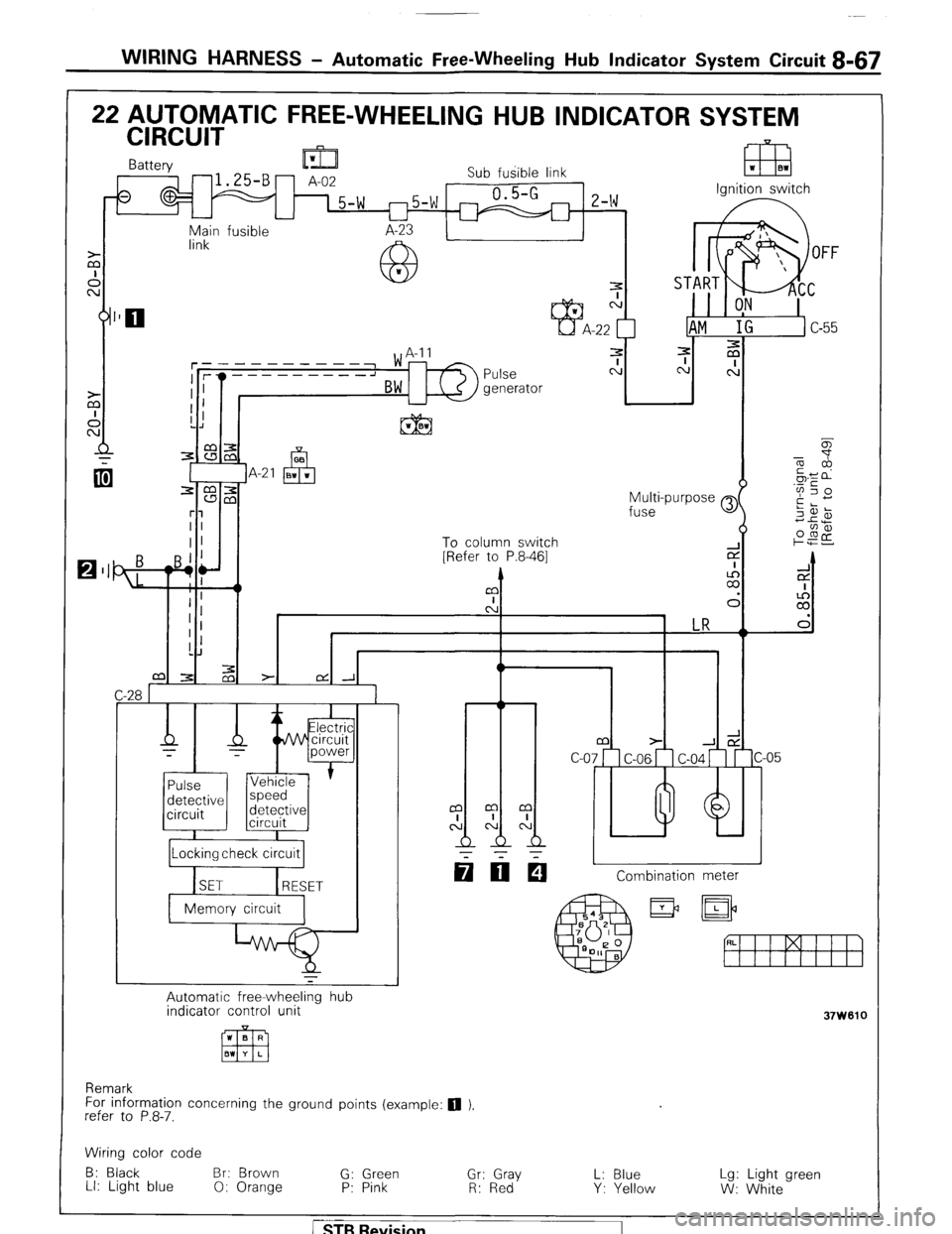
WIRING HARNESS - Automatic Free-Wheeling Hub Indicator System Circuit B-67
FREE-WHEELING HUB INDICATOR SYSTFM
Sub fusible link
-5-w 1 m2-G m Iz-w rgntrron swrtcn Battery n 171.
Main fusible
link
- _I
ON I
Pulse
generator
-
Multi-purpose e
fuse
To column switch
[Refer to P.8-461 z
1
m ::
0:
C
1 LR
I
1
I
0
2-
I I
!!I m m m
,:cAcJl
-
T-r- m z-
-.I;
c-07 C-06 c-04
I++-
q OE! L 1 Combination meter ’ EleAtrir
d&V+ circuit
- -
power
1
Pulse Vehicle
detective speed
circuit detective
circuit
r
Automatic free-wheeling hub
indicator control unit
37W610
For information concerning the ground points (example: 0 ).
refer to P.8-7.
Wiring color code
B: Black Br: Brown
G: Green
L: Blue
LI: Light blue
0: Orange “,;: ;;;Y Lg: Light green
P: Pink Y: Yellow
W: White
STB Revision
Page 88 of 284
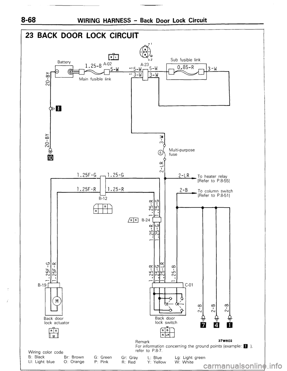
WIRING HARNESS - Back Door Lock Circuit
23 BACK DOOR LOCK CIRCUIT
Battery _ Sub fusible link
$’
m 5 Multi-purpose ’
fuse
)
A 1.25F-G -1.25-G
0 2-LR -To heater relay
[Refer to P.8-551
1.25F-R 1.25-R
2-B -To column switch
B-l 2 [Refer to P.8-511
cza
I I
xx 0
I
. .
77
m B-24 [
cLL3
ALA
CVN
. .
77
Back door
lock actuator
Remark
37W602
For information concerning the ground points (example: q ),
Wiring color code refer to P.8-7.
B: Black
Br: Brown G: Green
Gr: Gray L: Blue Lg: Light green
LI: Light blue 0: Orange P: Pink
R: Red Y: Yellow W: White
/ STB Revision
Page 89 of 284
WIRING HARNESS - Centralized Junction
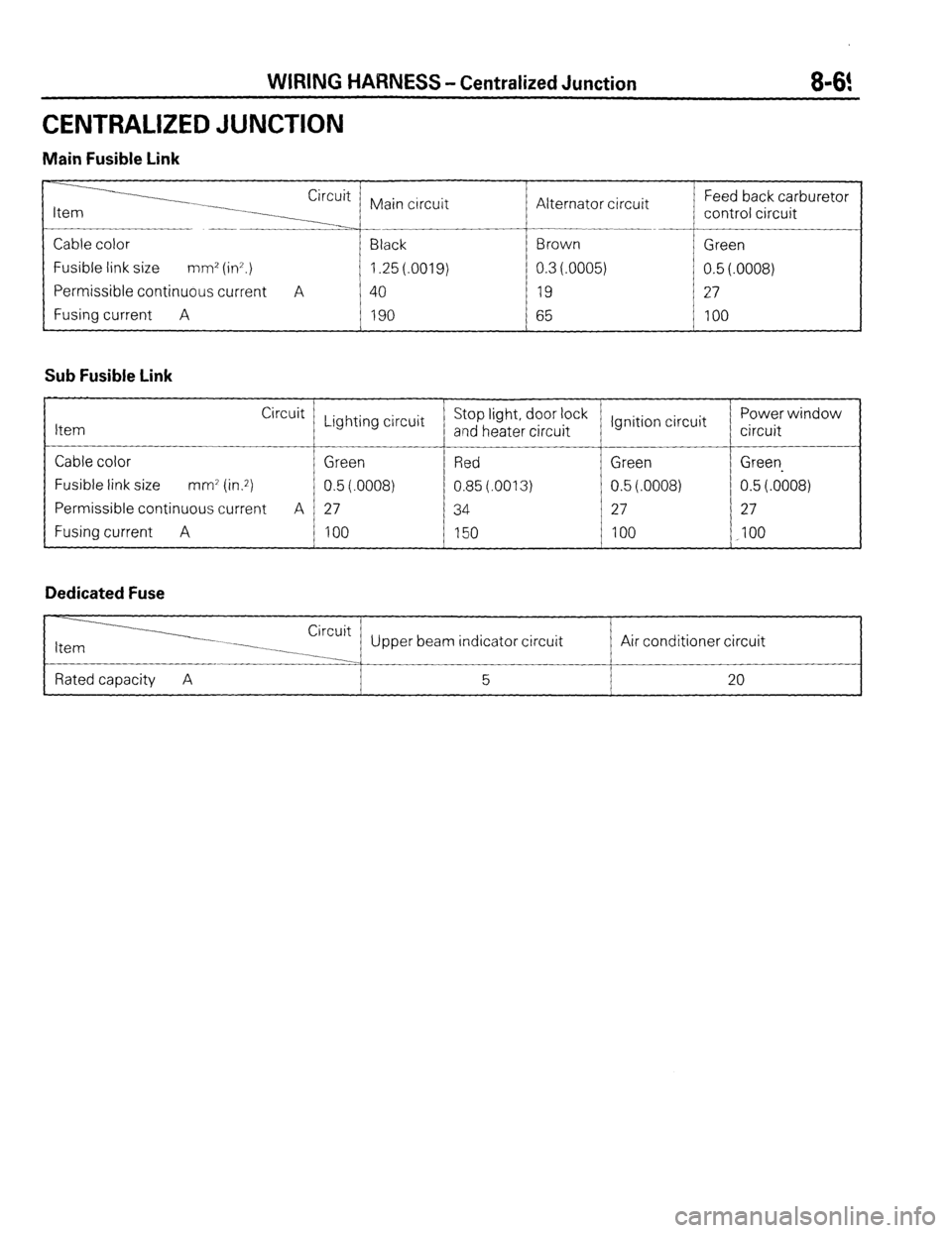
CENTRALIZED JUNCTION
Main Fusible Link
896!
Circuit
Main circuit
Cable color Black
Fusible link size mm’ (ir?.) 1.25 (.0019)
Permissible continuous current A 40
Fusing current A 190
Sub Fusible Link
Item Circuit
Cable color
Fusible link size mm7 (in.2)
Permissible continuous current A
Fusing current A
Dedicated Fuse Lighting circuit
Green
0.5(.0008)
27
100 Alternator circuit Feed back carburetor
control circuit
Stop light, door lock
and heater circuit
Red
0.85(.0013)
34
150 Ignition circuit Power window
circuit
Green Green-
0.5(.0008) 0.5(.0008)
27 27
100 100
Upper beam indicator circuit / Air conditioner cixit
Page 90 of 284
WIRING HARNESS - Centralized Junction
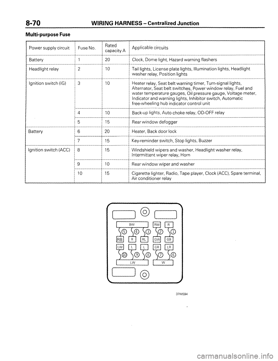
Multi-purpose Fuse
Power supply circuit Fuse No. Rated
capacity A Applicable circuits
Battery 1 20
Clock, Dome light, Hazard warning flashers
Headlight relay 2 10 Tail lights, License plate lights, Illumination lights, Headlight
washer relay, Position lights
__-
Ignition switch (IG) 3 10 Heater relay, Seat belt warning timer, Turn-signal lights,
Alternator, Seat belt switches, Power window relay, Fuel and
water temperature gauges, Oil pressure gauge, Voltage meter,
Indicator and warning lights, Inhibitor switch, Automatic
free-wheeling hub indicator control unit
4
IO Back-up lights, Auto choke relay, OD-OFF relay
__-
5 15 Rear window defogger
Battery 6 20 Heater, Back door lock
7 15 Key-reminder switch, Stop lights, Buzzer
Ignition switch (ACC) 8 15 Windshield wipers and washer, Headlight washer relay,
Intermittent wiper relay, Horn
9 10 Rear window wiper and washer
10 15 Cigarette lighter, Radio, Tape player, Clock (ACC), Spare terminal,
Air conditioner relay
Page 91 of 284
CHARGING SYSTEM - General Information 8-71
CHARGING SYSTEM
GENERAL INFORMATION
NOBEMD
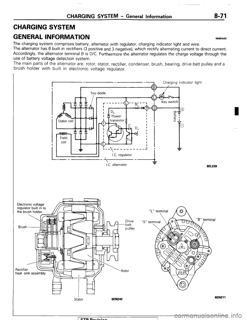
The charging system comprises battery, alternator with regulator, charging indicator light and wire.
The alternator has 6 built in rectifiers (3 positive and 3 negative), which rectify alternating current to direct current.
Accordingly, the alternator terminal B is D/C. Furthermore the alternator regulates the charge voltage through the
use of battery voltage detection system.
The main parts of the alternator are: rotor, stator, rectifier, condenser, brush, bearing, drive belt pulley and a
brush holder with built in electronic voltage regulator.
:--\;-----------I ;
I.C. regulator
I
-A I.C. alternator -y
Brush
heat -sink assembly Drive
-belt
pulley
Rotor light
6EL239
Stator 6EN246 6EN211
1 STB Revision
Page 95 of 284
CHARGING SYSTEM -Troubleshooting 8-75
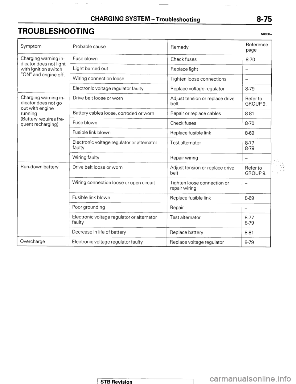
TROUBLESHOOTING
NOBEH-
Symptom Probable cause
Remedy Reference
we
Charging warning in- Fuse blown
dicator does not light
with ignition switch Light burned out
“ON” and engine off. 1
1 Wiring connection loose Check fuses
Replace light
Tighten loose connections 8-70
-
-
Charging warning in-
dicator does not go
out with engine
running
(Battery requires fre-
quent recharging)
L
t
Run-down battery
c
Electronic voltage regulator faulty
Drive belt loose or worn
Battery cables loose, corroded or worn
Fuse blown
Fusible link blown
Electronic voltage regulator or alternator
faulty
Wiring faulty
Drive belt loose or worn
Wiring connection loose or open circuit
Fusible link blown Replace voltage regulator
Adjust tension or replace drive
belt
Repair or replace cables
Check fuses
Replace fusible link
Test alternator
Repair wiring
Adjust tension or replace drive
belt
Tighten loose connection or
repair wiring
Replace fusible link 8-79
Refer to
GROUPS.
8-8 1
8-70
8-69
8-77
8-79
-
Refer to
GROUP 9.
-
8-69
Poor grounding 1 Repair
I-
I I I Electronic voltage regulator or alternator
faulty Test alternator 8-77
8-79
Overcharge Decrease in life of battery
Replace battery
8-81 I
Electronic voltage regulator faulty Replace voltage regulator 8-79
STB Revision
Page 96 of 284
![MITSUBISHI MONTERO 1987 1.G Repair Manual 8-76 CHARGING SYSTEM - Circuit Diagram
3 CHARGING CIRCUIT
Battery Ignition switch
OFF
Main
m fusible ’ L
link
A-02
fl.3-Br 1~5~~
, A-23 Sub fusible link
(IGN . SW)
IAM IG ] c-55
3
3
A MITSUBISHI MONTERO 1987 1.G Repair Manual 8-76 CHARGING SYSTEM - Circuit Diagram
3 CHARGING CIRCUIT
Battery Ignition switch
OFF
Main
m fusible ’ L
link
A-02
fl.3-Br 1~5~~
, A-23 Sub fusible link
(IGN . SW)
IAM IG ] c-55
3
3
A](/img/19/7559/w960_7559-95.png)
8-76 CHARGING SYSTEM - Circuit Diagram
3 CHARGING CIRCUIT
Battery Ignition switch
OFF
Main
m fusible ’ L
link
A-02
fl.3-Br 1~5~~
, A-23 Sub fusible link
(IGN . SW)
IAM IG ] c-55
3
3
A m
A
To turn signal flasher
unit [Refer to P.8-49.1 Multi-
n, Irnn4P
ComSeter
Remark
For information concerning the ground points (example:
q ),
refer to P.8-7. 37W605
Wiring color code
B: Black Br: Brown G: Green Gr: Gray L: Blue Lg: Light green
LI: Light blue 0: Orange P: Pink R: Red Y: Yellow W: White
1 STB Revision
Page 97 of 284
CHARGING SYSTEM - Service Adjustment Procedures 8-77
SERVICE ADJUSTMENT PROCEDUREswmAB
lEL15I
INSPECTION OF THE CHARGING SYSTEM
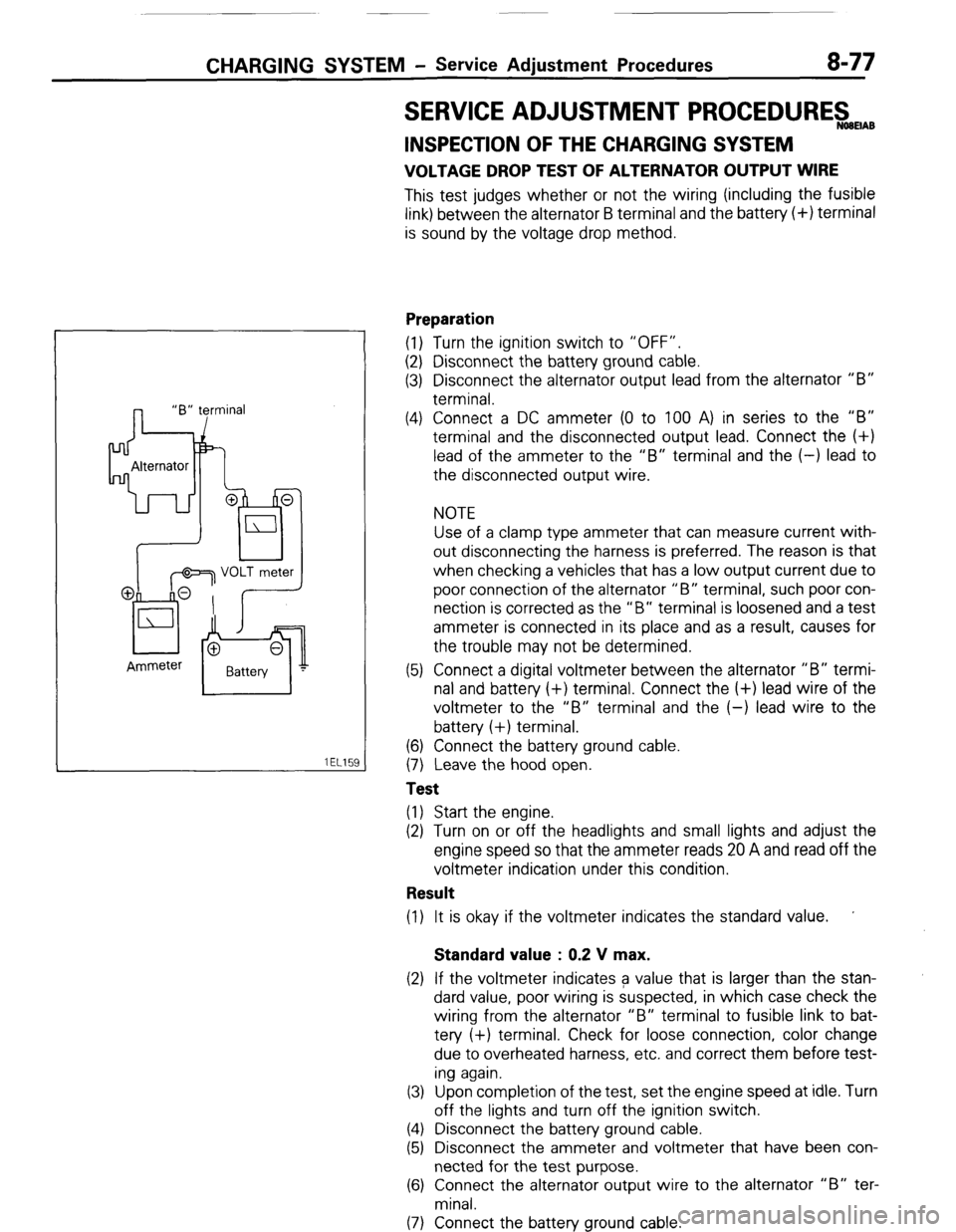
VOLTAGE DROP TEST OF ALTERNATOR OUTPUT WIRE
This test judges whether or not the wiring (including the fusible
link) between the alternator B terminal and the battery (+) terminal
is sound by the voltage drop method.
Preparation
(1) Turn the ignition switch to “OFF”.
(2) Disconnect the battery ground cable.
(3) Disconnect the alternator output lead from the alternator “B”
terminal.
(4) Connect a DC ammeter (0 to 100 A) in series to the “B”
terminal and the disconnected output lead. Connect the (+)
lead of the ammeter to the “B” terminal and the (-) lead to
the disconnected output wire.
NOTE
Use of a clamp type ammeter that can measure current with-
out disconnecting the harness is preferred. The reason is that
when checking a vehicles that has a low output current due to
poor connection of the alternator “B” terminal, such poor con-
nection is corrected as the “B” terminal is loosened and a test
ammeter is connected in its place and as a result, causes for
the trouble may not be determined.
(5) Connect a digital voltmeter between the alternator “B” termi-
nal and battery (+) terminal. Connect the (+) lead wire of the
voltmeter to the “B” terminal and the (-) lead wire to the
battery (+) terminal.
(6) Connect the battery ground cable.
(7) Leave the hood open.
Test
(1) Start the engine.
(2) Turn on or off the headlights and small lights and adjust the
engine speed so that the ammeter reads 20 A and read off the
voltmeter indication under this condition.
Result
(1) It is okay if the voltmeter indicates the standard value. ’
Standard value : 0.2 V max.
(2) If the voltmeter indicates a value that is larger than the stan-
dard value, poor wiring is suspected, in which case check the
wiring from the alternator “B” terminal to fusible link to bat-
tery (+) terminal. Check for loose connection, color change
due to overheated harness, etc. and correct them before test-
ing again.
(3) Upon completion of the test, set the engine speed at idle. Turn
off the lights and turn off the ignition switch.
(4) Disconnect the battery ground cable.
(5) Disconnect the ammeter and voltmeter that have been con-
nected for the test purpose.
(6) Connect the alternator output wire to the alternator “B” ter-
minal.
(7) Connect the battery ground cable.
( STB Revision
Page 98 of 284
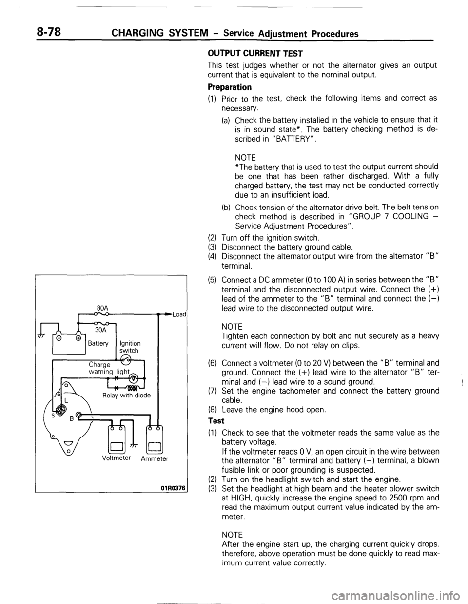
8-78 CHARGING SYSTEM - Service Adiustment Procedures
80A
n
Relay with diode
Voltmeter
Ammeter Iad
176
OUTPUT CURRENT TEST
This test judges whether or not the alternator gives an output
current that is equivalent to the nominal output.
Preparation
(1) Prior to the test, check the following items and correct as
necessary.
(a) Check the battery installed in the vehicle to ensure that it
is in sound state*. The battery checking method is de-
scribed in “BATTERY”.
NOTE
*The battery that is used to test the output current should
be one that has been rather discharged. With a fully
charged battery, the test may not be conducted correctly
due to an insufficient load.
(b) Check tension of the alternator drive belt. The belt tension
check method is described in “GROUP 7 COOLING -
Service Adjustment Procedures”.
(2) Turn off the ignition switch.
(3) Disconnect the battery ground cable.
(4) Disconnect the alternator output wire from the alternator “B”
terminal.
(5) Connect a DC ammeter (0 to 100 A) in series between the “B”
terminal and the disconnected output wire. Connect the (+)
lead of the ammeter to the “B” terminal and connect the (-)
lead wire to the disconnected output wire.
NOTE
Tighten each connection by bolt and nut securely as a heavy
current will flow. Do not relay on clips.
(6) Connect a voltmeter (0 to 20 V) between the “B” terminal and
ground. Connect the (+) lead wire to the alternator “B” ter-
minal and (-) lead wire to a sound ground.
(7) Set the engine tachometer and connect the battery ground
cable.
(8) Leave the engine hood open.
Test
(1) Check to see that the voltmeter reads the same value as the
battery voltage.
If the voltmeter reads 0 V, an open circuit in the wire between
the alternator “B” terminal and battery (-) terminal, a blown
fusible link or poor grounding is suspected.
(2) Turn on the headlight switch and start the engine.
(3) Set the headlight at high beam and the heater blower switch
at HIGH, quickly increase the engine speed to 2500 rpm and
read the maximum output current value indicated by the am-
meter.
NOTE
After the engine start up, the charging current quickly drops.
therefore, above operation must be done quickly to read max-
imum current value correctly.
[ STB Revision
--I