service MITSUBISHI MONTERO 1987 1.G Manual PDF
[x] Cancel search | Manufacturer: MITSUBISHI, Model Year: 1987, Model line: MONTERO, Model: MITSUBISHI MONTERO 1987 1.GPages: 284, PDF Size: 14.74 MB
Page 248 of 284
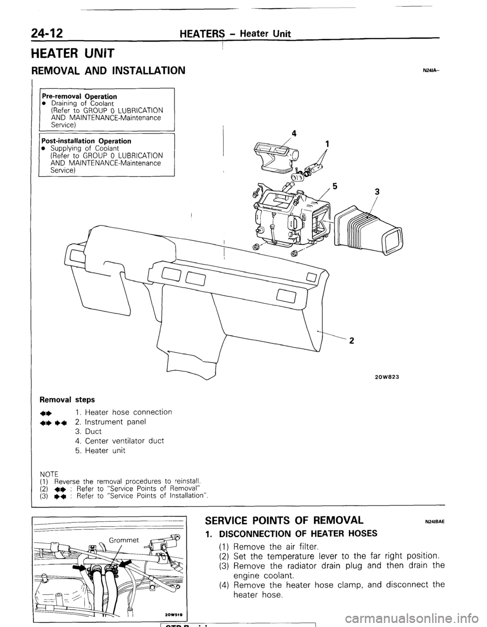
24-12 HEATERS - Heater Unit
I
HEATER UNBT
REMOVAL AND INSTALLATION
Pre-removal Operation
0 Draining of Coolant
(Refer to GROUP 0 LUBRICATION
AND MAINTENANCE-Maintenance
Service)
Post-installation Operation
0 Supplying of Coolant
(Refer to GROUP 0 LUBRICATION
AND MAINTENANCE-Maintenance
Service) Removal steps
l *
I, Heater hose connection
+* l 4
2. Instrument panel
3. Duct
4. Center ventilator duct
5. Heater unit
NOTE
(1) Reverse the removal procedures to reinstall.
(2) +e : Refer to “Service Points of Removal”
(3) l
+ : Refer to “Service Points of Installation”
2OW823
SERVICE POINTS OF REMOVAL
1. DISCONNECTION OF HEATER HOSES (1) Remove the air filter.
(2) Set the temperature lever to the far
(3) Remove the radiator drain plug and
engine coolant.
(4) Remove the heater hose clamp, and
heater hose.
N24lBAE right position.
then drain the
disconnect the
ETB Revision
Page 249 of 284
HEATERS - Heater Unit 24-13
2. REMOVAL OF INSTRUMENT PANEL
Refer to GROUP 23 BODY-Instrument Panel.
INSPEGTION N24cAa
l
Check the damper and link mechanism for operation.
l Check the heater core for clogging or water leakage.
l Check the water valve for operation and clogging.
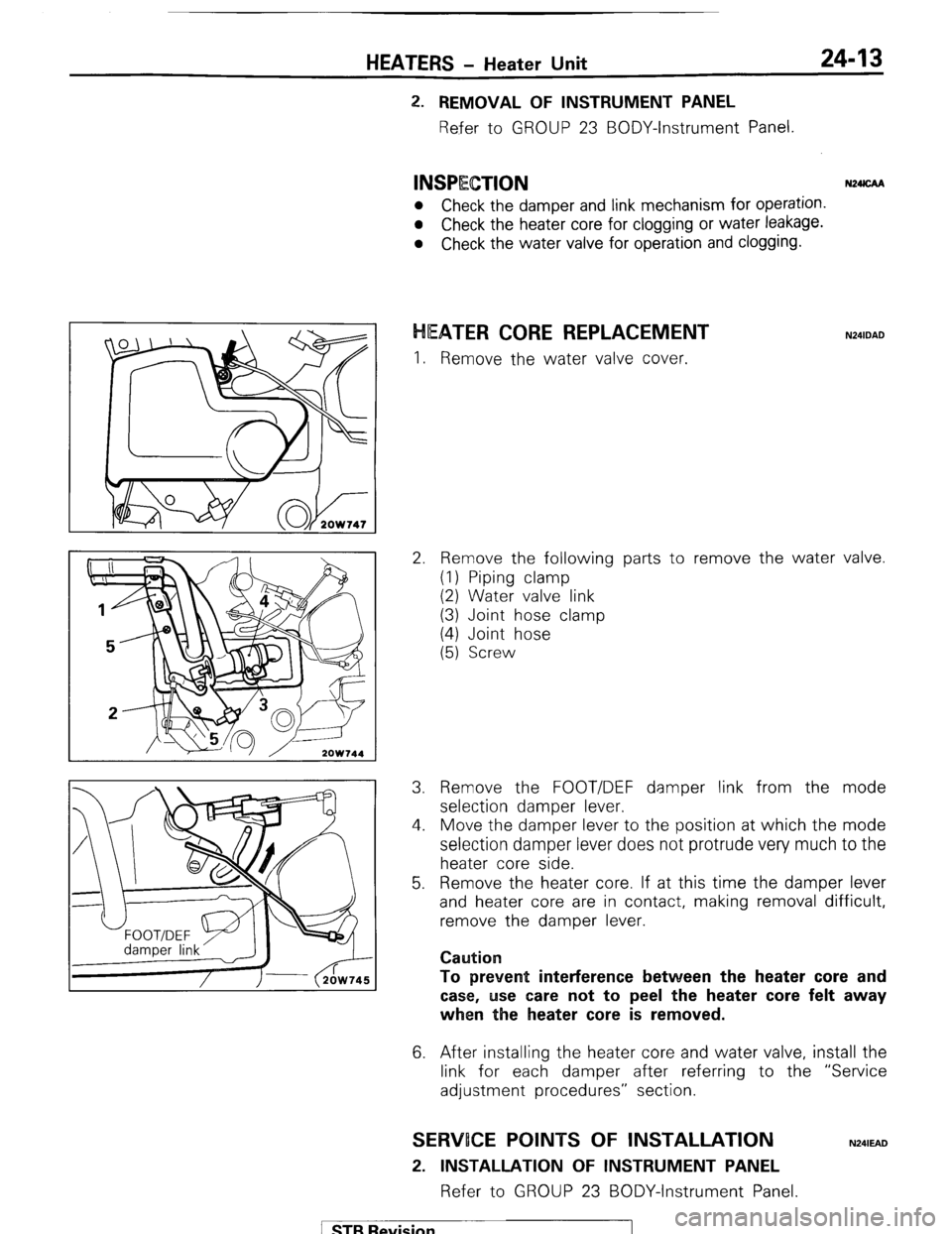
EATER CORE REPLACEMENT
I. Remove the water valve cover.
2. Remove the following parts to remove the water valve.
(1) Piping clamp
(2) Water valve link
(3) Joint hose clamp
(4) Joint hose
(5) Screw
3. Remove the FOOT/DEF damper link from the mode
selection damper lever.
4. Move the damper lever to the position at which the mode
selection damper lever does not protrude very much to the
heater core side.
5. Remove the heater core. If at this time the damper lever
and heater core are in contact, making removal difficult,
remove the damper lever.
Caution
To prevent interference between the heater
core and
case, use care not to peel the heater
core felt away
when the heater core is removed.
6. After installing the heater core and water valve, install the
link for each damper after referring to the “Service
adjustment procedures” section.
SERWOCE POINTS OF INSTALLATION
2. INSTALLATION OF INSTRUMENT PANEL
Refer to GROUP 23 BODY-Instrument Panel.
N241EAD
1 STB Revision
Page 250 of 284
24-14 HEATERS + Blower Assembly
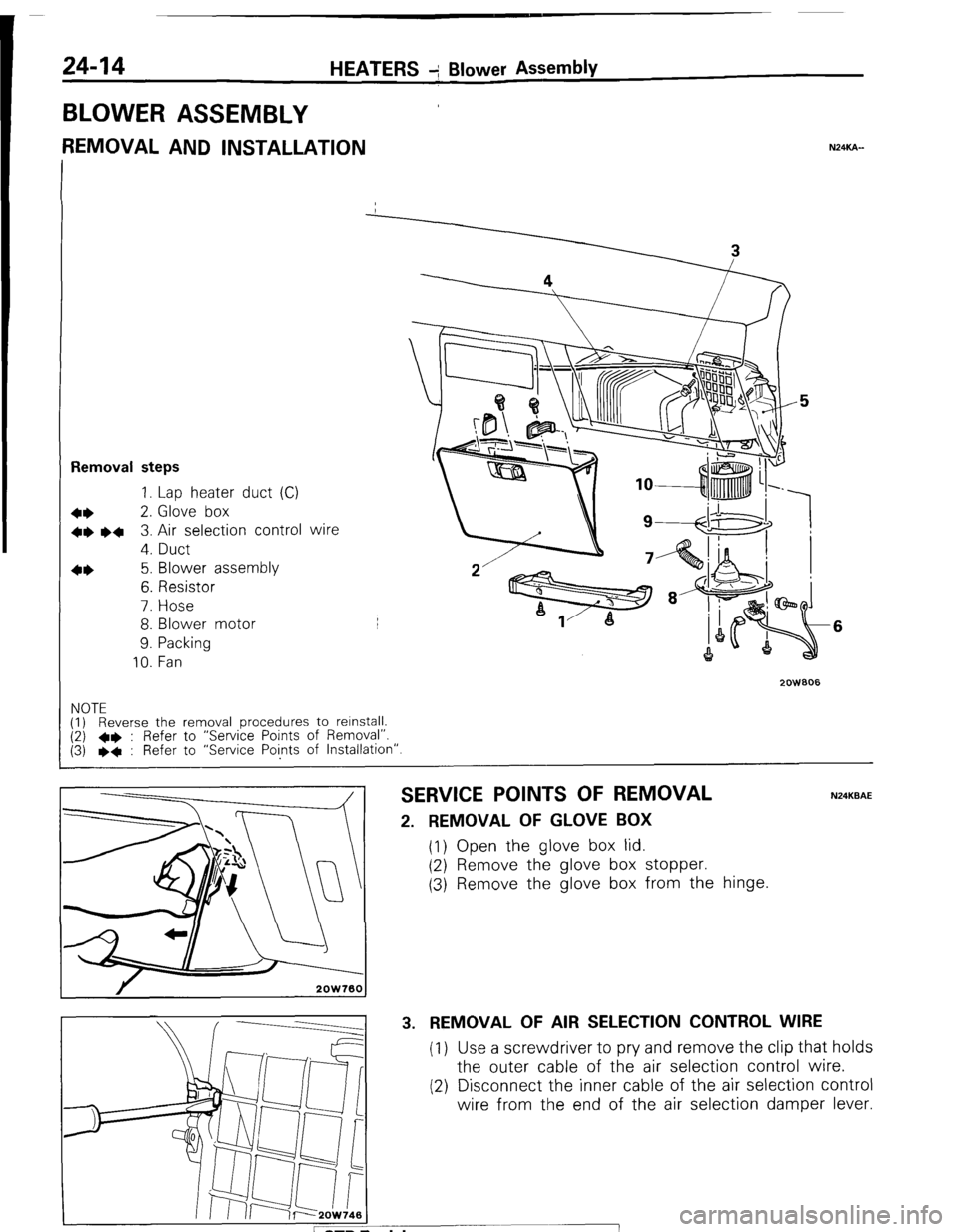
BLOWER ASSEMBLY
REMOVAL AND INSTALLATION NXKA-
Removal steps
1. Lap heater duct (C)
+* 2. Glove box
+e l + 3. Air selection control wire
4. Duct
4* 5. Blower assembly
6. Resistor
7. Hose
8. Blower motor
9. Packing
10. Fan
2oWBO6
6
NOTE
(1) Reverse the removal procedures to relnstall. (2) l * : Refer to “Service Points of Removal”.
(3) l * : Refer to “Service Points of Installation”.
SERVICE POINTS OF REMOVAL N24KBAE
2. REMOVAL OF GLOVE BOX
(1) Open the glove box lid.
(2) Remove the glove box stopper.
(3) Remove the glove box from the hinge.
3. REMOVAL OF AIR SELECTION CONTROL WIRE
(1) Use a screwdriver to pry and remove the clip that holds
the outer cable of the air selection control wire.
(2) Disconnect the inner cable of the air selection control
wire from the end of the air selection damper lever.
Page 251 of 284
HEATERS - Blower Assembly 24-15
--I
Front wirina harness
d
!
2OW537
2OW768
2OW779
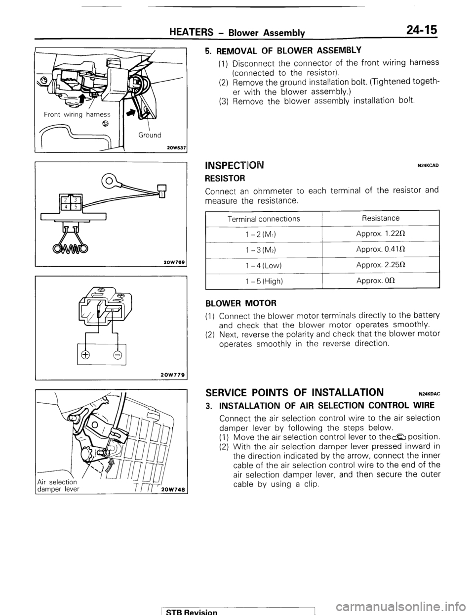
5. REMOVAL OF BLOWER ASSEMBLY (1) Disconnect the connector of the front wiring harness
(connected to the resistor).
(2) Remove the ground installation bolt. (Tightened togeth-
er with the blower assembly.)
(3) Remove the blower assembly installation bolt.
INSPECT00 N24KCAD
RESISTOR Connect an ohmmeter to each terminal of the resistor and
measure the resistance.
Terminal connections
1 -2(M1)
1 -3(M2) I-4(Low)
1 - 5 (High)
BLOWER MOTOR Resistance
Approx. 1.22R
Approx. 0.41 R
Approx. 2.25112
Approx. OlR
(1) Connect the blower motor terminals directly to the battery
and check that the blower motor operates smoothly.
(2) Next, reverse the polarity and check that the blower motor
operates smoothly in the reverse direction.
SERVICE POINTS OF INSTALLATION N24KDAC
3. INSTALLATION OF AIR SELECTION CONTROL WIRE Connect the air selection control wire to the air selection
damper lever by following the steps below.
(1) Move the air selection control lever to the& position.
(2) With the air selection damper lever pressed inward in
the direction indicated by the arrow, connect the inner
cable of the air selection control wire to the end of the
air selection damper lever, and then secure the outer
cable by using a clip.
1 STB Revision
Page 252 of 284
24-16 HEATER? - Ventilators
VENTILATORS
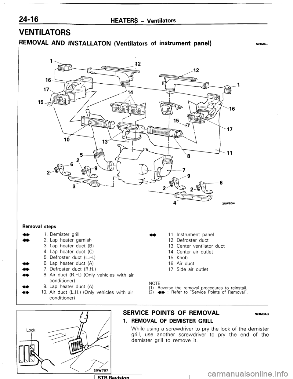
REMOVAL AND INSTALLATON (Ventilators of instrument panel) N24MA-
‘16
zowaa I4
Removal steps
1. Demister grill
2. Lap heater garnish
3. Lap heater duct (B)
4. Lap heater duct (C)
5. Defroster duct (L.H.)
6. Lap heater duct (A)
7. Defroster duct (R.H.)
8. Air duct (R.H.) (Only vehicles with air
conditioner)
9. Lap heater duct (A)
10. Air duct (L.H.) (Only vehicles with air
conditioner) 11. Instrument panel
12. Defroster duct
13. Center ventilator duct
14. Center air outlet
15. Knob
16. Air duct
17. Side air outlet
NOTE
(1) Reverse the removal procedures to reinstall.
(2) +e : Refer to “Service Points of Removal”
SERVICE POINTS OF REMOVAL N24MBAG
1. REMOVAL OF DEMISTER GRILL
While using a screwdriver to pry the lock of the demister
grill, use another screwdriver to pry the end of the
demister grill to remove it.
levision
Page 254 of 284
24-18 HEATERS - Ventilators
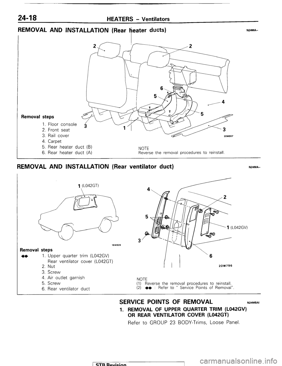
REMOVAL AND INSTALLATION [Rear heater ducts)
I 7F-T 'f------A
1
Removal steps 1. Floor console
2. Front seat
3. Rail cover
2ow.307 4. Carpet
5. Rear heater duct (B)
6. Rear heater duct (A)
NOTE
Reverse the removal procedures to reinstall.
REMOVAL AND INSTALLATION (Rear ventilator duct) N24MA-
1 (L042GT)
18W825
Removal steps
*I) 1. Upper quarter trim (L042GV)
Rear ventilator cover (L042GT)
2. Nut
3. Screw
4. Air outlet garnish
5. Screw
6. Rear ventilator duct
3
2OW796
NOTE
(1) Reverse the removal procedures to reinstall.
(2) +e : Refer to ” Service Points of Removal”.
SERVICE POINTS OF REMOVAL N24MBAI
1. REMOVAL OF UPPER QUARTER TRIM (L042GV)
OR REAR VENTILATOR COVER (L042GT) Refer to GROUP 23 BODY-Trims, Loose Panel.
( STB Revision
Page 256 of 284
24-20 AIR-CONDITION!NG-General Information
I
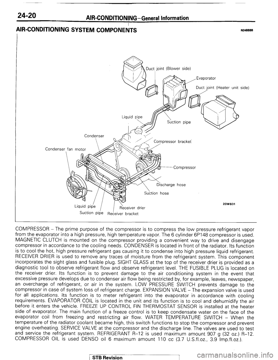
AIR-CONDITIONING SYSTEM COMPO
N24BBBB
Condenser MDuct, joint (Blower side)
oint (Heater unit
Condenser
2OWB31
Suction Pipe Receiver bracket side)
COMPRESSOR - The prime purpose of the compressor is to compress the low pressure refrigerant vapor
from the evaporator into a high pressure, high temperature vapor. The 6 cylinder 6P148 compressor is used.
MAGNETIC CLUTCH is mounted on the compressor providing a convenient way to drive and disengage
compressor in accordance to the cooling needs. CONDENSER is located in front of the radiator. Its function
is to cool the hot, high pressure refrigerant gas causing it to condense into high pressure liquid refrigerant.
RECEIVER DRIER is used to remove any traces of moisture from the refrigerant system. This component
incorporates the sight glass and fusible plug. SIGHT GLASS at the top of the receiver drier is provided as a
diagnostic tool to observe refrigerant flow and observe refrigerant level. THE FUSIBLE PLUG is located on
the receiver drier. Its function is to prevent damage to the air conditioning system in the event that
excessive pressure develops due to condenser air flow being restricted by, for example, leaves, newspaper,
an overcharge of refrigerant, or air in the system. LOW PRESSURE SWITCH prevents damage to the
compressor in case of system loss of refrigerant charge. EXPANSION VALVE - The expansion valve is used
for all applications. Its function is to meter refrigerant into the evaporator in accordance with cooling
requirements. EVAPORATOR COIL is located in the unit and its function is to cool and dehumidify the air
before it enters the vehicle. FREEZE UP CONTROL FIN THERMOSTAT SENSOR is installed at the heater
side of evaporator. The main function of a freeze control is to keep condensate water on the face of the
evaporator coil from freezing and restricting air flow. WATER TEMPERATURE SWITCH - When the
temperature of the radiator coolant became high, this switch functions to stop the compressor and prevent
engine overheating. SERVICE VALVE at the compressor and the discharge line. The valves are used to test
and service the refrigerant system. REFRIGERANT R-12 is used maximum amount 907 g (32 oz.) R-12.
COMPRESSOR OIL is used DENS0 oil 6 maximum amount 110 cc (3.7 U.S.fl.oz., 3.9 Imp.fl.oz.).
/ STB Revision
Page 257 of 284
AIR-CONDITIONING -Specifications
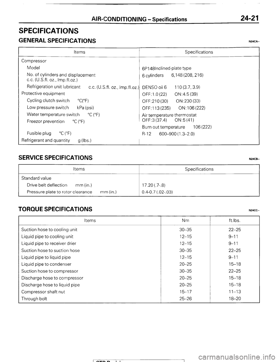
SPECIFICATIONS
GENERAL SPECIFICATIONS
24-2 1
N24CA-
Items Specifications
Compressor
Model
6P148lnclined-plate type
No. of cylinders and displacement
6 cylinders 6,148 (208,216)
cc. (U.S.fl. oz., Imp.fl.02.)
Refrigeration unit lubricant
cc. (U.S.fl. oz., Imp.fl.oz.) DENS0 oil 6 110 (3.7,3.9)
Protective equipment
OFF: 1 .O (22) ON:4.5 (39)
Cycling clutch switch
“C(“F)
OFF:210 (30) ON:230 (33)
Low pressure switch
kPa (psi)
OFF: 113 (235) ON:106(222)
Water temperature switch
“C (“F)
Air temperature thermostat
Freezor prevention
“C (“F) OFF:3 (37.4) ON:5 (41)
Burn out temperature 106 (222)
Fusible plug “C (“F)
R-l 2 600-900 (1.3-2.0)
Refrigerant and quantity
g (Ibs.1
SERVICE SPECIFICATIONS N24CE-
Items Specifications
Standard value
Drive belt deflection mm (in.) 17.20 (.7-.8)
Pressure plate to rotor clearance mm (in.)
0.4-0.7 (.02-.03)
TORQUE SPECIFICATIONS N24CG Items Nm ftlbs.
Suction hose to cooling unit 30-35 22-25
Liquid pipe to cooling unit 12-15 9-l 1
Liquid pipe to receiver drier 12-15 9-l 1
Suction hose to suction hose 30-35 22-25
Liquid pipe to liquid pipe 12-15 9-l 1
Liquid pipe to condenser 20-25 15-18
Suction hose to compressor 30-35 22-25
Discharge hose to compressor 20-25 15-18
Discharge hose to liquid pipe 20-25 15-18
Compressor shaft nut 15-17 11-13
Through bolt 25-26 18-20
/ STB Revision I
Page 260 of 284
AIR-CONDITIONING-Service Adjustment Procedures
SERVICE ADJUSTMENT PROCQDURES 24-29 N24FDAD
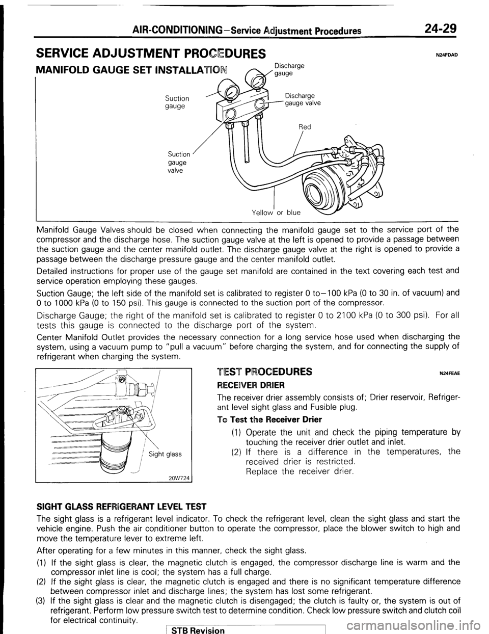
MANIFOLD GAUGE SET INSTALLATUON Discharge
W gauge
Suction
gauge
Suction
gauge
valve Manifold Gauge Valves should be closed
when connecting the manifold gauge set to the service port of the
compressor and the discharge hose. The suction gauge valve at the left is opened to provide a passage between
the suction gauge and the center manifold outlet. The discharge gauge valve at the right is opened to provide a
passage between the discharge pressure gauge and the center manifold outlet.
Detailed instructions for proper use of the gauge set manifold are contained in the text covering each test and
service operation employing these gauges.
Suction Gauge; the left side of the manifold set is calibrated to register 0 to-100 kPa (0 to 30 in. of vacuum) and
0 to 1000 kPa (0 to 150 psi). This gauge is connected to the suction port of the compressor.
Discharge Gauge; the right of the manifold set is calibrated to register 0 to 2100 kPa (0 to 300 psi). For all
tests this gauge is connected to the discharge port of the system.
Center Manifold Outlet provides the necessary connection for a long service hose used when discharging the
system, using a vacuum pump to “pull a vacuum” before charging the system, and for connecting the supply of
refrigerant when charging the system
glass -
2OW724 N24FEAE The receiver drier assembly consists of; Drier reservoir, Refriger-
ant level sight glass and Fusible plug.
To Test the Receiver Drier (1) Operate the unit and check the piping temperature by
touching the receiver drier outlet and inlet.
(2) If there is a difference in the temperatures, the
received drier is restricted.
Replace the receiver drier.
SIGHT GLASS REFRlGERANT LEVEL TEST The sight glass is a refrigerant level indicator. To check the refrigerant level, clean the sight glass and start the
vehicle engine. Push the air conditioner button to operate the compressor, place the blower switch to high and
move the temperature lever to extreme left.
After operating for a few minutes in this manner, check the sight glass.
(1) If the sight glass is clear, the magnetic clutch is engaged, the compressor discharge line is warm and the
compressor inlet line is cool; the system has a full charge.
(2) If the sight glass is clear, the magnetic clutch is engaged and there is no significant temperature difference
between compressor inlet and discharge lines; the system has lost some refrigerant.
(3) If the sight glass is clear and the magnetic clutch is disengaged; the clutch is faulty or, the system is out of
refrigerant. Perform low pressure switch test to determine condition. Check low pressure switch and clutch coil
for electrical continuity.
1 STB Revision
Page 264 of 284
24-28 AIR-CONDITIONING-Safety Precautions
SAFETY PRECAUTIONS N24PAAB
SAFETY PRECAUTIONS
I
The refrigerant used in all air-conditioning installations is R-12. It is transparent and colorless in both the liquid and
vapor state. Since it has a boiling point of -29.8T (-21.7”F). at atmospheric pressure, it will be a vapor at all normal
temperatures and pressures. The vapor is heavier than air, non- flammable, and nonexplosive. It is nonpoisonous
except when it is in direct contact with open flame. It is noncorrosive except when combined with water. The
following precautions must be observed when handling R-12.
Caution
Wear
safety goggles when servicing the refrigeration system.
R-12 evaporates so rapidly at normal atmospheric pressures and temperatures that it tends to freeze anything it
contacts. For this reason, extreme care must be taken to prevent any liquid refrigerant from contacting the skin and
especially the eyes.
Always wear safety goggles when servicing the refrigeration part of the air- conditioning system. Keep a bottle of
sterile mineral oil handy when working on the refrigeration system. Should any liquid refrigerant get into the eyes,
use a few drops of mineral oil to wash them out. RI12 is rapidly absorbed by the oil. Next, splash the eyes with
plenty of cold water. Call your doctor immediately even though irritation has ceased after treatment.
Caution
Do not heat R-12 above 52°C (125°F).
In most instances, moderate heat is required to bring the pressure of the refrigerant in its container above the
pressure of the system when charging or adding refrigerant. A bucket or large pan of hot water not over 52°C
(125°F) is all the heat required for this purpose. Do not heat the refrigerant container with a blow torch or any other
means that would raise temperature and pressure above this temperature. Do not weld or steam clean on or near
the system components or refrigerant lines.
Caution
Keep R-12 containers upright when charging the system.
When metering R-12 into the refrigeration system, keep the supply tank or cans in an upright position. If the
refrigerant container is on its side or upside down, liquid refrigerant will enter the system and damage the
compressor.
Caution
Always work in a well-ventilated room.
Good ventilation is vital in the working area. Always discharge the refrigerant into the service bay exhaust system
or outside the building. Large quantities of refrigerant vapor in a small, poorly ventilated room can displace the air
and cause suffocation.
Although R-12 vapor is normally nonpoisonous, contact with an open flame can cause the vapor to become very
poisonous. Do not discharge large quantities of refrigerant in an area having an open flame. A poisonous gas is
producted when using the flame-type leak detector. Avoid inhaling the fumes from the leak detector.
Caution
Do not allow liquid refrigerant to touch bright metal.
Refrigerant will tarnish bright metal and chrome surfaces, and in combination with moisture’can severely corrode
all metal surfaces.
/ STB Revision
-I