engine overheat MITSUBISHI MONTERO 1987 1.G Workshop Manual
[x] Cancel search | Manufacturer: MITSUBISHI, Model Year: 1987, Model line: MONTERO, Model: MITSUBISHI MONTERO 1987 1.GPages: 284, PDF Size: 14.74 MB
Page 97 of 284

CHARGING SYSTEM - Service Adjustment Procedures 8-77
SERVICE ADJUSTMENT PROCEDUREswmAB
lEL15I
INSPECTION OF THE CHARGING SYSTEM
VOLTAGE DROP TEST OF ALTERNATOR OUTPUT WIRE
This test judges whether or not the wiring (including the fusible
link) between the alternator B terminal and the battery (+) terminal
is sound by the voltage drop method.
Preparation
(1) Turn the ignition switch to “OFF”.
(2) Disconnect the battery ground cable.
(3) Disconnect the alternator output lead from the alternator “B”
terminal.
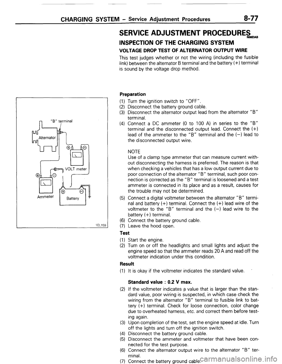
(4) Connect a DC ammeter (0 to 100 A) in series to the “B”
terminal and the disconnected output lead. Connect the (+)
lead of the ammeter to the “B” terminal and the (-) lead to
the disconnected output wire.
NOTE
Use of a clamp type ammeter that can measure current with-
out disconnecting the harness is preferred. The reason is that
when checking a vehicles that has a low output current due to
poor connection of the alternator “B” terminal, such poor con-
nection is corrected as the “B” terminal is loosened and a test
ammeter is connected in its place and as a result, causes for
the trouble may not be determined.
(5) Connect a digital voltmeter between the alternator “B” termi-
nal and battery (+) terminal. Connect the (+) lead wire of the
voltmeter to the “B” terminal and the (-) lead wire to the
battery (+) terminal.
(6) Connect the battery ground cable.
(7) Leave the hood open.
Test
(1) Start the engine.
(2) Turn on or off the headlights and small lights and adjust the
engine speed so that the ammeter reads 20 A and read off the
voltmeter indication under this condition.
Result
(1) It is okay if the voltmeter indicates the standard value. ’
Standard value : 0.2 V max.
(2) If the voltmeter indicates a value that is larger than the stan-
dard value, poor wiring is suspected, in which case check the
wiring from the alternator “B” terminal to fusible link to bat-
tery (+) terminal. Check for loose connection, color change
due to overheated harness, etc. and correct them before test-
ing again.
(3) Upon completion of the test, set the engine speed at idle. Turn
off the lights and turn off the ignition switch.
(4) Disconnect the battery ground cable.
(5) Disconnect the ammeter and voltmeter that have been con-
nected for the test purpose.
(6) Connect the alternator output wire to the alternator “B” ter-
minal.
(7) Connect the battery ground cable.
( STB Revision
Page 129 of 284

IGNITLON SYSTEM -Troubleshooting 8-109
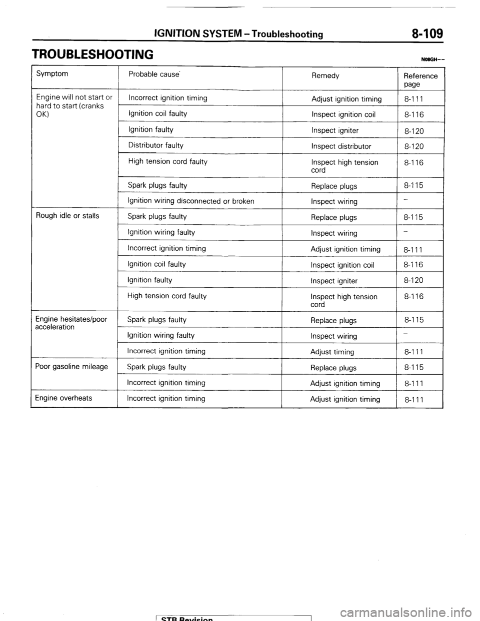
TROUBLESHOOTING
NOBGH--
Symptom Probable cause
Remedy
Reference
paw
Engine will not start or
Incorrect ignition timing
8-111
hard to start (cranks Adjust ignition timing
OKI Ignition coil faulty
Inspect ignition coil 8-116
Ignition faulty
Inspect igniter
8-120
Distributor faulty
Inspect distributor 8-120
High tension cord faulty
Inspect high tension 8-116
cord
Spark plugs faulty Replace plugs 8-115
Ignition wiring disconnected or broken
Inspect wiring -
Rough idle or stalls
Spark plugs faulty
Replace plugs 8-115
Ignition wiring faulty
Inspect wiring -
Incorrect ignition timing
Adjust ignition timing
8-111
Ignition coil faulty
Inspect ignition coil 8-116
Ignition faulty
Inspect igniter 8-120
High tension cord faulty
Inspect high tension 8-116
cord
Engine hesitates/poor
acceleration Spark plugs faulty Replace plugs 8-115
Ignition wiring faulty
Inspect wiring -
Incorrect ignition timing
Adjust timing 8-111
Poor gasoline mileage
Spark plugs faulty Replace plugs 8-115
Incorrect ignition timing Adjust ignition timing 8-111
Engine overheats Incorrect ignition timing
Adjust ignition timing
8-111 1 STB Revision
Page 256 of 284

24-20 AIR-CONDITION!NG-General Information
I
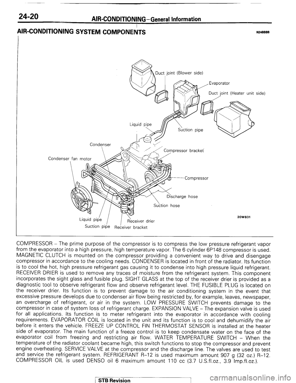
AIR-CONDITIONING SYSTEM COMPO
N24BBBB
Condenser MDuct, joint (Blower side)
oint (Heater unit
Condenser
2OWB31
Suction Pipe Receiver bracket side)
COMPRESSOR - The prime purpose of the compressor is to compress the low pressure refrigerant vapor
from the evaporator into a high pressure, high temperature vapor. The 6 cylinder 6P148 compressor is used.
MAGNETIC CLUTCH is mounted on the compressor providing a convenient way to drive and disengage
compressor in accordance to the cooling needs. CONDENSER is located in front of the radiator. Its function
is to cool the hot, high pressure refrigerant gas causing it to condense into high pressure liquid refrigerant.
RECEIVER DRIER is used to remove any traces of moisture from the refrigerant system. This component
incorporates the sight glass and fusible plug. SIGHT GLASS at the top of the receiver drier is provided as a
diagnostic tool to observe refrigerant flow and observe refrigerant level. THE FUSIBLE PLUG is located on
the receiver drier. Its function is to prevent damage to the air conditioning system in the event that
excessive pressure develops due to condenser air flow being restricted by, for example, leaves, newspaper,
an overcharge of refrigerant, or air in the system. LOW PRESSURE SWITCH prevents damage to the
compressor in case of system loss of refrigerant charge. EXPANSION VALVE - The expansion valve is used
for all applications. Its function is to meter refrigerant into the evaporator in accordance with cooling
requirements. EVAPORATOR COIL is located in the unit and its function is to cool and dehumidify the air
before it enters the vehicle. FREEZE UP CONTROL FIN THERMOSTAT SENSOR is installed at the heater
side of evaporator. The main function of a freeze control is to keep condensate water on the face of the
evaporator coil from freezing and restricting air flow. WATER TEMPERATURE SWITCH - When the
temperature of the radiator coolant became high, this switch functions to stop the compressor and prevent
engine overheating. SERVICE VALVE at the compressor and the discharge line. The valves are used to test
and service the refrigerant system. REFRIGERANT R-12 is used maximum amount 907 g (32 oz.) R-12.
COMPRESSOR OIL is used DENS0 oil 6 maximum amount 110 cc (3.7 U.S.fl.oz., 3.9 Imp.fl.oz.).
/ STB Revision
Page 267 of 284

AIR-CONDITIONING-Service Adiustment Procedures 24-31
FREEZE UP CONTROL
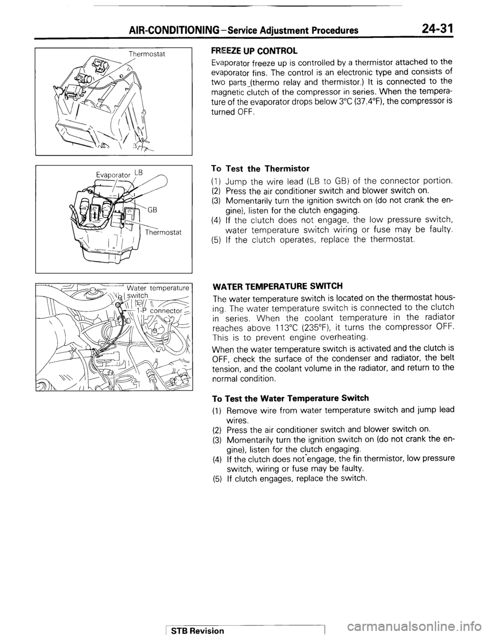
Evaporator freeze up is controlled by a thermistor attached to the
evaporator fins. The control is an electronic type and consists of
two parts_(thermo relay and thermistor.) It is connected to the
magnetic clutch of the compressor in series. When the tempera-
ture of the evaporator drops below 3°C (37.4”F), the compressor is
turned OFF.
To Test the Thermistor
(1) Jump the wire lead (LB to GB) of the connector portion.
(2) Press the air conditioner switch and blower switch on.
(3) Momentarily turn the ignition switch on (do not crank the en-
gine), listen for the clutch engaging.
(4) If the clutch does not engage, the low pressure switch,
water temperature switch wiring or fuse may be faulty.
(5) If the clutch operates, replace the thermostat.
WATER TEMPERATURE SWITCH
The water temperature switch is located on the thermostat hous-
ing. The water temperature switch is connected to the clutch
in series. When the coolant temperature in the radiator
reaches above 113°C (235”F), it turns the compressor OFF.
This is to prevent engine overheating.
When the water temperature switch is activated and the clutch is
OFF, check the surface of the condenser and radiator, the belt
tension, and the coolant volume in the radiator, and return to the
normal condition.
To Test the Water Temperature Switch
(1) Remove wire from water temperature switch and jump lead
wires.
(2) Press the air conditioner switch and blower switch on.
(3) Momentarily turn the ignition switch on (do not crank the en-
gine), listen for the clutch engaging.
(4) If the clutch does not-engage, the fin thermistor, low pressure
switch, wiring or fuse may be faulty.
(5) If clutch engages, replace the switch.
1 STB Revision