heating MITSUBISHI MONTERO 1987 1.G Workshop Manual
[x] Cancel search | Manufacturer: MITSUBISHI, Model Year: 1987, Model line: MONTERO, Model: MITSUBISHI MONTERO 1987 1.GPages: 284, PDF Size: 14.74 MB
Page 238 of 284

24-2 HEATERS - General Information
GENERAL INFORMATION 24BAAD
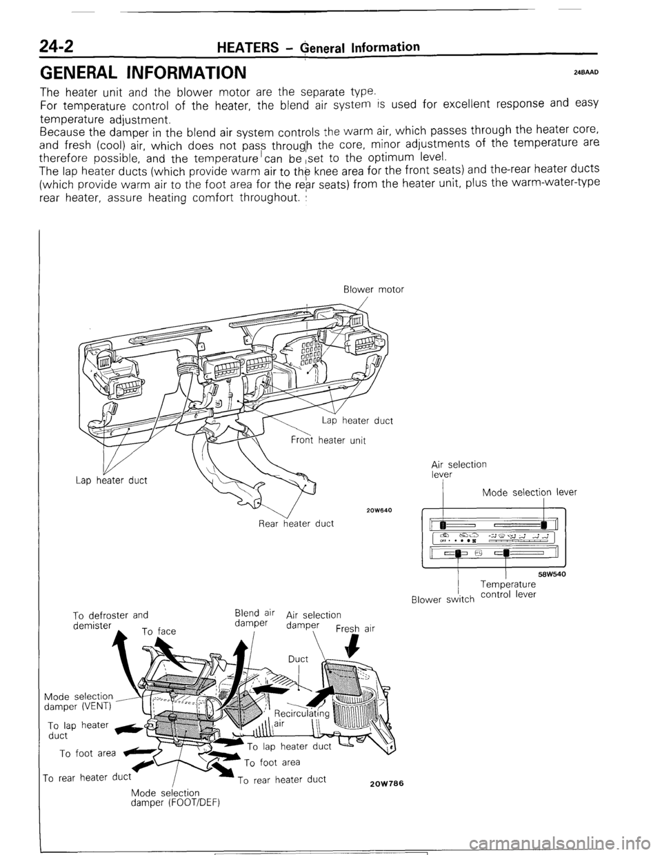
The heater unit and the blower motor are the separate type.
For temperature control of the heater, the blend air system is used for excellent response and easy
temperature adjustment.
Because the damper in the blend air system controls the warm air, which passes through the heater core,
and fresh (cool) air, which does not pass througlh the core, minor adjustments of the temperature are
therefore possible, and the temperature’can be ,set to the optimum level.
The lap heater ducts (which provide warm air to th$ knee area for the front seats) and the-rear heater ducts
(which provide warm air to the foot area for the rebr seats) from the heater unit, plus the warm-water-type
rear heater, assure heating comfort throughout. :
Blower motor
/
2OW640
Rear heater duct ;;eselection
I Mode selection lever
I I
58W540 Temperature
Blower switch contra’ lever To defroster and
Blend air Air selection
demister damper damper
Fresh air
Mode selection
damper (VENT) To lap heater &@
duct To foot area
ro rear heater duct To rear heater duct 2OW706 Mode selection damper (FOOT/DEF)
1 ST6 Revision
Page 256 of 284

24-20 AIR-CONDITION!NG-General Information
I
AIR-CONDITIONING SYSTEM COMPO
N24BBBB
Condenser MDuct, joint (Blower side)
oint (Heater unit
Condenser
2OWB31
Suction Pipe Receiver bracket side)
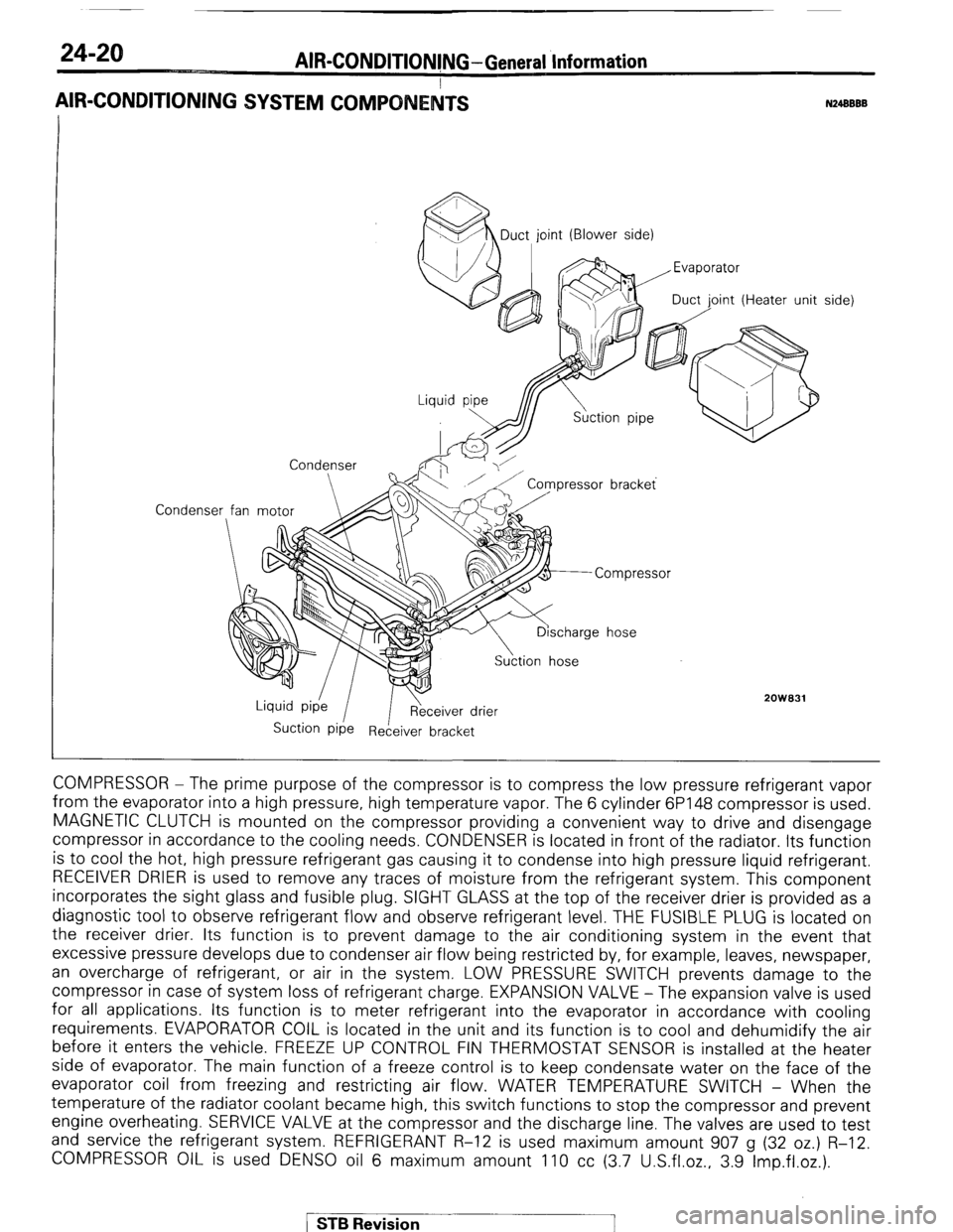
COMPRESSOR - The prime purpose of the compressor is to compress the low pressure refrigerant vapor
from the evaporator into a high pressure, high temperature vapor. The 6 cylinder 6P148 compressor is used.
MAGNETIC CLUTCH is mounted on the compressor providing a convenient way to drive and disengage
compressor in accordance to the cooling needs. CONDENSER is located in front of the radiator. Its function
is to cool the hot, high pressure refrigerant gas causing it to condense into high pressure liquid refrigerant.
RECEIVER DRIER is used to remove any traces of moisture from the refrigerant system. This component
incorporates the sight glass and fusible plug. SIGHT GLASS at the top of the receiver drier is provided as a
diagnostic tool to observe refrigerant flow and observe refrigerant level. THE FUSIBLE PLUG is located on
the receiver drier. Its function is to prevent damage to the air conditioning system in the event that
excessive pressure develops due to condenser air flow being restricted by, for example, leaves, newspaper,
an overcharge of refrigerant, or air in the system. LOW PRESSURE SWITCH prevents damage to the
compressor in case of system loss of refrigerant charge. EXPANSION VALVE - The expansion valve is used
for all applications. Its function is to meter refrigerant into the evaporator in accordance with cooling
requirements. EVAPORATOR COIL is located in the unit and its function is to cool and dehumidify the air
before it enters the vehicle. FREEZE UP CONTROL FIN THERMOSTAT SENSOR is installed at the heater
side of evaporator. The main function of a freeze control is to keep condensate water on the face of the
evaporator coil from freezing and restricting air flow. WATER TEMPERATURE SWITCH - When the
temperature of the radiator coolant became high, this switch functions to stop the compressor and prevent
engine overheating. SERVICE VALVE at the compressor and the discharge line. The valves are used to test
and service the refrigerant system. REFRIGERANT R-12 is used maximum amount 907 g (32 oz.) R-12.
COMPRESSOR OIL is used DENS0 oil 6 maximum amount 110 cc (3.7 U.S.fl.oz., 3.9 Imp.fl.oz.).
/ STB Revision
Page 267 of 284

AIR-CONDITIONING-Service Adiustment Procedures 24-31
FREEZE UP CONTROL
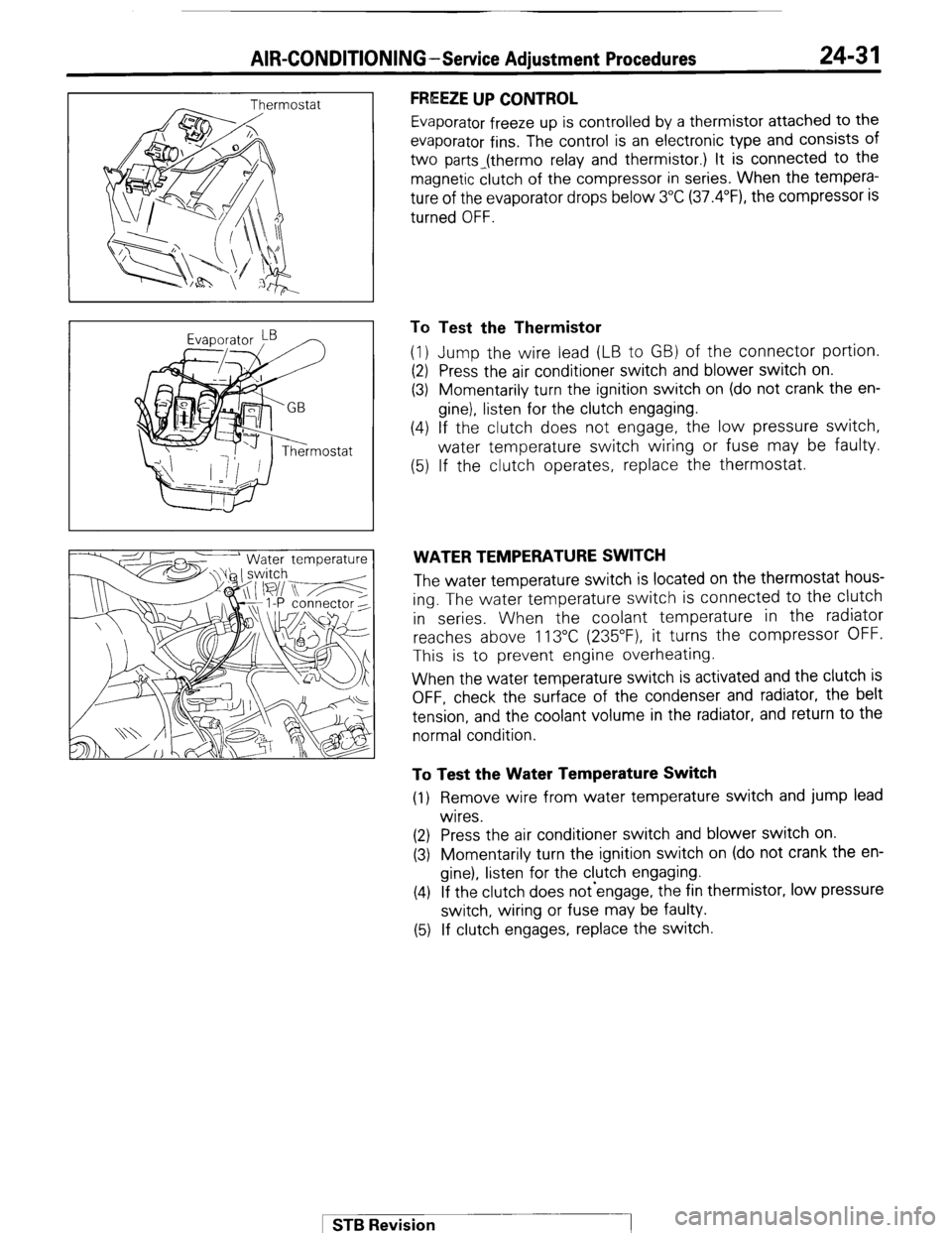
Evaporator freeze up is controlled by a thermistor attached to the
evaporator fins. The control is an electronic type and consists of
two parts_(thermo relay and thermistor.) It is connected to the
magnetic clutch of the compressor in series. When the tempera-
ture of the evaporator drops below 3°C (37.4”F), the compressor is
turned OFF.
To Test the Thermistor
(1) Jump the wire lead (LB to GB) of the connector portion.
(2) Press the air conditioner switch and blower switch on.
(3) Momentarily turn the ignition switch on (do not crank the en-
gine), listen for the clutch engaging.
(4) If the clutch does not engage, the low pressure switch,
water temperature switch wiring or fuse may be faulty.
(5) If the clutch operates, replace the thermostat.
WATER TEMPERATURE SWITCH
The water temperature switch is located on the thermostat hous-
ing. The water temperature switch is connected to the clutch
in series. When the coolant temperature in the radiator
reaches above 113°C (235”F), it turns the compressor OFF.
This is to prevent engine overheating.
When the water temperature switch is activated and the clutch is
OFF, check the surface of the condenser and radiator, the belt
tension, and the coolant volume in the radiator, and return to the
normal condition.
To Test the Water Temperature Switch
(1) Remove wire from water temperature switch and jump lead
wires.
(2) Press the air conditioner switch and blower switch on.
(3) Momentarily turn the ignition switch on (do not crank the en-
gine), listen for the clutch engaging.
(4) If the clutch does not-engage, the fin thermistor, low pressure
switch, wiring or fuse may be faulty.
(5) If clutch engages, replace the switch.
1 STB Revision