tow MITSUBISHI MONTERO 1987 1.G Workshop Manual
[x] Cancel search | Manufacturer: MITSUBISHI, Model Year: 1987, Model line: MONTERO, Model: MITSUBISHI MONTERO 1987 1.GPages: 284, PDF Size: 14.74 MB
Page 14 of 284
INTRODUCTION - Towing and Hoisting
TOWING AND HOISTING NOOGA-
This vehicle can only be towed from the front with convention-
al sling-type equipment and tow chain with grab hooks.
If a vehicle is towed from the rear, use a tow dolly.
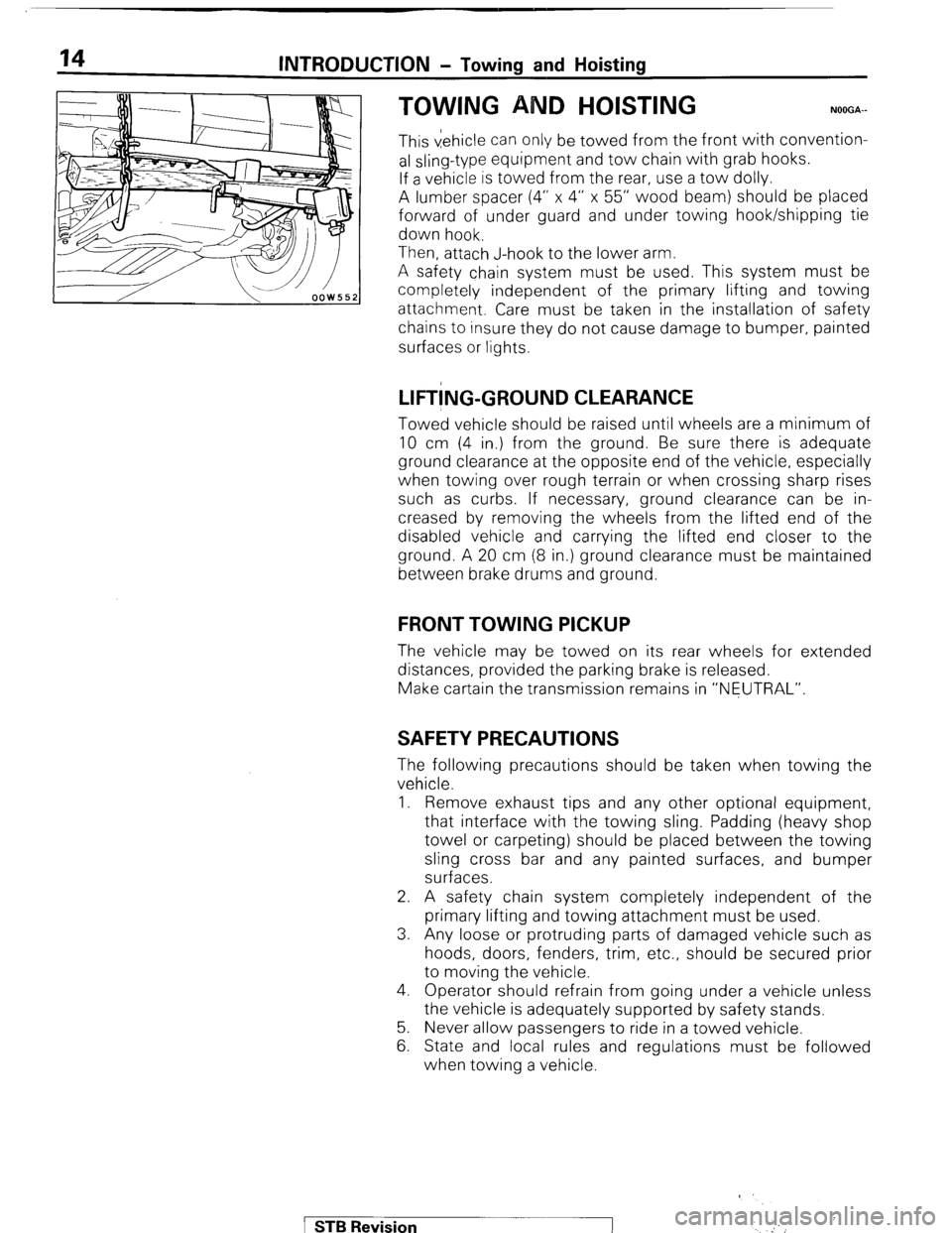
A lumber spacer (4” x 4” x 55” wood beam) should be placed
forward of under guard and under towing hook/shipping tie
down hook.
Then, attach J-hook to the lower arm.
A safety chain system must be used. This system must be
completely independent of the primary lifting and towing
attachment. Care must be taken in the installation of safety
chains to insure they do not cause damage to bumper, painted
surfaces or lights.
LIFT!NG-GROUND CLEARANCE
Towed vehicle should be raised until wheels are a minimum of
10 cm (4 in.) from the ground. Be sure there is adequate
ground clearance at the opposite end of the vehicle, especially
when towing over rough terrain or when crossing sharp rises
such as curbs. If necessary, ground clearance can be in-
creased by removing the wheels from the lifted end of the
disabled vehicle and carrying the lifted end closer to the
ground. A 20 cm (8 in.) ground clearance must be maintained
between brake drums and ground.
FRONT TOWING PICKUP
The vehicle may be towed on its rear wheels for extended
distances, provided the parking brake is released.
Make cartain the transmission remains in “NEUTRAL”.
SAFETY PRECAUTIONS
The following precautions should be taken when towing the
vehicle.
1. Remove exhaust tips and any other optional equipment,
that interface with the towing sling. Padding (heavy shop
towel or carpeting) should be placed between the towing
sling cross bar and any painted surfaces, and bumper
surfaces.
2. A safety chain system completely independent of the
primary lifting and towing attachment must be used.
3. Any loose or protruding parts of damaged vehicle such as
hoods, doors, fenders, trim, etc., should be secured prior
to moving the vehicle.
4. Operator should refrain from going under a vehicle unless
the vehicle is adequately supported by safety stands.
5. Never allow passengers to ride in a towed vehicle.
6. State and local rules and regulations must be followed
when towing a vehicle.
1 STB Revision
‘
Page 15 of 284
INTRODUCTION - Towing and Hoisting
HOISTING
POST TYPE
15
Special care should be taken when raising the vehicle on a
frame contact type hoist. The hoist must be equipped with the
proper adapters in order to support the vehicle at the proper
locations. (See next page)
Conventional hydraulic hoists may be used after determining
that the adapter plates will make firm contact with the side
frame.
FLOOR JACK
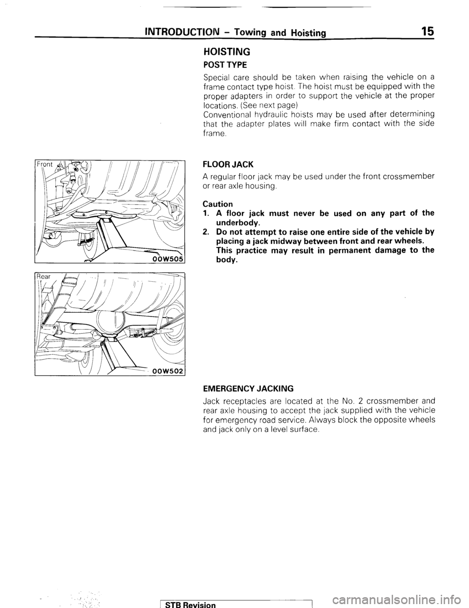
A regular floor jack may be used under the front crossmember
or rear axle housing.
Caution
1. A floor jack must never be used on any part of the
underbody.
2. Do not attempt to raise one entire side of the vehicle by
placing a jack midway between front and rear wheels.
This practice may result in permanent damage to the
body.
EMERGENCY JACKING
Jack receptacles are located at the No. 2 crossmember and
rear axle housing to accept the jack supplied with the vehicle
for emergency road service. Always block the opposite wheels
and jack only on a level surface.
.::
. Y!’ ,,. I
.I
‘.
1 STB Revision
Page 16 of 284
16 INTRODUCTION - Towitng and Hoisting
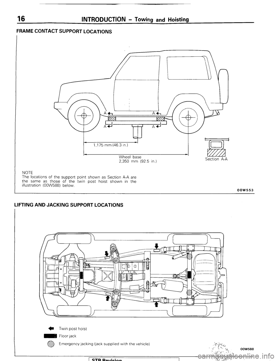
FRAME CONTACT SUPPORT LOCATIONS
2,350 mm (92.5 in.) Section A-A
NOTE
The locations of the support point shown as Section A-A are
the same as those of the twin post hoist shown in the
illustration (OOW588) below.
oow553
LIFTING AND JACKING SUPPORT LOCATIONS
c Twin post hoist
m Floor lack
@B Emergency jacking (jack supplied with the vehicle)
OOW588
Page 121 of 284
STARTING SYSTEM-Starter Motor 8-101
Snap
L Armature
1ELlO
pi-
SERVICE POINTS OF DISASSEMBLY
9. CAUTION OF ARMATURE/ll. BALL
When removing the armature, do not lose the ball which acts
as a bearing for the armature and tip.
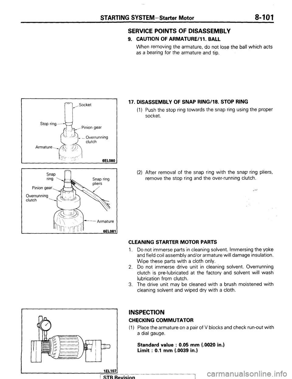
17. DISASSEMBLY OF SNAP RING/18. STOP RING
(1) Push the stop ring towards the snap ring using the proper
socket.
(2) After removal of the snap ring with the snap ring pliers,
remove the stop ring and the over-running clutch.
CLEANING STARTER MOTOR PARTS
1, Do not immerse parts in cleaning solvent. Immersing the yoke
and field coil assembly and/or armature will damage insulation.
Wipe these parts with a cloth only.
2. Do not immerse drive unit in cleaning solvent. Overrunning
clutch is pre-lubricated at the factory and solvent will wash
lubrication from clutch.
3. The drive unit may be cleaned with a brush moistened with
cleaning solvent and wiped dry with a cloth.
INSPECTION
CHECKING COMMUTATOR
(1) Place the armature on a pair of V blocks and check run-out with
a dial gauge.
Standard value : 0.05 mm (-0020 in.)
Limit : 0.1 mm (.0039 in.)
wision
I
Page 126 of 284
IGNITION SYSTEM-General Information
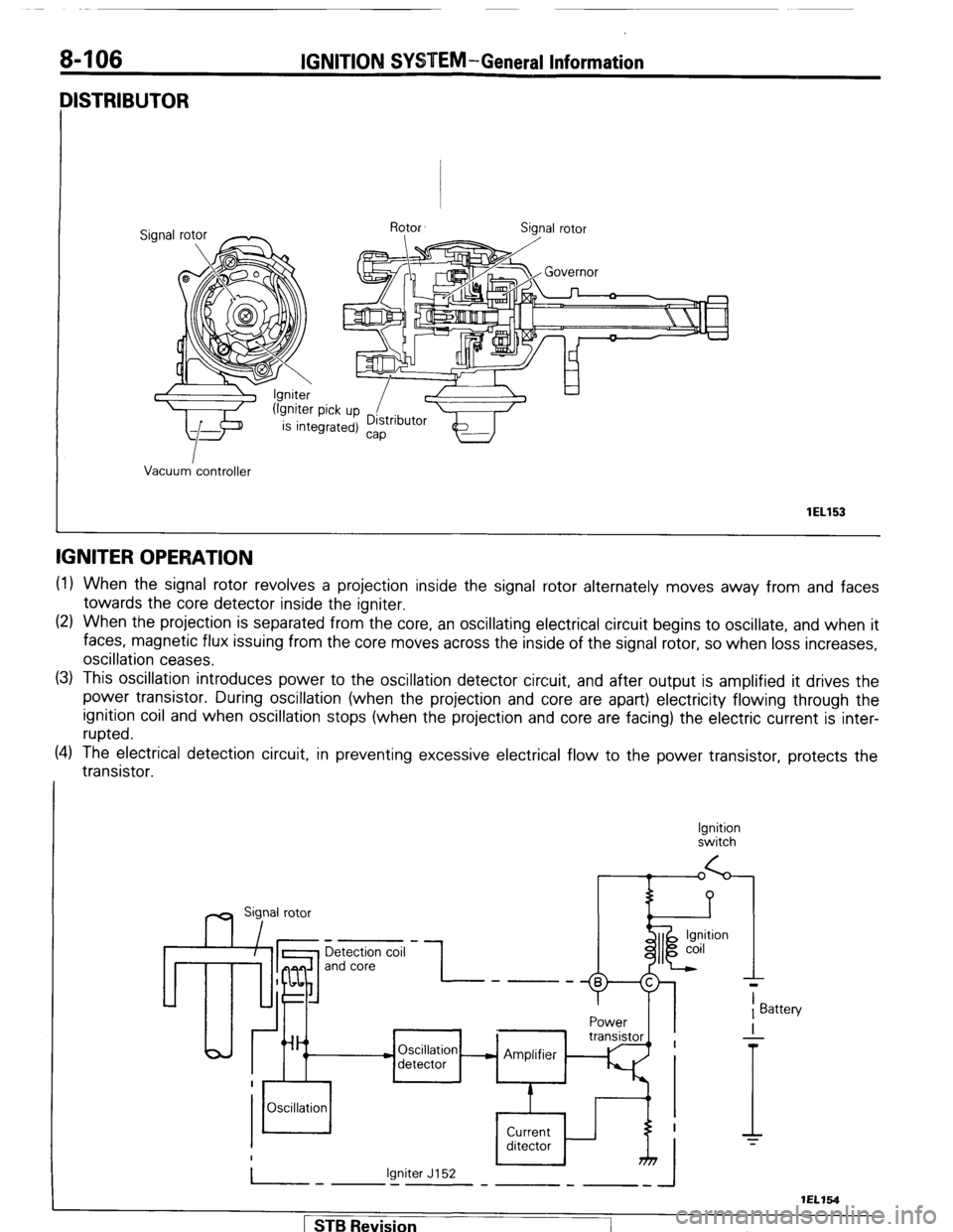
IISTRIBUTOR
Vacuum controller
lEL153
IGNITER OPERATION
(1) When the signal rotor revolves a projection inside the signal rotor alternately moves away from and faces
towards the core detector inside the igniter.
(2) When the projection is separated from the core, an oscillating electrical circuit begins to oscillate, and when it
faces, magnetic flux issuing from the core moves across the inside of the signal rotor, so when loss increases,
oscillation ceases.
(3) This oscillation introduces power to the oscillation detector circuit, and after output is amplified it drives the
power transistor. During oscillation (when the projection and core are apart) electricity flowing through the
ignition coil and when oscillation stops (when the projection and core are facing) the electric current is inter-
rupted.
(4) The electrical detection circuit, in preventing excessive electrical flow to the power transistor, protects the
transistor.
Ignition
switch
m Sig,nal rotor
Detection coil
and core -I- ----
Power
Oscillation - Amplifier
detector
Oscillation
Current
ditector
Igniter J152
-.I-
T
1 Battery
I
-
T
1 STB Revision
-7
Page 133 of 284
IGNITION SYSTEM-Service Adjustment Procedures 8-113
SPARK TEST - ENGINE CANNOT BE CRANKED
If spark test is performed by cranking while the catalyst is hot,
unburned gas will be supplied to the catalyst, and this is not de-
sirable to the catalyst.
For this reason, use the following methods which allow spark test
to be performed without cranking.
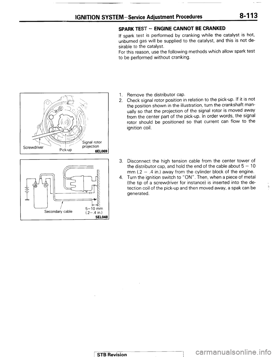
1. Remove the distributor cap.
2. Check signal rotor position in relation to the pick-up. If it is not
the position shown in the illustration, turn the crankshaft man-
ually so that the projection of the signal rotor is moved away
from the center part of the pick-up. In order words, the signal
rotor should be positioned so that current can flow to the
ignition coil.
3. Disconnect the high tension cable from the center tower of
the distributor cap, and hold the end of the cable about 5 - 10
mm (.2 - .4 in.) away from the cylinder block of the engine.
4. Turn the ignition switch to “ON”. Then, when a piece of metal
(the tip of a screwdriver for instance) is inserted into the de-
tection coil of the pick-up and then moved away, a spak can be
generated.
+
!:’
Secondary cable 5-10 km
(.2-.4 in.)
5EL0
1 STB Revision
Page 227 of 284
BACK DOOR WINDOW DEFOGGER - Printed Heater Lines B-207
Normal characteristic curve
Voltage
I;\
Positive
terminal Printed heater line Negative
terminal
Abnormal characteristic curve
Voltage
IZV
6V
ov :-
Tf I Open-circuit
I point
I
i
!
Positive Printed heater line Negative
terminal terminal
161332
Alignme.nt holes
Masking tape
16FfiSCl
PRINTED HEATER LINES
INSPECTION N08PKAA
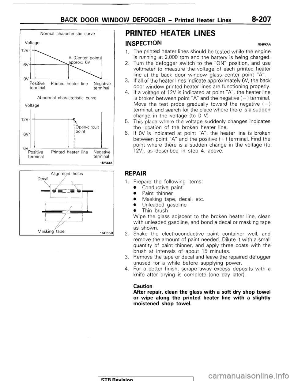
1. The printed heater lines should be tested while the engine
is running at 2,000 rpm and the battery is being charged.
2. Turn the defogger switch to the “ON” position, and use
voltmeter to measure the voltage of each printed heater
line at the back door window glass center point “A”.
3. If all of the heater lines indicate approximately 6V, the back
door window printed heater lines are functioning properly.
4. If a voltage of 12V is indicated at point “A”, the heater line
is broken between point “A” and the negative (-) terminal.
Move the test probe gradually toward the negative (-)
terminal, and search for the place where there is a sudden
change in the voltage (to 0 V).
5. This place where the voltage suddenly changes indicates
the location of the broken heater line.
6. If OV is indicated at point “A”, the heater line is broken
between point “A” and the positive (+) terminal. Find the
point where there is a sudden change in the voltage (to
12V). as described in step 4. above.
REPAIR
I. Prepare the following items:
e Conductive paint
@ Paint thinner
e Masking tape, decal, etc.
a, Unleaded gasoline
@ Thin brush
Wipe the glass adjacent to the broken heater line, clean
with unleaded gasoline, and bond a decal or masking tape
as shown.
2. Shake the electroconductive paint container well, and
remove the amount of paint needed. Dilute it with a small
quantity of paint thinner, and apply three coats with the
brush at intervals of about 15 minutes.
3. Remove the tape or decal and leave the repaired defogger
unused for a while before supplying power.
4. For a better finish, scrape away excess deposits with a
knife after drying is complete (one day later).
Caution
After repair, clean the glass with a soft dry shop towel
or wipe along the printed heater line with a slightly
moistened shop towel.
1 STB Revision
Page 280 of 284
24-44 AIR-CONDOTIONING-Evaporator
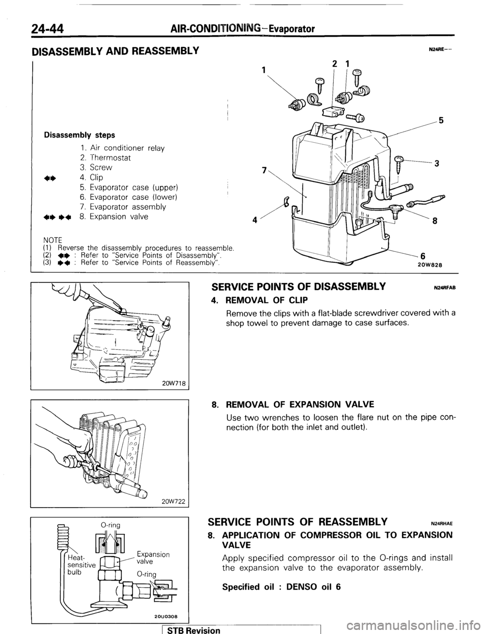
DISASSEMBLY AND REASSEMBLY
1
Disassembly steps
1. Air conditioner relay
2. Thermostat
3. Screw
4* 4. Clip
5. Evaporator case (upper)
6. Evaporator case (lower)
7. Evaporator assembly
+e l + 8. Expansion valve
NOTE
(1) Reverse the disassembly procedures to reassemble.
(2) +e : Refer to “Service Points of Disassembly”.
(3) l + : Refer to “Service Points of Reassembly”.
N24RE-- -6
2OW828
2OW718
2ow722
a 0-rina
Expansion
valve
O-rim
SERVICE POINTS OF DISASSEMBLY
4. REMOVAL OF CLIP
N24RFAB Remove the clips with a flat-blade screwdriver covered with a
shop towel to prevent damage to case surfaces.
8. REMOVAL OF EXPANSION VALVE Use two wrenches to loosen the flare nut on the pipe con-
nection (for both the inlet and outlet).
SERVICE POINTS OF REASSEMBLY N24RHAE
8. APPLICATION OF COMPRESSOR OIL TO EXPANSION
VALVE Apply specified compressor oil to the O-rings and install
the expansion valve to the evaporator assembly.
Specified oil : DENS0 oil 6
1 STB Revision