engine MITSUBISHI MONTERO 1987 1.G Workshop Manual
[x] Cancel search | Manufacturer: MITSUBISHI, Model Year: 1987, Model line: MONTERO, Model: MITSUBISHI MONTERO 1987 1.GPages: 284, PDF Size: 14.74 MB
Page 1 of 284
Service Manual
MONTERO
1987 : Volume 2
FOREWORD
This Service Manual has been prepared with the
latest service information available at the time of
publication. It is subdivided into various group
categories and each section contains diagnosis,
disassembly, repair, and installation procedures
along with complete specifications and tightening
references. Use of this manual will aid in properly
performing any servicing necessary to maintain or
restore the high levels of performance and reliability
designed into these outstanding vehicles.
WE SUPPORT
VOLUNTARY TECHNICIAN
CERTIFICATION THROUGH
MITSUBISHI MOTOR SALES OF AMERICA. Inc.
Mitsubishi Motors corporation reserves the right to make changes in
design or to make additions to or improvements in its products without
imposing any obligations upon itself to install them on its products
previously manufactured.
I
GROUP/SECTION INDEX ‘kme-.
INTRODUCTION ..............................
Electrical ...........................................
Electrical System Parts
Location .........................................
Relays, Control Units, Sensors,
Fuses, Groundings
Inspection of Harness
Connector ......................................
Wiring Harness .............................
Charging System ..........................
Starting System ............................
Ignition System .............................
Meters and Gauges ......................
Lighting System .............................
Wiper and Washer System ..........
Horn ...............................................
Accessory ......................................
Audio System ................................
Back Door Window Defogger ......
Automatic Free-wheeling Hub
Indicator System ..........................
Heaters and Air-conditioning .........
Heaters ..........................................
Air-conditioning ............................
**, For Engine Chassis & Body refer to
0 1986 Mitsubishi Motors Corporation Printed in Japan
Page 2 of 284
2 INTRODUCTION - How To Use This Manual
HOW TO USE THIS MANUAL NOOBAAK
CONTENTS
The preceding page contains the GROUP INDEX
which lists the group title and group number.
PAGE NUMBERS
All page numbers consist of two sets of digits
separated by a dash. The digits preceding the dash
identify the number of the group. The digits follow-
ing the dash represent the consecutive page
number within the group. The page numbers can
be found on the top left or right of each page.
TEXT
Unless otherwise specified, each service procedure
covers all models. Procedures covering specific
models are identified by the model codes, or similar
designation (engine type, transmission type, etc.).
A description of these designations is covered in
this unit under “VEHICLE IDENTIFICATION”.
SERVICE PROCEDURES
The service steps are arranged in numerical order
and attentions to be paid in performing vehicle ser-
vice are described in detail in SERVICE POINTS.
DEFINITION OF TERMS
STANDARD VALUE
Indicates the value used as the standard for judging
the quality of a part or assembly on inspection or the
value to which the part or assembly is corrected and
adjusted. It is given by tolerance.
LIMIT
Shows the standard for judging the quality of a part
or assembly on inspection and means the maximum
or minimum value within which the part or assembly
must be kept functionally or in strength. It is a value
established outside the range of standard value. Installation steps
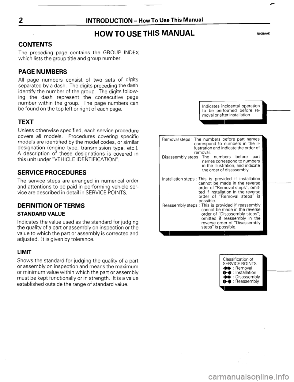
Indicates incidental operation
piiiKL=l-
Removal steps : The numbers before part names
correspond to numbers in the il-
lustration and indicate the order of
removal.
Disassembly steps : The numbers before part
names correspond to numbers
in the illustration, and indicate
the order of disassembly.
This is provided if installation
cannot be made in the reverse
order of “Removal steps”; omit-
ted if installation in the reverse
order of “Removal steps” is
possible.
.
Reassembly steps : I his IS provided It reassembly
cannot be made in the reverse
order of “Disassembly steps”;
omitted if reassembly in the
reverse order of “Disassembly
steps” is possible.
Classification of
SERVICE ROINTS
Oe : Removal
** : Installation
Oe : Disassembly
I)+ : Reassembly
Page 4 of 284
INTRODUCTION - Vehicle Identification
VEHlCLE IDENTIFICATION
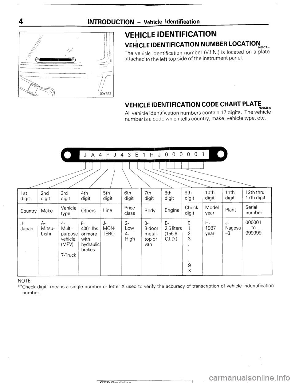
“&LE IDENTIFICATION NUMBER LOCATIOyo(lcAmm
The vehicle identification number (V.I.N.) is located on a plate
attached to the left top side of the instrument panel.
VEHICLE lDENTlFlCATlON CODE CHART PLATEo,,.,
All vehicle identification numbers contain 17 digits. The vehicle
number is a code which tells country, make, vehicle type, etc.
Country Make
!
J- A-
Japan Mitsu-
bishi Vehicle
type Line 4-
F- J-
Multi-
4001 Ibs. MON-
purpose or more TERO
vehicle
with
(MPW hydraulic
brakes
7-Truck
6th
digit
Price
class
2- Low
4- High 7th
8th 9th 10th
digit digit digit digit
Body Engine Check Model
digit year
3- E- 0 H-
3-door
2.6 liters 1 1987
metal- (155.9 2 year
top or C.I.D.) 3
van
9
X Plant
1 ZZ-Zer 1
NOTE
*“Check digit” means a single number or letter X used to verify the accuracy of transcription of vehicle indentification
number.
1 STB Revision
1 I : “’
Page 5 of 284
INTRODUCTION - Vehicle Identification
VEHICLE IDENTIFICATION NUMBER LIST
FEDERAL
VIN (except sequence number) Brand Engine displacement
JA4FJ43EoHJ
JA4FJ43EoHJ MITSUBISHI 2.555 liters
JA7FJ23EoHJ MONTERO (155.9 C.I.D.)
JA7FJ23EoHJ
5
NOOCC-
Model code
L042GVNJLF
L042GVRJLF
L042GTNSLF
L042GTRSLF
CALIFORNIA (Can also be sold in Federal states.)
VIN (except sequence number)
JA4FJ43EoHJ
JA4FJ43EoHJ
JA7FJ23EoHJ
JB7FJ23EoHJ Brand
MITSUBISHI
MONTERO Engine displacement
2.555 liters
(155.9 C.I.D.) Model code
L042GVNJLH
L042GVRJLH
L042GTNSLH
1 L042GTNSLH
OOK520
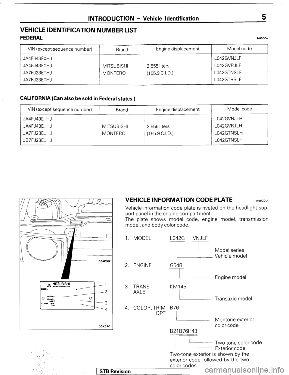
VEHICLE INFORMATION CODE PLATE NOOCO-A
Vehicle information code plate is riveted on the headlight sup-
port panel in the engine compartment.
The plate shows model code, engine model, transmission
model, and body color code.
1. MODEL L042G VNJLF
2. ENGINE G54B
I Engine model
3. TRANS
AXLE KM145
4. COLOR, TRIM
OPT 876
B2 1 B76H43
F
Two-tone exterior is shown by the Two-tone color code
Exterior code Transaxle model
Montone exterior
color code
exterior code followed by the two
color codes.
) STB Revision
._ :
Page 6 of 284
6 INTRODUCTION - Vehicle Identification
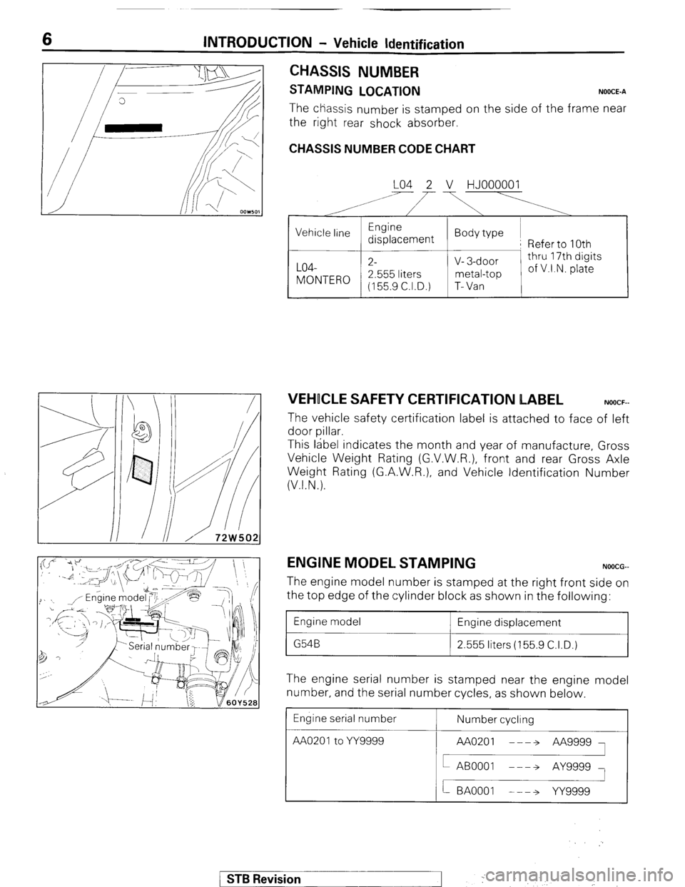
CHASSIS NUMBER
STAMPING LOCATION NOOCE-A
The chassis number is stamped on the side of the frame near
the right rear shock absorber.
CHASSIS NUMBER CODE CHART
LO4 2 V HJOOOOOl
A’ i’
,
VEHICLE SAFETY CERTIFICATION LABEL NOOCF-
The vehicle safety certification label is attached to face of left
door pillar.
This label indicates the month and year of manufacture, Gross
Vehicle Weight Rating (G.V.W.R.), front and rear Gross Axle
Weight Rating (G.A.W.R.), and Vehicle Identification Number
(V.I.N.).
ENGINE MODEL STAMPING NOOCG-
The engine model number is stamped at the right front side on
the top edge of the cylinder block as shown in the following:
1 Engine model
1 Engine displacement
1 2.555 liters (155.9 C.I.D.)
The engine serial number is stamped near the engine model
number, and the serial number cycles, as shown below
Engine serial number
AA020’toYY= Number cycling
/ STB Revision
--I f ,. ..-.
j ‘. .,
Page 9 of 284
INTRODUCTION - Precautions Before Service 9
nm (in.)
so0059
PARTS
When replacing parts, use MITSUBISHI genuine parts.
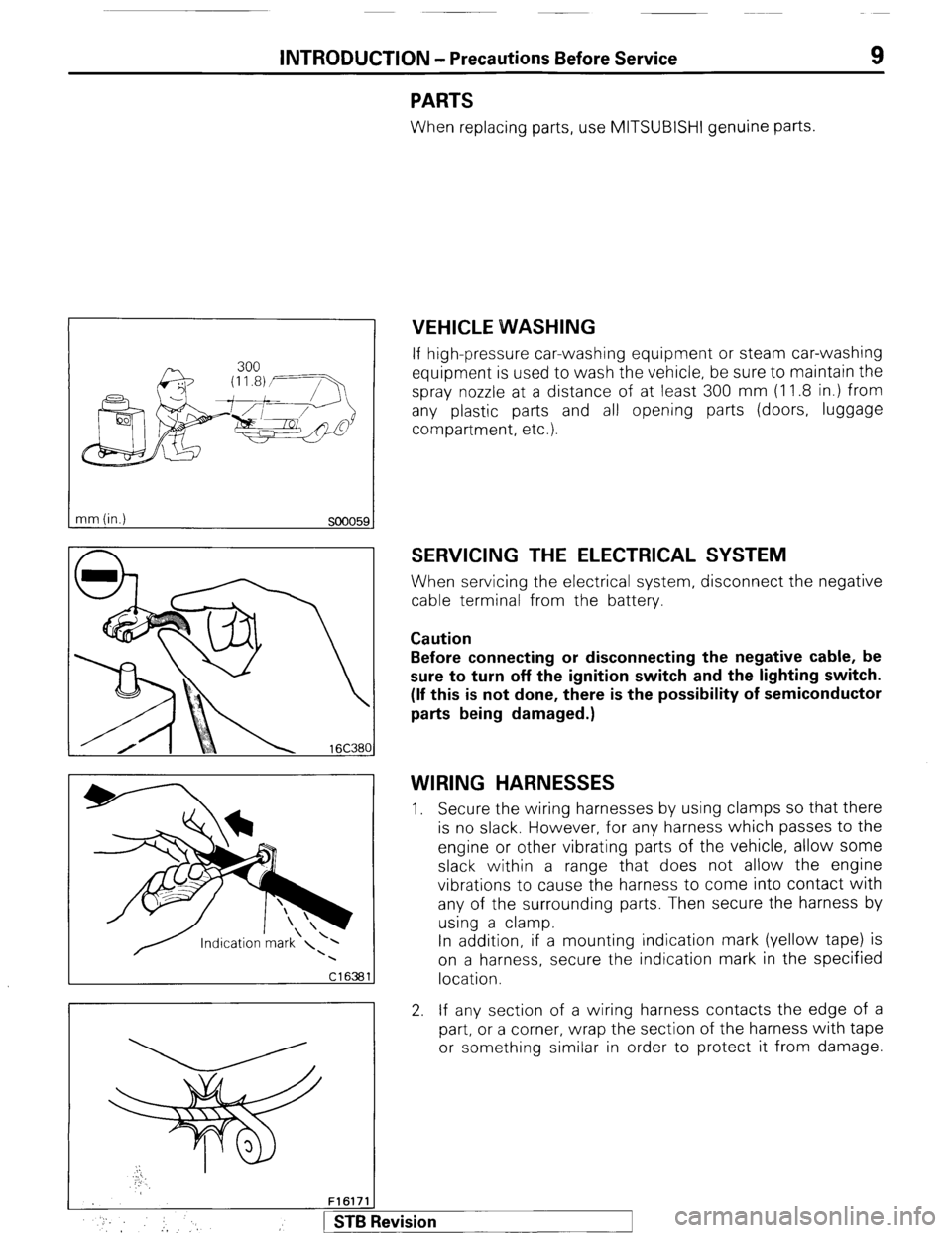
VEHICLE WVASHING
If high-pressure car-washing equipment or steam car-washing
equipment is used to wash the vehicle, be sure to maintain the
spray nozzle at a distance of at least 300 mm (1 1.8 in.) from
any plastic parts and all opening parts (doors, luggage
compartment, etc.).
SERVICING THE ELECTRICAL SYSTEM
When servicing the electrical system, disconnect the negative
cable terminal from the battery.
Caution
Before connecting or disconnecting the negative cable, be
sure to turn off the ignition switch and the lighting switch.
(If this is not done, there is the possibility of semiconductor
parts being damaged.)
WIRING HARNESSES
1. Secure the wiring harnesses by using clamps so that there
is no slack. However, for any harness which passes to the
engine or other vibrating parts of the vehicle, allow some
slack within a range that does not allow the engine
vibrations to cause the harness to come into contact with
any of the surrounding parts. Then secure the harness by
using a clamp.
In addition, if a mounting indication mark (yellow tape) is
on a harness, secure the indication mark in the specified
location.
2. If any section of a wiring harness contacts the edge of a
part, or a corner, wrap the section of the harness with tape
or something similar in order to protect it from damage.
F161711
* :, :, 1 STB Revision
Page 13 of 284
INTRODUCTION - Precautions Before Service 13
IKITE ON INSTALLATION OF RADIO EQUIPMW&
The computers of the electronic control system has been
designed so that external radio waves will not interfere with
their operation.
However, if antenna or cable of amateur transceiver etc. is
routed near the computers, it may affect the operation of the
computers, even if the output of the transceiver is no more
than 25W.
To protect each of the computers from interference by
transmitter (hum, transceiver, etc.), the following should be
observed.
1. Install the antenna on the roof.
2. Because radio waves are emitted from the coaxial cable of
the antenna, keep it 200 mm (8 in.) away from the
computers and the wiring harness. If the cable must cross
the wiring harness, route it so that it runs at right angles to
the wiring harness.
3. The antenna and the cable should be well matched, and
the standing-wave ratio* should be kept low.
4. A transmitter having a large output should not be installed
in the vehicle.
5. After installation of transmitter, run the engine at idle, emit
radio waves from the transmitter and make sure that the
engine is not affected.
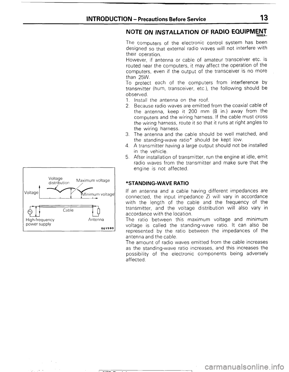
High-frequency power supply If an antenna and a cable having different impedances are
connected, the input impedance Zi will vary in accordance
with the length of the cable and the frequency of the
transmitter, and the voltage distribution will also vary in
accordance with the location.
The ratio between this maximum voltage and minimum
voltage is called the standing-wave ratio. It can also be
represented by the ratio between the impedances of the
antenna and the cable.
The amount of radio waves emitted from the cable increases
as the standing-wave ratio increases, and this increases the
possibility of the electronic components being adversely
affected.
_. r.
; ST6 Revision
Page 18 of 284
18 INTRODUCTION - General Data and Specifications
Description L042G VNJLFIH VRJ L.F/H TNSLFIH TRSLFIH
1
Engine
Model No. G54B
G54B G54B G54B
Type i In-line OHC
In-line OHC In-line OHC In-line OHC
Number of cylinders ‘4 4
4 4
Bore 91 .I mm (3.59 in.) 91 .I mm (3.59 in.) 91 ,I mm (3.59 in.) 91 .I mm (3.59 in.)
Stroke 98.0 mm (3.86 in.) 98.0 mm (3.86 in.) 98.0 mm (3.86 in.) 98.0 mm (3.86 in.)
Piston displacement
2,555 cm” 2,555 cm” 2,555 cm3
2,555 cm3
(155.9 CID) (155.9 CID) (155.9 CID) (155.9 CID)
Compression ratio 8.7
8.7 8.7
8.7
Firing order
I-3-4-2 I-3-4-2 1-3-4-2
1-3-4-2
Basic ignitron trming
7” BTDC ? 2” 7” BTDC ? 2” 7” BTDC 2 2” ‘7” BTDC ? 2”
Transmission &transfer case
Model No.
KM145 KM148 KM145 KM148
Type 5-speed 4-speed 5-speed 4-speed
manual automatic manual automatic
Cear ratio
Transmjssion 1 st
3.967 2.826 3.967
2.826
2nd
2.136 1.493 2.136
1.493
3rd 1.360
1 .ooo 1.360
1.000
4th
1.000 0.688 1 .ooo
0.688
5th
0.856 - 0.856
-
Reverse 3.578
2.703 3.578
2.703
Transfer case High 1.000
1.000 1.000
1 ,040
Low 1.944
1.944 1.944
1.944
Final ring ratio
gear 4.625 4.625 4.625
4.625
Zlutch
Type Dry single
- Dry single
-
disc & disc &
diaphragm diaphragm
spring spring
Chassis
Tire size
Front suspension
P225/75R15
Type
Spring constant
(Wheel position)
Rear suspension
Type
Spring constant
At load of 1 ,OOO-2,500 N
(220-551 Ibs.)
At load of 4,670-8,870 N
(1,030-I ,955 tbs.) Wishbone compression type
22 N/mm (123 Ibs./in.)
Asymmetrical semi-elliptic leaf spring
22 N/mm (123 Ibs./in.)
50 N/mm (280 Ibs./in.)
1 STB Revision ..,j ; : * :
Page 38 of 284
WIRING HARNESS - Troubleshooting
1660236
Power
supply
h
Fuse
ON
/----
/
/
Motor
1660239
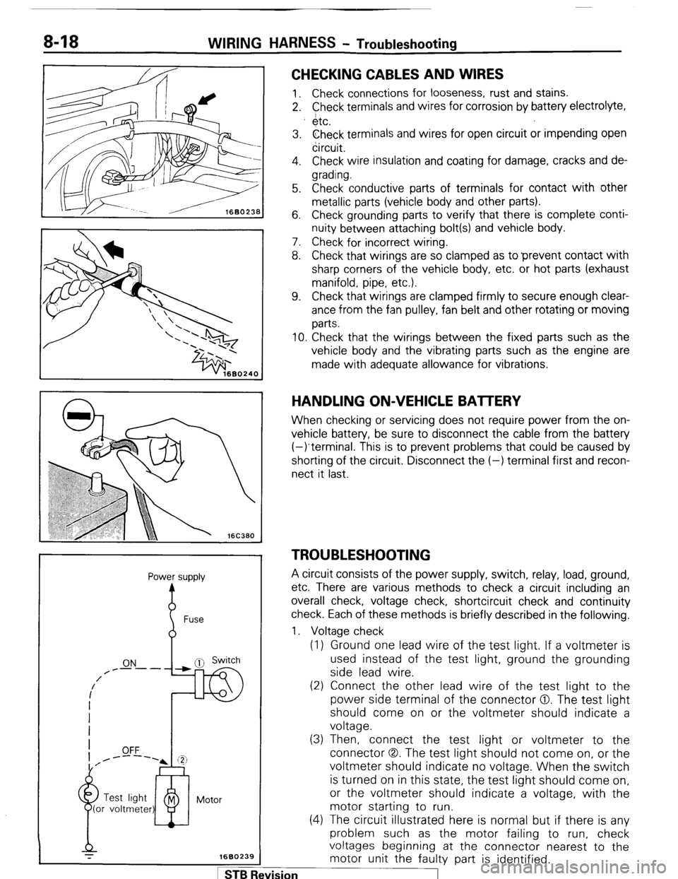
CHECKING CABLES AND WIRES
1. Check connections for looseness, rust and stains.
2. Check terminals and wires for corrosion by battery electrolyte,
$tc.
3. Check terminals and wires for open circuit or impending open
circuit.
4. Check wire insulation and coating for damage, cracks and de-
grading.
5. Check conductive parts of terminals for contact with other
metallic parts (vehicle body and other parts).
6. Check grounding parts to verify that there is complete conti-
nuity between attaching bolt(s) and vehicle body.
7. Check for incorrect wiring.
8. Check that wirings are so clamped as to ‘prevent contact with
sharp corners of the vehicle body, etc. or hot parts (exhaust
manifold, pipe, etc.).
9. Check that wirings are clamped firmly to secure enough clear-
ance from the fan pulley, fan belt and other rotating or moving
parts.
10. Check that the wirings between the fixed parts such as the
vehicle body and the vibrating parts such as the engine are
made with adequate allowance for vibrations.
HANDLING ON-VEHICLE BAlTERY
When checking or servicing does not require power from the on-
vehicle battery, be sure to disconnect the cable from the battery
(-)terminal. This is to prevent problems that could be caused by
shorting of the circuit. Disconnect the (-) terminal first and recon-
nect it last.
TROUBLESHOOTING
A circuit consists of the power supply, switch, relay, load, ground,
etc. There are various methods to check a circuit including an
overall check, voltage check, shortcircuit check and continuity
check. Each of these methods is briefly described in the following.
1. Voltage check
(1) Ground one lead wire of the test light. If a voltmeter is
used instead of the test light, ground the grounding
side lead wire.
(2) Connect the other lead wire of the test light to the
power side terminal of the connector 0. The test light
should come on or the voltmeter should indicate a
voltage.
(3) Then, connect the test light or voltmeter to the
connector (3,. The test light should not come on, or the
voltmeter should indicate no voltage. When the switch
is turned on in this state, the test light should come on,
or the voltmeter should indicate a voltage, with the
motor starting to run.
(4) The circuit illustrated here is normal but if there is any
problem such as the motor failing to run, check
voltages beginning at the connector nearest to the
motor unit the faulty part is identified. 1 ST6 Revision
Page 40 of 284
8-20 WIRING HARNESS - How to Read Wiring Diagrams
HOW TO READ WIRING DIAGRAM NOEDBAE
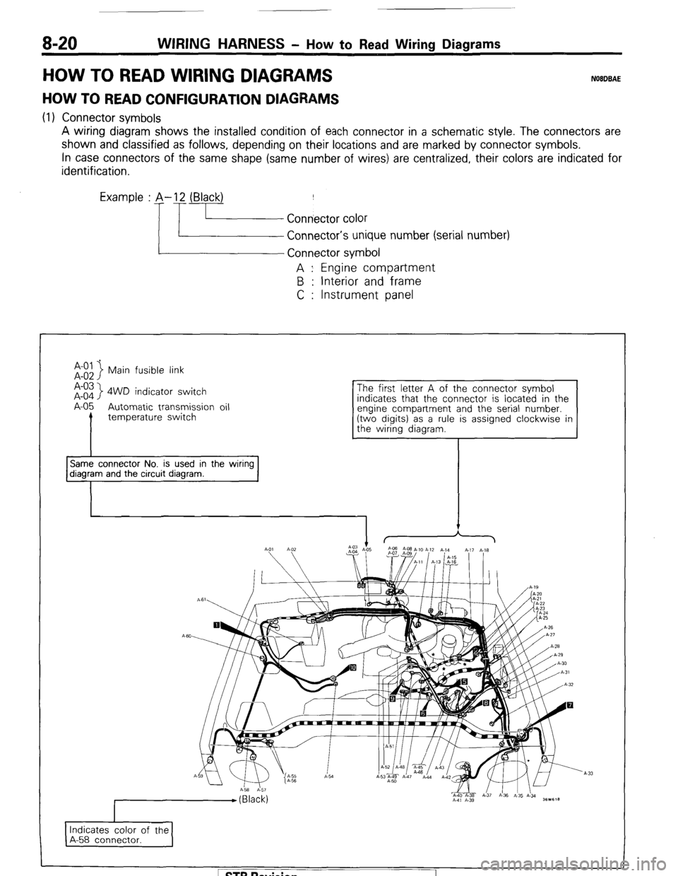
HOW TO READ CONFIGURATION DIAGRAMS
(1) Connector symbols
A wiring diagram shows the installed condition of each connector in a schematic style. The connectors are
shown and classified as follows, depending on their locations and are marked by connector symbols.
In case connectors of the same shape (same number of wires) are centralized, their colors are indicated for
identification.
Examp’e : p.!- f.~~~~ ~;~~o,
Connector’s unique number (serial number)
A : Engine compartment
B : Interior and frame
C : Instrument panel
Main fusible link
A-03
A-o4
> 4WD indicator switch
A-05 Automatic transmission oil
I temperature switch indicates that the connector is located in the
Same connector No. is used in the wiring diagram and the circuit diagram.
I Indicates color of the
A-58 connector. I
1 ST6 Revision