engine MITSUBISHI MONTERO 1998 Service Manual
[x] Cancel search | Manufacturer: MITSUBISHI, Model Year: 1998, Model line: MONTERO, Model: MITSUBISHI MONTERO 1998Pages: 1501, PDF Size: 25.81 MB
Page 545 of 1501
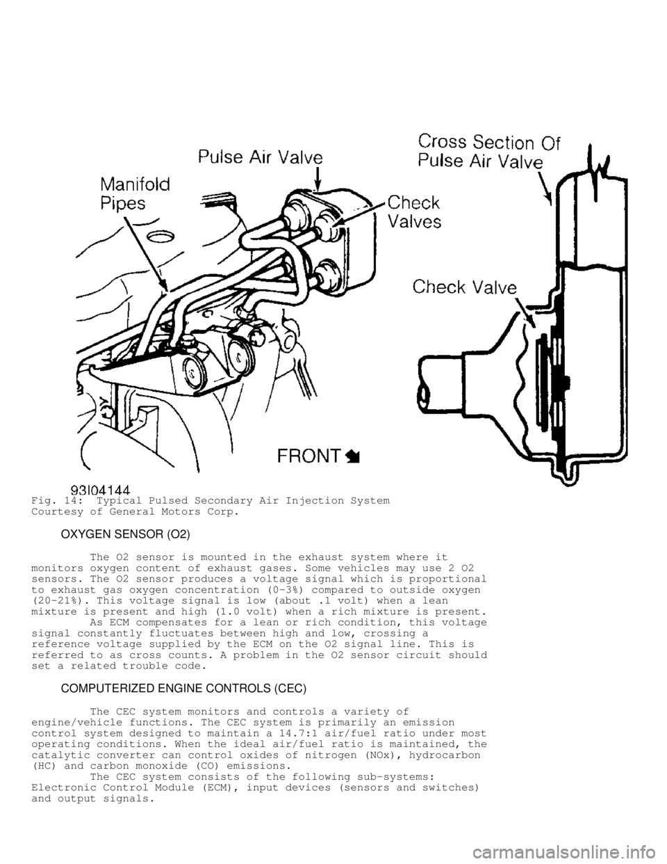
Fig. 14: Typical Pulsed Secondary Air Injection System
Courtesy of General Motors Corp.
OXYGEN SENSOR (O2)
The O2 sensor is mounted in the exhaust system where it
monitors oxygen content of exhaust gases. Some vehicles may use 2 O2
sensors. The O2 sensor produces a voltage signal which is proportional
to exhaust gas oxygen concentration (0-3%) compared to outside oxygen
(20-21%). This voltage signal is low (about .1 volt) when a lean
mixture is present and high (1.0 volt) when a rich mixture is present.\
As ECM compensates for a lean or rich condition, this voltage
signal constantly fluctuates between high and low, crossing a
reference voltage supplied by the ECM on the O2 signal line. This is
referred to as cross counts. A problem in the O2 sensor circuit should
set a related trouble code.
COMPUTERIZED ENGINE CONTROLS (CEC)
The CEC system monitors and controls a variety of
engine/vehicle functions. The CEC system is primarily an emission
control system designed to maintain a 14.7:1 air/fuel ratio under most
operating conditions. When the ideal air/fuel ratio is maintained, the
catalytic converter can control oxides of nitrogen (NOx), hydrocarbon
(HC) and carbon monoxide (CO) emissions.
The CEC system consists of the following sub-systems:
Electronic Control Module (ECM), input devices (sensors and switches)\
and output signals.
Page 546 of 1501
EARLY FUEL EVAPORATION (EFE)
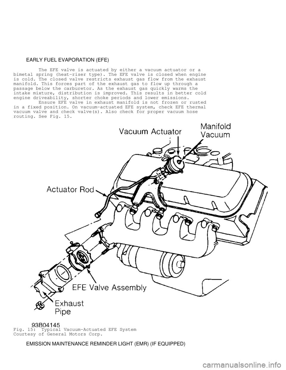
The EFE valve is actuated by either a vacuum actuator or a
bimetal spring (heat-riser type). The EFE valve is closed when engine
is cold. The closed valve restricts exhaust gas flow from the exhaust
manifold. This forces part of the exhaust gas to flow up through a
passage below the carburetor. As the exhaust gas quickly warms the
intake mixture, distribution is improved. This results in better cold
engine driveability, shorter choke periods and lower emissions.
Ensure EFE valve in exhaust manifold is not frozen or rusted
in a fixed position. On vacuum-actuated EFE system, check EFE thermal
vacuum valve and check valve(s). Also check for proper vacuum hose
routing. See Fig. 15.
Fig. 15: Typical Vacuum-Actuated EFE System
Courtesy of General Motors Corp.
EMISSION MAINTENANCE REMINDER LIGHT (EMR) (IF EQUIPPED)
Page 547 of 1501

If equipped, the EMR light (some models may use a reminder
flag) reminds vehicle operator that an emission system maintenance is
required. This indicator is activated after a predetermined
time/mileage.
When performing a smog check inspection, ensure EMR indicator
is not activated. On models using an EMR light, light should glow when
ignition switch is turned to ON position and should turn off when
engine is running.
If an EMR flag is present or an EMR light stays on with
engine running, fail vehicle and service or replace applicable
emission-related components. To reset an EMR indicator, refer to
appropriate MAINTENANCE REMINDER LIGHTS in the MAINTENANCE section.
MALFUNCTION INDICATOR LIGHT (MIL)
The Malfunction Indicator Light (MIL) is used to alert
vehicle operator that the computerized engine control system has
detected a malfunction (when it stays on all the time with engine
running). On some models, the MIL may also be used to display trouble
codes.
As a bulb and system check, malfunction indicator light will
glow when ignition switch is turned to ON position and engine is not
running. When engine is started, light should go out.
Page 548 of 1501

ENGINE OVERHAUL PROCEDURES - GENERAL INFORMATION
1998 Mitsubishi Montero
Engine Overhaul Procedures - General Information
ALL PISTON ENGINES
* PLEASE READ THIS FIRST *
Examples used in this article are general in nature and do
not necessarily relate to a specific engine or system. Illustrations
and procedures have been chosen to guide mechanic through engine
overhaul process. Descriptions of processes of cleaning, inspection,
assembly and machine shop practice are included.
Always refer to appropriate engine overhaul article in the
ENGINES section for complete overhaul procedures and specifications
for the vehicle being repaired.
ENGINE IDENTIFICATION
The engine may be identified from its Vehicle Identification
Number (VIN) stamped on a metal tab. Metal tab may be located in
different locations depending on manufacturer. Engine identification
number or serial number is located on cylinder block. Location varies
with manufacturer.
INSPECTION PROCEDURES
* PLEASE READ THIS FIRST *
NOTE: Always refer to appropriate engine overhaul article in the
ENGINES section for complete overhaul procedures and
specifications for the vehicle being repaired.
GENERAL
Engine components must be inspected to meet manufacturer's
specifications and tolerances during overhaul. Proper dimensions and
tolerances must be met to obtain proper performance and maximum engine
life.
Micrometers, depth gauges and dial indicator are used for
checking tolerances during engine overhaul. Magnaflux, Magnaglo, dye-
check, ultrasonic and x-ray inspection procedures are used for parts
inspection.
MAGNETIC PARTICLE INSPECTION
Magnaflux & Magnaglo
Magnaflux is an inspection technique used to locate material
flaws and stress cracks. The part in question is subjected to a strong
magnetic field. The entire part, or a localized area, can be
magnetized. The part is coated with either a wet or dry material that
contains fine magnetic particles.
Cracks which are outlined by the particles cause an
interruption in the magnetic field. The dry powder method of Magnaflux
can be used in normal light. A crack will appear as an obvious bright
line.
Fluorescent liquid is used in conjunction with a blacklight
in a second Magnaflux system called Magnaglo. This type of inspection
demands a darkened room. The crack will appear as a glowing line in
this process. Both systems require complete demagnetizing upon
Page 549 of 1501

completion of the inspection. Magnetic particle inspection applies to
ferrous materials only.
PENETRANT INSPECTION
Zyglo
The Zyglo process coats the material with a fluorescent dye
penetrant. The part is often warmed to expand cracks that will be
penetrated by the dye. When the coated part is subjected to inspection
with a blacklight, a crack will glow brightly. Developing solution
is often used to enhance results. Parts made of any material, such as
aluminum cylinder heads or plastics, may be tested using this process.
Dye Check
Penetrating dye is sprayed on the previously cleaned
component. Dye is left on component for 5-45 minutes, depending upon
material density. Component is then wiped clean and sprayed with a
developing solution. Surface cracks will show up as a bright line.
ULTRASONIC INSPECTION
If an expensive part is suspected of internal cracking,
Ultrasonic testing is used. Sound waves are used for component
inspection.
X-RAY INSPECTION
This form of inspection is used on highly stressed
components. X-ray inspection maybe used to detect internal and
external flaws in any material.
PRESSURE TESTING
Cylinder heads can be tested for cracks using a pressure
tester. Pressure testing is performed by plugging all but one of the
holes in the head and injecting air or water into the open passage.
Leaks are indicated by the appearance of wet or damp areas when using
water. When air is used, it is necessary to spray the head surface
with a soap solution. Bubbles will indicate a leak. Cylinder head may
also be submerged in water heated to specified temperature to check
for cracks created during heat expansion.
CLEANING PROCEDURES
* PLEASE READ THIS FIRST *
NOTE: Always refer to appropriate engine overhaul article in the
ENGINES section for complete overhaul procedures and
specifications for the vehicle being repaired.
GENERAL
All components of an engine do not have the same cleaning
requirements. Physical methods include bead blasting and manual
removal. Chemical methods include solvent blast, solvent tank, hot
tank, cold tank and steam cleaning of components.
BEAD BLASTING
Manual removal of deposits may be required prior to bead
blasting, followed by some other cleaning method. Carbon, paint and
Page 550 of 1501

rust may be removed using bead blasting method. Components must be
free of oil and grease prior to bead blasting. Beads will stick to
grease or oil soaked areas causing area not to be cleaned.
Use air pressure to remove all trapped residual beads from
components after cleaning. After cleaning internal engine parts made
of aluminum, wash thoroughly with hot soapy water. Component must be
thoroughly cleaned as glass beads will enter engine oil resulting in
bearing damage.
CHEMICAL CLEANING
Solvent tank is used for cleaning oily residue from
components. Solvent blasting sprays solvent through a siphon gun using
compressed air.
The hot tank, using heated caustic solvents, is used for
cleaning ferrous materials only. DO NOT clean aluminum parts such as
cylinder heads, bearings or other soft metals using the hot tank.
After cleaning, flush parts with hot water.
A non-ferrous part will be ruined and caustic solution will
be diluted if placed in the hot tank. Always use eye protection and
gloves when using the hot tank.
Use of a cold tank is for cleaning of aluminum cylinder
heads, carburetors and other soft metals. A less caustic and unheated
solution is used. Parts may be lift in the tank for several hours
without damage. After cleaning, flush parts with hot water.
Steam cleaning, with boiling hot water sprayed at high
pressure, is recommended as the final cleaning process when using
either hot or cold tank cleaning.
COMPONENT CLEANING
* PLEASE READ THIS FIRST *
NOTE: Always refer to appropriate engine overhaul article in the
ENGINES section for complete overhaul procedures and
specifications for the vehicle being repaired.
SHEET METAL PARTS
Examples of sheet metal parts are the rocker covers, front
and side covers, oil pan and bellhousing dust cover. Glass bead
blasting or hot tank may be used for cleaning.
Ensure all mating surfaces are flat. Deformed surfaces should
be straightened. Check all sheet metal parts for cracks and dents.
INTAKE & EXHAUST MANIFOLDS
Using solvent cleaning or bead blasting, clean manifolds for
inspection. If the intake manifold has an exhaust crossover, all
carbon deposits must be removed. Inspect manifolds for cracks, burned
or eroded areas, corrosion and damage to fasteners.
Exhaust heat and products of combustion cause threads of
fasteners to corrode. Replace studs and bolts as necessary. On "V"
type intake manifolds, the sheet metal oil shield must be removed for
proper cleaning and inspection. Ensure that all manifold parting
surfaces are flat and free of burrs.
CYLINDER HEAD REPLACEMENT
* PLEASE READ THIS FIRST *
Page 551 of 1501
NOTE: Always refer to appropriate engine overhaul article in the
ENGINES section for complete overhaul procedures and
specifications for the vehicle being repaired.
REMOVAL
Remove intake and exhaust manifolds and valve cover. Cylinder
head and camshaft carrier bolts (if equipped), should be removed only
when the engine is cold. On many aluminum cylinder heads, removal
while hot will cause cylinder head warpage. Mark rocker arm or
overhead cam components for location.
Remove rocker arm components or overhead cam components.
Components must be installed in original location. Individual design
rocker arms may utilize shafts, ball-type pedestal mounts or no rocker
arms. For all design types, wire components together and identify
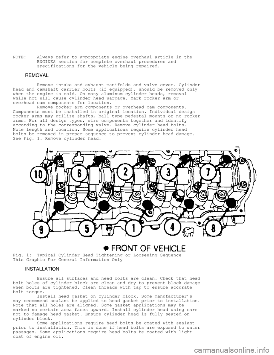
according to the corresponding valve. Remove cylinder head bolts.
Note length and location. Some applications require cylinder head
bolts be removed in proper sequence to prevent cylinder head damage.
See Fig. 1 . Remove cylinder head.
Fig. 1: Typical Cylinder Head Tightening or Loosening Sequence
This Graphic For General Information Only
INSTALLATION
Ensure all surfaces and head bolts are clean. Check that head
bolt holes of cylinder block are clean and dry to prevent block damage
when bolts are tightened. Clean threads with tap to ensure accurate
bolt torque.
Install head gasket on cylinder block. Some manufacturer's
may recommend sealant be applied to head gasket prior to installation.
Note that all holes are aligned. Some gasket applications may be
marked so certain area faces upward. Install cylinder head using care
not to damage head gasket. Ensure cylinder head is fully seated on
cylinder block.
Some applications require head bolts be coated with sealant
prior to installation. This is done if head bolts are exposed to water
passages. Some applications require head bolts be coated with light
coat of engine oil.
Page 552 of 1501

Install head bolts. Head bolts should be tightened in proper
steps and sequence to specification. See Fig. 1. Install remaining
components. Tighten all bolts to specification. Adjust valves if
required. See VALVE ADJUSTMENT in this article.
NOTE: Some manufacturers require that head bolts be retightened
after specified amount of operation. This must be done to
prevent head gasket failure.
VALVE ADJUSTMENT
Engine specifications will indicate valve train clearance and
temperature at which adjustment is to be made on most models. In most
cases, adjustment will be made with a cold engine. In some cases, both
a cold and a hot clearance will be given for maintenance convenience.
On some models, adjustment is not required. Rocker arms are
tightened to specification and valve lash is automatically set. On
some models with push rod actuated valve train, adjustment is made at
push rod end of rocker arm while other models do not require
adjustment.
Clearance will be checked between tip of rocker arm and tip
of valve stem in proper sequence using a feeler gauge. Adjustment is
made by rotating adjusting screw until proper clearance is obtained.
Lock nut is then tightened. Engine will be rotated to obtain all valve
adjustments to manufacturer's specifications.
Some models require hydraulic lifter to be bled down and
clearance measured. Different length push rods can be used to obtain
proper clearance. Clearance will be checked between tip of rocker arm
and tip of valve stem in proper sequence using a feeler gauge.
On overhead cam engines designed without rocker arms actuate
valves directly on a cam follower. A hardened, removable disc is
installed between the cam lobe and lifter. Clearance will be checked
between cam heel and adjusting disc in proper sequence using a feeler
gauge. Engine will be rotated to obtain all valve adjustments.
On overhead cam engines designed with rocker arms, adjustment
is made at push rod end of rocker arm. Ensure that the valve to be
adjusted is riding on the heel of the cam on all engines. Clearance
will be checked between tip of rocker arm and tip of valve stem in
proper sequence using a feeler gauge. Adjustment is made by rotating
adjusting screw until proper clearance is obtained. Lock nut is then
tightened. Engine will be rotated to obtain all valve adjustments to
manufacturer's specifications.
CYLINDER HEAD OVERHAUL
* PLEASE READ THIS FIRST *
NOTE: Always refer to appropriate engine overhaul article in the
ENGINES section for complete overhaul procedures and
specifications for the vehicle being repaired.
DISASSEMBLY
Mark valves for location. Using valve spring compressor,
compress valve springs. Remove valve locks. Carefully release spring
compressor. Remove retainer or rotator, valve spring, spring seat and
valve. See Fig. 2.
Page 554 of 1501
On cast cylinder heads, if warpage exceeds .003" (.08 mm)
in a 6" span, or .006" (.15 mm) over total length, cylinder head must
be resurfaced. On most aluminum cylinder heads, if warpage exceeds .
002" (.05 mm) in any area, cylinder head must be resurfaced. Warpage
specification may vary with manufacturer.
Cylinder head thickness should be measured to determine
amount of material which can be removed before replacement is
required. Cylinder head thickness must not be less than manufacturer's
specifications.
If cylinder head required resurfacing, it may not align
properly with intake manifold. On "V" type engines, misalignment is
corrected by machining intake manifold surface that contacts cylinder
head. Cylinder head may be machined on surface that contacts intake
manifold.
Using oil stone, remove burrs or scratches from all sealing
surfaces.
VALVE SPRINGS
Inspect valve springs for corroded or pitted valve spring
surfaces which may lead to breakage. Polished spring ends caused by
a rotating spring, indicates that spring surge has occurred. Replace
springs showing evidence of these conditions.
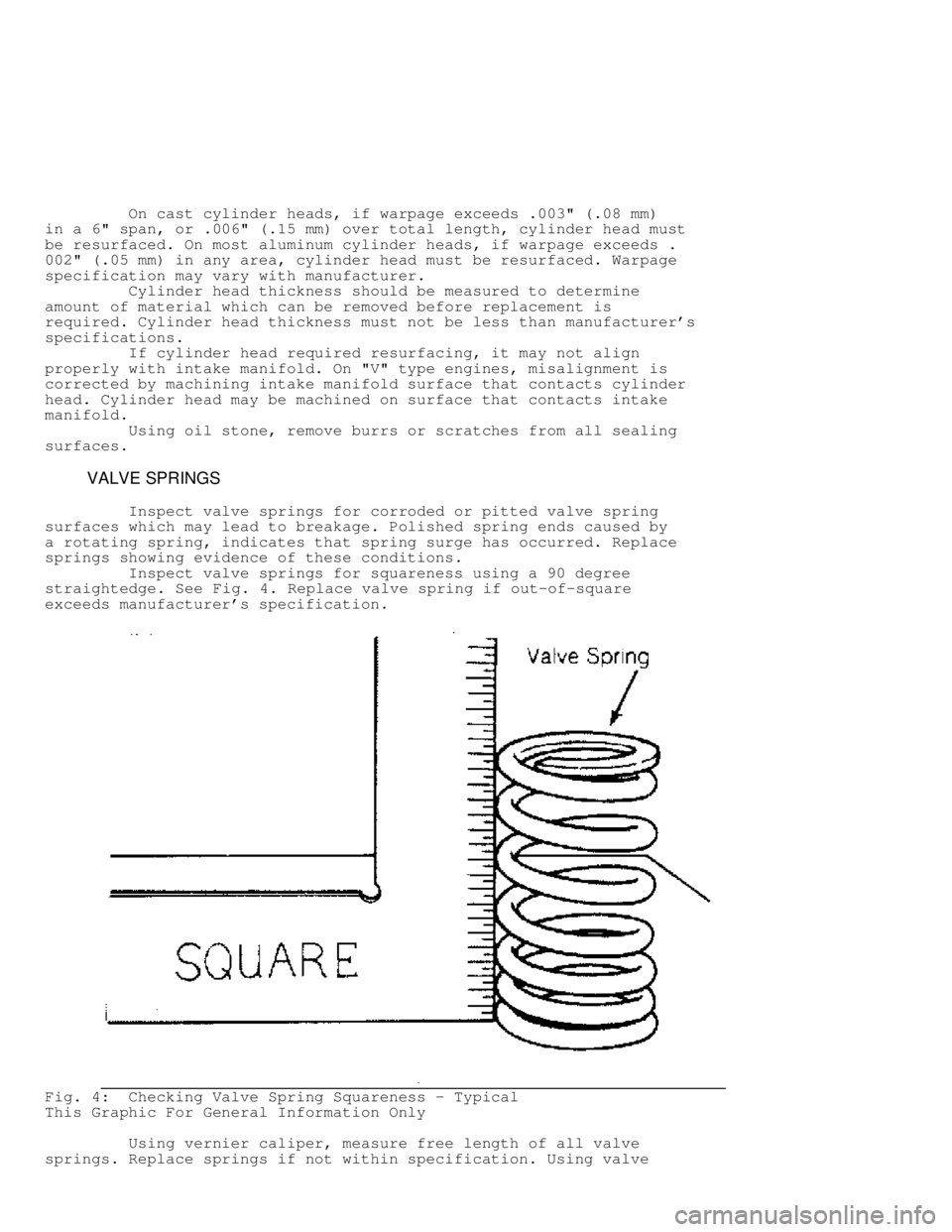
Inspect valve springs for squareness using a 90 degree
straightedge. See Fig. 4. Replace valve spring if out-of-square
exceeds manufacturer's specification.
Fig. 4: Checking Valve Spring Squareness - Typical
This Graphic For General Information Only
Using vernier caliper, measure free length of all valve
springs. Replace springs if not within specification. Using valve
Page 559 of 1501
during manufacture, some new type valves cannot be reground.
Resurface valve on proper angle specification using valve
grinding machine. Follow manufacturer's instructions for valve
grinding machine. Specifications may indicate a different valve face
angle than seat angle.
Measure valve margin after grinding. Replace valve if not
within specification. Valve stem tip can be refinished using valve
grinding machine.
Valve Lapping
During valve lapping of recent designed valves, be sure to
follow manufacturers recommendations. Surface hardening and materials
used with some valves do not permit lapping. Lapping process will
remove excessive amounts of the hardened surface.
Valve lapping is done to ensure adequate sealing between
valve face and seat. Use either a hand drill or lapping stick with
suction cup attached.
Moisten and attach suction cup to valve. Lubricate valve stem
and guide. Apply a thin coat of fine valve grinding compound between
valve and seat. Rotate lapping tool between the palms or with hand
drill.
Lift valve upward off the seat and change position often.
This is done to prevent grooving of valve seat. Lap valve until a
smooth polished seat is obtained. Thoroughly clean grinding compound
from components. Valve to valve seat concentricity should be checked.
See VALVE SEAT CONCENTRICITY.
CAUTION: Valve guides must be in good condition and free of carbon
deposits prior to valve seat grinding. Some engines contain
an induction hardened valve seat. Excessive material removal
will damage valve seats.
Valve Seat Grinding
Select coarse stone of correct size and angle for seat to be
ground. Ensure stone is true and has a smooth surface. Select correct
size pilot for valve guide dimension. Install pilot in valve guide.
Lightly lubricate pilot shaft. Install stone on pilot. Move stone off
and on the seat approximately 2 times per second during grinding
operation.
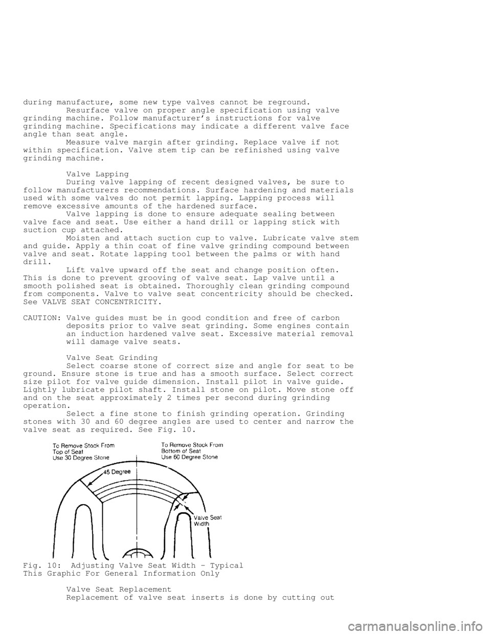
Select a fine stone to finish grinding operation. Grinding
stones with 30 and 60 degree angles are used to center and narrow the
valve seat as required. See Fig. 10.
Fig. 10: Adjusting Valve Seat Width - Typical
This Graphic For General Information Only
Valve Seat Replacement
Replacement of valve seat inserts is done by cutting out