fuel pressure MITSUBISHI MONTERO 2000 Service Owners Manual
[x] Cancel search | Manufacturer: MITSUBISHI, Model Year: 2000, Model line: MONTERO, Model: MITSUBISHI MONTERO 2000Pages: 1839, PDF Size: 29.19 MB
Page 658 of 1839

DIESEL FUEL <4D5-stepIII>-Troubleshooting13E-48
Terminal
No.Normal condition: Inspection conditions (engine status) Check item
88Boost air temperature
sensorIgnition switch: ONIntake air temperature:
0_C3.2 - 3.8 V
Intake air temperature:
20_C2.3 - 2.9 V
Intake air temperature:
40_C1.4 - 2.0 V
Intake air temperature:
80_C0.4 - 1.0 V
89Crank angle sensorEngine: Idling (Use a digital voltage meter to check.)0V↔5V
(repeat the change)
90EGR valve position
sensor
Engine: After warm-
inguptheengine
Idling under no load2.3 - 3.3 V
sensoring up the engineEngine is suddenly racedMomentarily drops from
voltage during idling
91Parking switchIgnition switch: ON
(Enginestops)
Parking brake: ON0-1V
(Engine stops)Parking brake: OFFSystem voltage
CHECK CHART FOR RESISTANCE AND CONTINUITY
BETWEEN TERMINALS
1. Turn the ignition switch to LOCK (OFF) position.
2. Disconnect the engine-ECU connector.
3. Measure the resistance and check for continuity between
the terminals of the engine-ECU harness-side connector
while referring to the check chart.
NOTE
(1) When measuring resistance and checking continuity,
a harness for checking contact pin pressure should
be used instead of inserting a test probe.
(2) Checking need not be carried out in the order given
in the chart.
Caution
If the terminals that should be checked are mistaken,
or if connector terminals are not correctly shorted
to earth, damage may be caused to the vehicle wiring,
sensors, engine-ECU and/or ohmmeter.
Be careful to prevent this!
4. If the ohmmeter shows any deviation from the standard
value, check the corresponding sensor, actuator and
related electrical wiring, and then repair or replace.
5. After repair or replacement, recheck with the ohmmeter
to confirm that the repair or replacement has corrected
the problem.
www.WorkshopManuals.co.uk
Purchased from www.WorkshopManuals.co.uk
Page 735 of 1839

INTAKE AND EXHAUST -General Information/Service Specifications/Sealant15-3
At starting and driving at low speed, the duty control
value of the variable geometry solenoid valve is
increased to apply the vacuum pressure of the
vacuum pump to the variable geometry actuator.
Applying the vacuum pressure to the variable
geometry actuator pulls the actuator rod so that
it can move towards the direction of closing the
variable nozzle of the variable geometry
turbocharger. As closing the nozzle reduces the
exhaust gas mass, the speed of exhaust gas flow
will be increased and efficiency will be improved.
Since the characteristic of boost pressure becomes
a low speed type, boost pressure will suddenly
rise from low speed.
At driving at high speed, the duty control value
of the variable geometry solenoid valve is
decreased to reduce the vacuum pressure from
the vacuum pump so that the actuator rod can
return to the deactivated status and move towards
the direction of opening the nozzle of the variable
geometry turbocharger.Opening the nozzle allows the characteristic of
boost pressure to become a high speed type so
that the appropriate boost pressure can be
maintained.
Therefore, boost pressure can be controlled by
appropriate duty control of the variable geometry
solenoid valve. The engine-ECU calculates the
correct boost pressure based on the engine speed
and fuel injection amount. Furthermore, the duty
control of the variable geometry solenoid valve is
given feedback of the signals from the variable
geometry control pressure sensor and the boost
pressure sensor so that the variable nozzle opening
angle of the variable geometry turbocharger can
be quickly adjusted to obtain the desired boost
pressure.
SERVICE SPECIFICATIONS
ItemsStandard value
Variable geometry actuator activation vacuum
(Approximately 1 mm stroke) kPaApproximately 10.5 - 12.5
Variable geometry solenoid valve coil resistance
(at 20°C)Ω29 - 35
SEALANT
ItemSpecified sealantRemarks
Thread of the intake manifold mounting
bolts3M Stud Locking No.4170 or equivalentAnaerobic sealant
www.WorkshopManuals.co.uk
Purchased from www.WorkshopManuals.co.uk
Page 950 of 1839
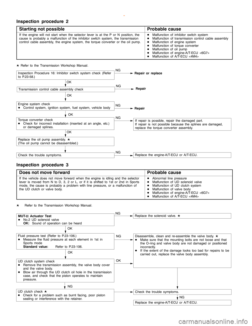
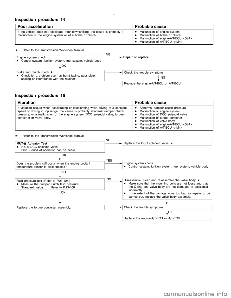
Page 952 of 1839
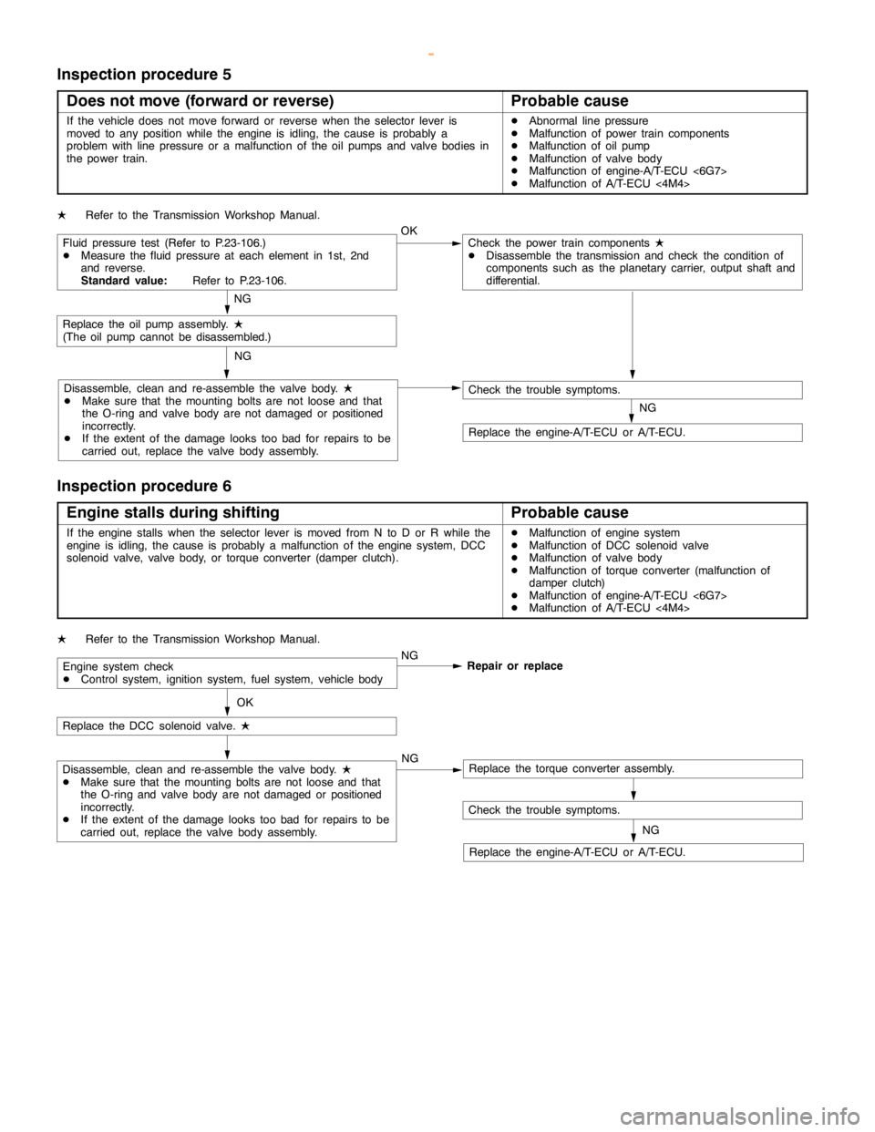
AUTOMATIC TRANSMISSION -Troubleshooting AUTOMATIC TRANSMISSION -Troubleshooting 23-51
Inspection procedure 5
Does not move (forward or reverse)
Probable cause
If the vehicle does not move forward or reverse when the selector lever is
moved to any position while the engine is idling, thecause is probably a
problem with line pressure or a malfunction of the oil pumps and valve bodies in
the power train.DAbnormal line pressure
DMalfunction of power train components
DMalfunction of oil pump
DMalfunction of valve body
DMalfunction of engine-A/T-ECU <6G7>
DMalfunction of A/T-ECU<4M4>
LRefer to the Transmission Workshop Manual.
Fluid pressure test (Refer to P.23-106.)
DMeasure the fluid pressure at each element in 1st, 2nd
and reverse.
Standard value:Refer to P.23-106.OKCheck the power train components
L
DDisassemble the transmission and check the condition of
components such as the planetary carrier, output shaft and
differential.
NG
Replace the oil pumpassembly.
L
(The oilpump cannot be disassembled.)
Disassemble, clean and re-assemble the valve body.
L
DMake sure that the mounting bolts are not loose and that
the O-ring and valve body are notdamaged or positioned
incorrectly.
DIf the extent of thedamagelooks too bad for repairs to be
carried out, replace the valve body assembly.NG
NG
Check the trouble symptoms.
Replace the engine-A/T-ECU or A/T-ECU.
Inspection procedure 6
Engine stalls during shifting
Probable cause
If the enginestalls when the selector lever is moved from N to D or R while the
engine is idling, thecause is probably a malfunction of theenginesystem, DCC
solenoid valve, valve body, or torque converter (damper clutch).DMalfunction of enginesystem
DMalfunction of DCC solenoid valve
DMalfunction of valve body
DMalfunction of torque converter (malfunction of
damper clutch)
DMalfunction of engine-A/T-ECU <6G7>
DMalfunction of A/T-ECU<4M4>
LRefer to the Transmission Workshop Manual.
Engine system check
DControl system, ignition system, fuel system, vehicle bodyNG
Repair or replace
OK
Replace the DCC solenoid valve.
L
Disassemble, clean and re-assemble the valve body.
L
DMake sure that the mounting bolts are not loose and that
the O-ring and valve body are notdamaged or positioned
incorrectly.
DIf the extent of thedamagelooks too bad for repairs to be
carried out, replace the valve body assembly.NGReplace the torque converter assembly.
Check the trouble symptoms.
Replace the engine-A/T-ECU or A/T-ECU.NG
www.WorkshopManuals.co.uk
Purchased from www.WorkshopManuals.co.uk
Page 958 of 1839