fuel pressure MITSUBISHI MONTERO 2000 Service Manual PDF
[x] Cancel search | Manufacturer: MITSUBISHI, Model Year: 2000, Model line: MONTERO, Model: MITSUBISHI MONTERO 2000Pages: 1839, PDF Size: 29.19 MB
Page 557 of 1839

DIESEL FUEL <4M4> -General/Service Specifications/Troubleshooting13C-2
GENERAL
OUTLINE OF CHANGES
Some service procedures have been established as the following changes have been made due to the
compliance with the Emission Regulation StepIII.
DThe intake manifold cover and injection pump cover have been reshaped.
DThe throttle body assembly has been changed.
DThe EGR valve assembly has been changed.
SERVICE SPECIFICATIONS
ItemStandard value
Throttle body assembly resistanceΩat - 10 - 50_C12 - 20
at 50 - 100_C12 - 23
TROUBLESHOOTING
FAIL-SAFE, BACKUP FUNCTIONS
When abnormalities in the major sensors are detected by diagnosis functions, pre-set control logic operates
to maintain a safe driving condition for the vehicle.
Diagnosis itemControl features in malfunction
Accelerator pedal position sensorDAccelerator pedal released (idle switch ON)
Acceleration opening degree = 0 %
DAccelerator pedal applied (idle switch OFF)
Engine controlled at low speed
Acceleration opening degree = 40 %
DVoid cruise control
Idle switchDVoid idling speed control
DVoid cruise control
Engine speed sensorDEngine controlled at low speed
DVoid cruise control
Boost air temperature sensorMaintain the intake air temperature at 50_C
Vehicle speed sensorDVoid idling speed control
DVoid cruise control
DWith accelerator pedal released (when idle switch is on)
Accelerator opening angle = 0 %
DWith accelerator pedal depressed (when idle switch is off)
Accelerator opening angle = Fixed at 40 % (M/T), 28 % (A/T)
Engine coolant temperature sensorMaintain the engine coolant temperature at 80_C (engine running), 0_C
(engine stopped or just started)
Control sleeve position sensorDWith accelerator pedal released (when idle switch is on)
Engine speed = 800 r/min
DWith accelerator pedal depressed (when idle switch is off)
Engine speed = 2,000 r/min
DVoid cruise control
Timer piston position sensorDOpen control by means of engine speed
DVoid cruise control
Barometric pressure sensor (ECU built-in)Keep the barometric pressure at 101 kPa
www.WorkshopManuals.co.uk
Purchased from www.WorkshopManuals.co.uk
Page 558 of 1839

DIESEL FUEL <4M4> -Troubleshooting13C-3
Diagnosis item Control features in malfunction
Fuel temperature sensorMaintain the fuel temperature at 90_C
Boost pressure sensorDKeep the boost pressure as barometric pressure (101 kPa)
DVoid cruise control
Injection correction ROMDWhen backup data is normal: Correction calculation using backup
data
DWhen backup data is corrupted: Fixed at correction value±0%
GE actuatorDWith accelerator pedal released (when idle switch is on)
Engine speed = 800 r/min
DWith accelerator pedal depressed (when idle switch is off)
Engine speed = 2,000 r/min
DVoid cruise control
Over boostVoid cruise control
Timing control valveDOpen control by means of engine speed
DVoid cruise control
Throttle body assemblyVoid cruise control
EGR sensorEGR control is prohibited
EGR motorEGR control is prohibited
INSPECTION CHART FOR DIAGNOSIS CODES
Code No.Diagnosis itemReference page
11Accelerator pedal position sensor system13C-4
12Boost pressure sensor (boost sensor) system13C-4
13Barometric pressure sensor system13C-4
18Engine speed sensor (backup) system13C-4
21Engine speed sensor system13C-5
23Idle switch (accelerator pedal position sensor built-in) system13C-5
27Accelerator pedal position sensor (sub) system13C-5
41Throttle valve system13C-6
46Injection correction ROM system13C-6
48GE actuator (in the middle of control sleeve position sensor inoperative) system13C-7
51EGR valve system13C-8
www.WorkshopManuals.co.uk
Purchased from www.WorkshopManuals.co.uk
Page 559 of 1839

DIESEL FUEL <4M4> -Troubleshooting13C-4
INSPECTION PROCEDURE FOR DIAGNOSIS CODE
Code No. 11 Accelerator pedal position sensor systemProbable cause
Range of Check
DIgnition switch: ON, accelerator pedal position sensor (sub) operative, except
for during engine cranking
Set Conditions
DOutput voltage of accelerator pedal position sensor (sub) for one second is
0.2 V or higher and lower than 2.5 V and output voltage of accelerator pedal
position sensor (main) for one second is 4.5 V or higher, or lower than 0.2
V.
DOutput voltage of accelerator pedal position sensor (main) for 1 second is
lower than 0.2 V.
Range of Check
DIgnition switch: ON, except for during engine cranking
Set Conditions
DThe output voltage of accelerator pedal position sensor (main and sub) for
0.2 second is 0.2 V or higher, or lower than 4.5 V and the difference in
sensor output voltage between the main and sub for 0.2 second is 1 V or
higher.
DIdle switch: ON, and sensor main output voltage is 1.875 V or higher for 1
second.DAccelerator pedal position sensor inoperative
DAccelerator pedal position sensor open circuit,
short circuit, or connector contact inoperative
DEngine-ECU inoperative
Inspection procedures are the same as before.
Code No. 12 Boost pressure sensor (boost sensor)
system
Probable cause
Range of Check
DIgnition switch: ON, except for during engine cranking
Set Conditions
DSensor output voltage for one second is 4.5 V or higher (boost pressure is
approximately 306.7 kPa)
or
DSensor output voltage for one second is 0.2 V or lower (boost pressure is
approximately 13 kPa or lower)
Range of Check
DEngine speed is 1600 r/min or higher and the acceleration opening degree is
75%
Set Conditions
DBoost pressure is lower than the barometric pressure + 13 kPa for two
seconds.DBoost pressure sensor inoperative
DBoost pressure sensor open circuit, short circuit,
or connector contact inoperative
DBoost pressure sensor hose disconnected
DEngine-ECU inoperative
Inspection procedures are the same as before.
Code No. 13 Boost pressure sensor system
Probable cause
Range of Check
DIgnition switch: ON, except for during engine cranking
Set Conditions
DThe sensor output voltage is 4.5 V or higher for 3 seconds
or
DThe sensor output voltage is 1.5 V or lower for 3 secondsDEngine-ECU inoperative
Inspection procedures are the same as before.
Code No. 18 Engine speed sensor (backup) system
Probable cause
Range of Check
DIgnition switch: ON
DExcept for during engine stall and cranking
Set Conditions
DThe difference in the engine speed sensor output for 4 seconds: 325 r/min or
moreDEngine speed sensor inoperative
DEngine speed sensor open circuit, short circuit, or
connector contact inoperative
DEngine-ECU inoperative
Inspection procedures are the same as before.
www.WorkshopManuals.co.uk
Purchased from www.WorkshopManuals.co.uk
Page 561 of 1839
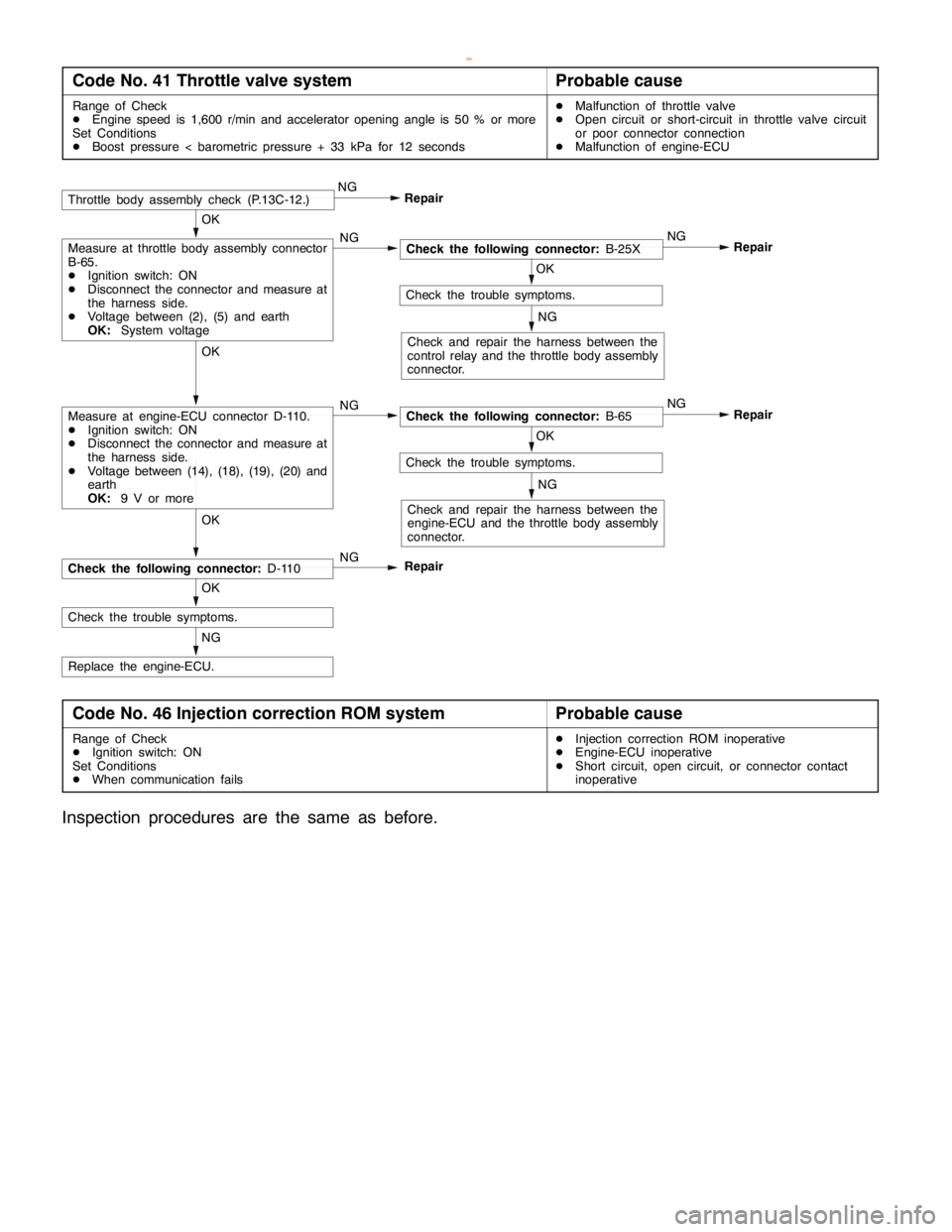
DIESEL FUEL <4M4> -Troubleshooting13C-6
Code No. 41 Throttle valve systemProbable cause
Range of Check
DEngine speed is 1,600 r/min and accelerator opening angle is 50 % or more
Set Conditions
DBoost pressure < barometric pressure + 33 kPa for 12 secondsDMalfunction of throttle valve
DOpen circuit or short-circuit in throttle valve circuit
or poor connector connection
DMalfunction of engine-ECU
NG
Replace the engine-ECU.
OK
Check the trouble symptoms.
OK
NG
Check the following connector:D-110
OK
Check the trouble symptoms.
NG
Check and repair the harness between the
engine-ECU and the throttle body assembly
connector.
Repair NG
OK
Check the following connector:B-65 NG
OK
Check the trouble symptoms.
NG
Check and repair the harness between the
control relay and the throttle body assembly
connector.
Repair NG
OK
Check the following connector:B-25X NGMeasure at throttle body assembly connector
B-65.
DIgnition switch: ON
DDisconnect the connector and measure at
the harness side.
DVoltage between (2), (5) and earth
OK:System voltage
RepairThrottle body assembly check (P.13C-12.)NG
Measure at engine-ECU connector D-110.
DIgnition switch: ON
DDisconnect the connector and measure at
the harness side.
DVoltage between (14), (18), (19), (20) and
earth
OK:9 V or more
Repair
Code No. 46 Injection correction ROM systemProbable cause
Range of Check
DIgnition switch: ON
Set Conditions
DWhen communication failsDInjection correction ROM inoperative
DEngine-ECU inoperative
DShort circuit, open circuit, or connector contact
inoperative
Inspection procedures are the same as before.
www.WorkshopManuals.co.uk
Purchased from www.WorkshopManuals.co.uk
Page 612 of 1839

DIESEL FUEL <4D5-stepIII>-General/General Information13E-2
GENERAL
OUTLINE OF CHANGE
An electronically-controlled injection pump has been added in order to comply with Regulation STEP
III. Due to this, the following service procedures have been added.
GENERAL INFORMATION
The electronically-controlled fuel injection system consists of sensors which detect the condition of the
diesel engine, an engine-ECU which controls the system based on signals from these sensors, and actuators
which operate according to control commands from the engine-ECU.
The engine-ECU carries out operations such as fuel injection rate control, fuel injection timing control
and idle up control. In addition, the engine-ECU is equipped with several self-diagnosis functions which
make troubleshooting easier in the event that a problem develops.
FUEL INJECTION RATE CONTROL
The fuel injection completion timing is controlled by means of a solenoid-type spill valve to ensure that
the optimum amount of fuel is supplied to the engine in accordance with gradual changes in the engine
running condition.
Before fuel injection starts, the solenoid-type spill valve is on (energized), so that the valve is closed.
As the plunger turns and rises, fuel is sent out under pressure, and when the fuel flow rate reaches
the target value for fuel injection, the solenoid-type spill valve turns off. When the solenoid-type spill
valve turns off, the fuel under high pressure inside the plunger is leaked out into the pump chamber
and fuel injection is completed.
FUEL INJECTION TIMING CONTROL
The position of the injection pump timer piston is controlled so that fuel injection is carried out at the
optimum timing in accordance with the engine running condition.
The timer piston position is determined by duty control of the timing control solenoid valve which is located
in the line between the high-pressure chamber and the low-pressure chamber of the timer piston.
The fuel injection timing is advanced by increasing the control duty of the timing control solenoid valve.
IDLE SPEED CONTROL
Controlling the fuel injection rate in accordance with the engine running condition maintains the idle speed
at the optimum condition.
SELF-DIAGNOSIS FUNCTION
DWhen an abnormality is detected in any of the sensors or actuators, the engine warning lamp illuminates
to warn the driver.
DWhen an abnormality is detected in any of the sensors or actuators, a diagnosis code number
corresponding to the problem which occurred is output.
DThe RAM data relating to the sensors and actuators which is stored in the engine-ECU can be read
using the MUT-II. In addition, the actuators can be force-driven under certain conditions.
OTHER CONTROL FUNCTIONS
1. Power Supply Control
When the ignition switch is turned to ON, the relay turns on and power is supplied to components
such as the timing control solenoid valve.
2. Intake Air Throttle Control
When the engine-ECU detects an abnormality in any of the sensors or actuators, the throttle valve
is half opened to restrict the amount of intake air in order to prevent the vehicle from running away.
3. A/C Relay Control
Turns the compressor clutch of the A/C ON and OFF
4. Condenser Fan Motor Relay Control
Controls the condenser fan motor relay based on the A/C switch, engine coolant temperature and
vehicle speed input signals.
5. Glow Control
Refer to GROUP 16.
6. EGR Control
Refer to GROUP 17.
www.WorkshopManuals.co.uk
Purchased from www.WorkshopManuals.co.uk
Page 614 of 1839

DIESEL FUEL <4D5-stepIII>-Service Specifications/Sealant13E-4
SERVICE SPECIFICATIONS
ItemStandard value
Fuel injection initial pressure kPa14,710 - 15,490
Accelerator pedal position sensor reference voltage V0.985 - 1.085
Accelerator pedal position sensor resistance kΩ3.5 - 6.5
Boost air temperature sensor (Intake air temperature
)itkΩ
When the temperature is 20_C2.3 - 3.0p(p
sensor) resistance kΩWhen the temperature is 80_C0.30 - 0.42
Engine coolant temperature sensor resistance kΩWhen the temperature is 20_C2.1 - 2.7gp
When the temperature is 80_C0.26 - 0.36
Fuel cut solenoid valve resistanceΩ6.8 - 9.2
Timing control valve resistanceΩ10.8 - 11.2
Timer piston position sensor resistanceΩConnector terminals No. 1 - No. 2160 - 168pp
Connector terminals No. 1 - No. 380 - 84
Connector terminals No. 2 - No. 380 - 84
Control sleeve position sensor resistanceΩConnector terminals No. 4 - No. 1211.2 - 12.4p
Connector terminals No. 4 - No. 85.6 - 6.2
Connector terminals No. 8 - No. 125.6 - 6.2
GE actuator (electronic governor) resistanceΩConnector terminals No. 6 - No. 100.64 - 0.72
Fuel temperature sensor resistance kΩConnector terminals No. 7 - No. 111.4 - 2.6
Pump speed sensor resistance kΩ1.36 - 1.84
Throttle solenoid valve resistanceΩ36 - 44
SEALANT
ItemSpecified sealant
Engine coolant temperature sensor3M Nut Locking Part No. 4171 or equivalent
www.WorkshopManuals.co.uk
Purchased from www.WorkshopManuals.co.uk
Page 617 of 1839

DIESEL FUEL <4D5-stepIII>-Troubleshooting13E-7
FAIL-SAFE, BACKUP FUNCTIONS
When abnormalities in the major sensors are detected by diagnosis functions, pre-set control logic operates
to maintain a safe driving condition for the vehicle.
Diagnosis itemControl features in malfunction
Accelerator pedal position sensorDAccelerator pedal released (idle switch ON)
Acceleration opening degree = 0 %
DAccelerator pedal applied (idle switch OFF)
Engine controlled at low speed
Acceleration opening degree = 30 % fixed
DVoid EGR control
Idle switchVoid idling speed control.
Engine speed sensorDEngine controlled at low speed
DVoid EGR control
DVoid variable geometry turbocharger control
Boost air temperature sensorDMaintain the intake air temperature at 50_C.
DVoid EGR control
Vehicle speed sensorDVoid idling speed control.
DVoid EGR control
Engine coolant temperature sensorDMaintain the engine coolant temperature at 80_C (However, the system
assumes the coolant temperature as 0_C).
DVoid EGR control
Control sleeve position sensorDEngine controlled at low speed
DVoid EGR control
DVoid variable geometry turbocharger control
Timer piston position sensorDInjection timing stabilizing control
DVoid EGR control
Barometric pressure sensor (ECU
built-in)DKeep the barometric pressure at 101 kPa.
DVoid EGR control
DVoid variable geometry turbocharger control
Fuel temperature sensorMaintain the fuel temperature at 40_C.
Boost pressure sensorDKeep the boost pressure as barometric pressure (101 kPa).
DVoid EGR control
DVoid variable geometry turbocharger control
Injection volume adjusting ROMVoid correction.
GE actuatorDEngine controlled at low speed
DVoid EGR control
DVoid variable geometry turbocharger control
Over boostDVoid variable geometry turbocharger control
DEngine controlled at low fuel injection
Timing control valveDInjection timing stabilizing control
DVoid EGR control
EGR valve position sensorVoid EGR control
Variable geometry control pressure
sensorDVoid EGR control
DVoid variable geometry turbocharger control
www.WorkshopManuals.co.uk
Purchased from www.WorkshopManuals.co.uk
Page 618 of 1839

DIESEL FUEL <4D5-stepIII>-Troubleshooting13E-8
INSPECTION CHART FOR DIAGNOSIS CODES
Code No.Diagnosis itemReference
page
11Accelerator pedal position sensor (main) system13E-9
12*Boost pressure sensor system13E-10
13Barometric pressure sensor (ECU built-in) system13E-11
14Fuel temperature sensor system13E-11
15Engine coolant temperature sensor system13E-12
16Boost air temperature sensor system13E-12
17Vehicle speed sensor system13E-13
18Pump speed sensor system13E-14
21Crank angle sensor system13E-15
23Idle switch (accelerator pedal position sensor built-in) system13E-16
25*Timer piston position sensor system13E-17
26*Control sleeve position sensor system13E-18
27Accelerator pedal position sensor (sub) system13E-19
41*Throttle solenoid valve system13E-20
43Timing control valve system13E-21
46Injection volume adjusting ROM system13E-22
48*GE actuator (in the middle of control sleeve position sensor inoperative) system13E-23
49*Over boost (variable geometry control pressure sensor system malfunction)13E-24
51EGR valve position sensor system13E-25
52Variable geometry control pressure sensor system13E-26
54Immobilizer system13E-27
Caution
If the above-mentioned diagnosis code number with the asterisks can be displayed along with another
code number in parentheses simultaneously, check the other code number before replacing the
engine-ECU.
12 (41, 49), 26 (48), 25 (43), 41 (12, 49), 48 (26), 49 (12, 41)
www.WorkshopManuals.co.uk
Purchased from www.WorkshopManuals.co.uk
Page 620 of 1839
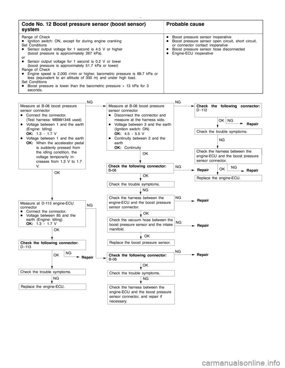
DIESEL FUEL <4D5-stepIII>-Troubleshooting13E-10
Code No. 12 Boost pressure sensor (boost sensor)
systemProbable cause
Range of Check
DIgnition switch: ON, except for during engine cranking
Set Conditions
DSensor output voltage for 1 second is 4.5 V or higher
(boost pressure is approximately 267 kPa).
or
DSensor output voltage for 1 second is 0.2 V or lower
(boost pressure is approximately 51.7 kPa or lower)
Range of Check
DEngine speed is 2,000 r/min or higher, barometric pressure is 69.7 kPa or
less (equivalent to an altitude of 300 m) and under high load.
Set Conditions
DBoost pressure is lower than the barometric pressure + 13 kPa for 3
seconds.DBoost pressure sensor inoperative
DBoost pressure sensor open circuit, short circuit,
or connector contact inoperative
DBoost pressure sensor hose disconnected
DEngine-ECU inoperative
NG
Check the trouble symptoms.
Replace the engine-ECU.
Check the following connector:
D-113
NGOK
NG
Repair
RepairOK
NG
Check the trouble symptoms.
OKOK
OK
Check the following connector:
B-08NG
Check the trouble symptoms. NG
Repair
NG
NG
Check the vacuum hose between the
boost pressure sensor and the intake
manifold.
Replace the boost pressure sensor.
OK OK OK
Repair
NG
Repair
Check the trouble symptoms.
Check the harness between the
engine-ECU and the boost pressure
sensor connector, and repair if
necessary.
NG OK
NG
RepairCheck the following connector:
B-08NG
Measure at B-08 boost pressure
sensor connector
DConnect the connector.
(Test harness: MB991348 used)
DVoltage between 1 and the earth
(Engine: Idling)
OK:1.3 - 1.7 V
DVoltage between 1 and the earth
OK:When the accelerator pedal
is suddenly pressed from
the idling condition, the
voltage temporarily in-
creases from 1.3 V to 1.7
V.
Measure at D-113 engine-ECU
connector
DConnect the connector.
DVoltage between 85 and the
earth (Engine: Idling)
OK:1.3 - 1.7 V
Check the harness between the
engine-ECU and the boost pressure
sensor connector.
Measure at B-08 boost pressure
sensor connector
DDisconnect the connector and
measure at the harness side.
DVoltage between 3 and the earth
(Ignition switch: ON)
OK:4.5 - 5.5 V
DContinuity between 2 and the
earth
OK:Continuity
Replace the engine-ECU.NGCheck the harness between the
engine-ECU and the boost pressure
sensor connector.
Replace the engine-ECU.OK
NG
Repair
Check the following connector:
D-112
www.WorkshopManuals.co.uk
Purchased from www.WorkshopManuals.co.uk
Page 621 of 1839
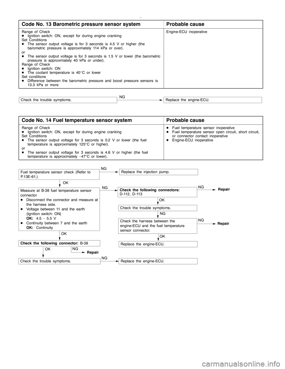
DIESEL FUEL <4D5-stepIII>-Troubleshooting13E-11
Code No. 13 Barometric pressure sensor systemProbable cause
Range of Check
DIgnition switch: ON, except for during engine cranking
Set Conditions
DThe sensor output voltage is for 3 seconds is 4.5 V or higher (the
barometric pressure is approximately 114 kPa or over).
or
DThe sensor output voltage is for 3 seconds is 1.5 V or lower (the barometric
pressure is approximately 40 kPa or under).
Range of Check
DIgnition switch: ON
DThe coolant temperature is 40_C or lower
Set conditions
DDifference between the barometric pressure and boost pressure sensors is
13.3 kPa or moreEngine-ECU inoperative
Replace the engine-ECU.NGCheck the trouble symptoms.
Code No. 14 Fuel temperature sensor systemProbable cause
Range of Check
DIgnition switch: ON, except for during engine cranking
Set Conditions
DThe sensor output voltage for 3 seconds is 0.2 V or lower (the fuel
temperature is approximately 125°C or higher).
or
DThe sensor output voltage for 3 seconds is 4.6 V or higher (the fuel
temperature is approximately - 47°C or lower).DFuel temperature sensor inoperative
DFuel temperature sensor open circuit, short circuit,
or connector contact inoperative
DEngine-ECU inoperative
OK
Measure at B-38 fuel temperature sensor
connector
DDisconnect the connector and measure at
the harness side.
DVoltage between 11 and the earth
(Ignition switch: ON)
OK:4.5 - 5.5 V
DContinuity between 7 and the earth
OK:ContinuityNGCheck the following connectors:
D-112, D-113NG
Repair
OK
OK
Check the harness between the
engine-ECU and the fuel temperature
sensor connector.Repair
NG
Check the trouble symptoms.
Replace the engine-ECU.NG
Replace the engine-ECU.OKNG
Replace the injection pump.
OK
Repair
Check the following connector:B-38
NG
NGCheck the trouble symptoms.
Fuel temperature sensor check (Refer to
P.13E-61.)
www.WorkshopManuals.co.uk
Purchased from www.WorkshopManuals.co.uk