fuel pressure MITSUBISHI MONTERO 2000 Service Manual PDF
[x] Cancel search | Manufacturer: MITSUBISHI, Model Year: 2000, Model line: MONTERO, Model: MITSUBISHI MONTERO 2000Pages: 1839, PDF Size: 29.19 MB
Page 498 of 1839

DIESEL FUEL <4M4> -Troubleshooting13C-7
INSPECTION CHART FOR DIAGNOSIS CODES
Code No.Diagnosis itemReference
page
11Accelerator pedal position sensor (main) system13C-8
12*Boost pressure sensor system13C-9
13Barometric pressure sensor (ECU built-in) system13C-10
14Fuel temperature sensor system13C-10
15Engine coolant temperature sensor system13C-11
16Boost air temperature sensor system13C-11
17Vehicle speed sensor system13C-12
18Engine speed sensor (backup) system13C-13
21Engine speed sensor system13C-14
23Idle switch (accelerator pedal position sensor built-in) system13C-15
25*Timer piston position sensor system13C-16
26*Control sleeve position sensor system13C-17
27Accelerator pedal position sensor (sub) system13C-18
41*Main throttle solenoid valve system13C-19
43Timing control valve system13C-20
46Injection correction ROM system13C-21
48*GE actuator (in the middle of control sleeve position sensor inoperative) system13C-21
49*Over boost (turbocharger waste gate malfunction)13C-22
54Immobilizer system13C-22
Caution
If the the above-mentioned diagnosis code number with the asterisks can be displayed along with
another code number in parentheses simultaneously, check the other code number before replacing
the engine-ECU.
12 (41, 49), 26 (48), 25 (43), 41 (12, 49), 48 (26), 49 (12, 41)
www.WorkshopManuals.co.uk
Purchased from www.WorkshopManuals.co.uk
Page 500 of 1839
DIESEL FUEL <4M4> -Troubleshooting13C-9
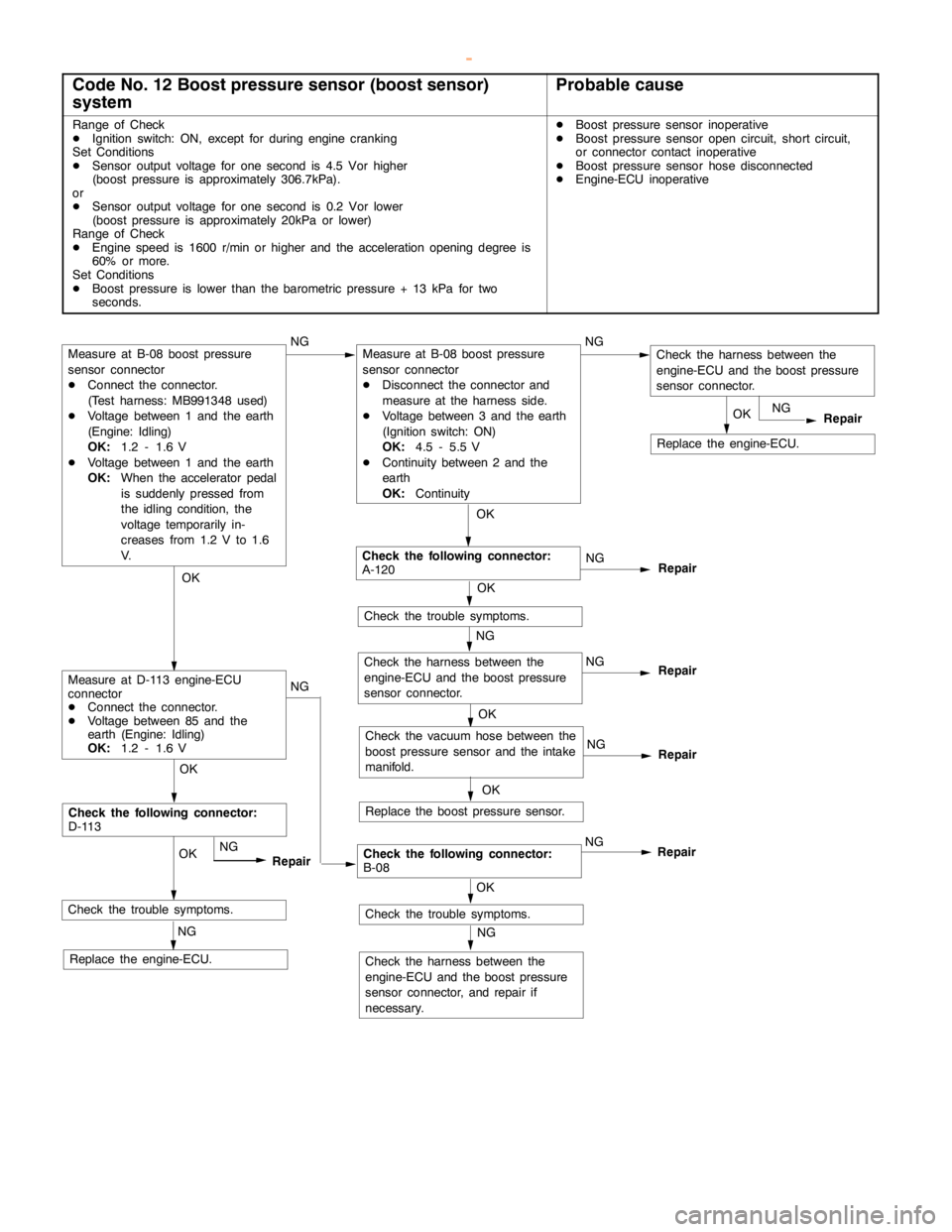
Code No. 12 Boost pressure sensor (boost sensor)
systemProbable cause
Range of Check
DIgnition switch: ON, except for duringenginecranking
Set Conditions
DSensor output voltage for one second is 4.5 Vor higher
(boost pressure is approximately 306.7kPa).
or
DSensor output voltage for one second is 0.2 Vor lower
(boost pressure is approximately 20kPa or lower)
Range of Check
DEngine speed is 1600 r/min or higher and the accelerationopening degree is
60% or more.
Set Conditions
DBoost pressure is lower than the barometric pressure + 13 kPa for two
seconds.DBoost pressure sensor inoperative
DBoost pressure sensoropencircuit, short circuit,
or connector contact inoperative
DBoost pressure sensor hose disconnected
DEngine-ECU inoperative
Check the harness between the
engine-ECU and the boost pressure
sensor connector.
NG
Check the trouble symptoms.
Replace the engine-ECU.
Check the following connector:
D-113
NGOK
NG
Repair
RepairOK
NG
Replace the engine-ECU.
OKOK
OK
Check the following connector:
A-120NG
Check the trouble symptoms. NG
Repair
NG
NG
Check the vacuum hose between the
boost pressure sensor and the intake
manifold.
Replace the boost pressure sensor.
OK OK OK
Repair
NG
Repair
Check the trouble symptoms.
Check the harness between the
engine-ECU and the boost pressure
sensor connector, and repair if
necessary.
NG OK
NG
RepairCheck the following connector:
B-08NG
Measure at B-08 boost pressure
sensor connector
DConnect the connector.
(Test harness: MB991348 used)
DVoltage between 1 and the earth
(Engine: Idling)
OK:
1.2 - 1.6 V
DVoltage between 1 and the earth
OK:
When the accelerator pedal
is suddenly pressed from
the idling condition, the
voltage temporarily in-
creases from 1.2 V to 1.6
V.
Measure at D-113 engine-ECU
connector
DConnect the connector.
DVoltage between 85 and the
earth (Engine: Idling)
OK:
1.2 - 1.6 V
Check the harness between the
engine-ECU and the boost pressure
sensor connector.
Measure at B-08 boost pressure
sensor connector
DDisconnect the connector and
measure at the harness side.
DVoltage between 3 and the earth
(Ignition switch: ON)
OK:
4.5 - 5.5 V
DContinuity between 2 and the
earth
OK:
Continuity
www.WorkshopManuals.co.uk
Purchased from www.WorkshopManuals.co.uk
Page 501 of 1839
DIESEL FUEL <4M4> -Troubleshooting13C-10
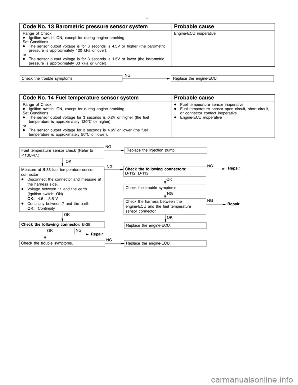
Code No. 13 Barometric pressure sensor systemProbable cause
Range of Check
DIgnition switch: ON, except for duringenginecranking
Set Conditions
DThe sensor output voltage is for 3 seconds is 4.5V or higher (the barometric
pressure is approximately 120 kPa or over).
or
DThe sensor output voltage is for 3 seconds is 1.5V or lower (the barometric
pressure is approximately 33 kPa or under).Engine-ECU inoperative
Replace the engine-ECU.NGCheck the trouble symptoms.
Code No. 14 Fuel temperature sensor systemProbable cause
Range of Check
DIgnition switch: ON, except for duringenginecranking
Set Conditions
DThe sensor output voltage for 3 seconds is 0.2V or higher (the fuel
temperature is approximately 120°C or higher).
or
DThe sensor output voltage for 3 seconds is 4.6V or lower (the fuel
temperature is approximately 50°C or lower).DFuel temperature sensor inoperative
DFuel temperature sensoropencircuit, short circuit,
or connector contact inoperative
DEngine-ECU inoperative
OK
Measure at B-38 fuel temperature sensor
connector
DDisconnect the connector and measure at
the harness side.
DVoltage between 11 and the earth
(Ignition switch: ON)
OK:
4.5 - 5.5 V
DContinuity between 7 and the earth
OK:
ContinuityNGCheck the following connectors:
D-112, D-113NG
Repair
OK
OK
Check the harness between the
engine-ECU and the fuel temperature
sensor connector.Repair
NG
Check the trouble symptoms.
Replace the engine-ECU.NG
Replace the engine-ECU.OKNG
Replace the injection pump.
OK
Repair
Check the following connector:
B-38
NG
NGCheck the trouble symptoms.
Fuel temperature sensor check (Refer to
P.13C-47.)
www.WorkshopManuals.co.uk
Purchased from www.WorkshopManuals.co.uk
Page 510 of 1839
DIESEL FUEL <4M4> -Troubleshooting13C-19
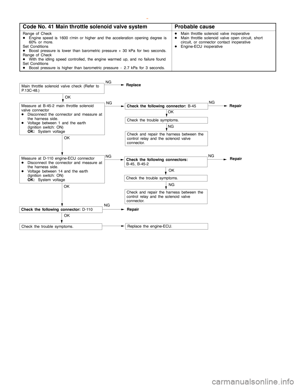
Code No. 41 Main throttle solenoid valve systemProbable cause
Range of Check
DEngine speed is 1600 r/min or higher and the accelerationopening degree is
60% or more.
Set Conditions
DBoost pressure is lower than barometric pressure + 30 kPa for two seconds.
Range of Check
DWith the idlingspeed controlled, theengine warmed up, and no failure found
Set Conditions
DBoost pressure is higher than barometric pressure - 2.7 kPa for 3 seconds.DMain throttle solenoidvalve inoperative
DMain throttle solenoidvalveopencircuit, short
circuit, or connector contact inoperative
DEngine-ECU inoperative
OK
Check the following connector:
B-45NG
Repair
OK
OK
Check and repair the harness between the
control relay and the solenoid valve
connector.
Main throttle solenoidvalve check (Refer to
P.13C-48.)
Check the trouble symptoms.
Replace the engine-ECU.
NG
OK
RepairCheck the following connector:
D-110
Check the trouble symptoms.NGReplace
NG NG
Check the following connectors:
B-45, B-45-2NG
Repair
OK
Check and repair the harness between the
control relay and the solenoid valve
connector.
Check the trouble symptoms.
NG
NGMeasure at D-110 engine-ECU connector
DDisconnect the connector and measure at
the harness side.
DVoltage between 14 and the earth
(Ignition switch: ON)
OK:
System voltageOK
Measure at B-45-2 main throttle solenoid
valve connector
DDisconnect the connector and measure at
the harness side.
DVoltage between 1 and the earth
(Ignition switch: ON)
OK:
System voltage
www.WorkshopManuals.co.uk
Purchased from www.WorkshopManuals.co.uk
Page 513 of 1839
DIESEL FUEL <4M4> -TroubleshootingDIESEL FUEL <4M4> -Troubleshooting13C-22
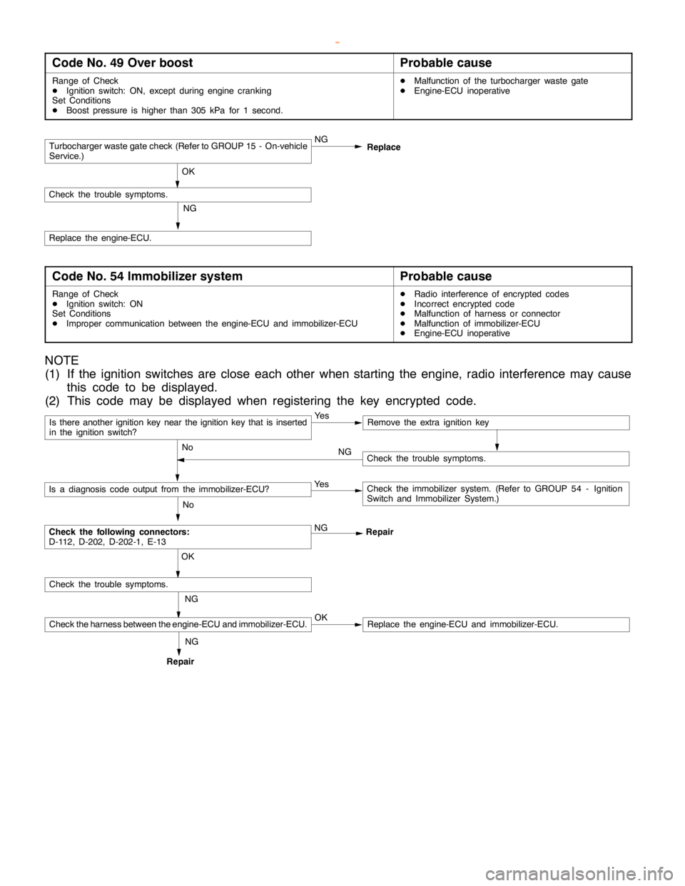
Code No. 49 Over boostProbable cause
Range of Check
DIgnition switch: ON, except duringenginecranking
Set Conditions
DBoost pressure is higher than 305 kPa for 1 second.DMalfunction of the turbocharger waste gate
DEngine-ECU inoperative
Turbocharger waste gate check (Refer to GROUP 15 - On-vehicle
Service.)NG
OK
Check the trouble symptoms.
NG
Replace the engine-ECU.Replace
Code No. 54 Immobilizer systemProbable cause
Range of Check
DIgnition switch: ON
Set Conditions
DImproper communication between the engine-ECU and immobilizer-ECUDRadio interference of encrypted codes
DIncorrect encrypted code
DMalfunction of harness or connector
DMalfunction of immobilizer-ECU
DEngine-ECU inoperative
NOTE
(1) If the ignition switches are close each other when starting the engine, radio interference may cause
this code to be displayed.
(2) This code may be displayed when registering the key encrypted code.
Is there another ignition key near the ignition key that is inserted
in the ignition switch?Ye sRemove the extra ignition key
No
Check the following connectors:
D-112, D-202, D-202-1, E-13NG
Repair
No
Is a diagnosis code output from the immobilizer-ECU?Ye sCheck the immobilizer system. (Refer to GROUP 54 - Ignition
Switch and Immobilizer System.)
NG OK
Check the trouble symptoms.
Check the harness between the engine-ECU and immobilizer-ECU.OKReplace the engine-ECU and immobilizer-ECU.
Check the trouble symptoms. NG
RepairNG
www.WorkshopManuals.co.uk
Purchased from www.WorkshopManuals.co.uk
Page 517 of 1839
DIESEL FUEL <4M4> -Troubleshooting13C-26
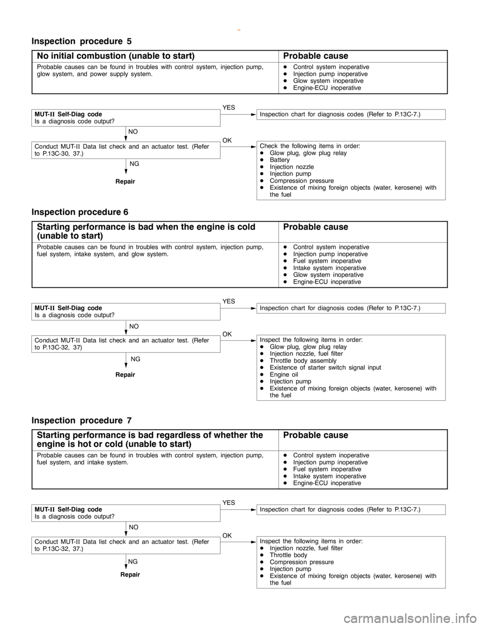
Inspection procedure 5
No initial combustion (unable to start)
Probable cause
Probable causes can be found in troubles with control system, injectionpump,
glow system, and power supply system.DControl system inoperative
DInjection pump inoperative
DGlow system inoperative
DEngine-ECU inoperative
NG
Repair
MUT-
IISelf-Diag code
Is a diagnosis code output?YESInspection chart for diagnosis codes (Refer to P.13C-7.)
NO
Conduct MUT-IIData list check and an actuator test. (Refer
to P.13C-30, 37.)OKCheck the following items in order:
DGlow plug, glowplugrelay
DBattery
DInjection nozzle
DInjection pump
DCompression pressure
DExistence of mixing foreign objects (water, kerosene) with
the fuel
Inspection procedure 6
Starting performance is bad when the engine is cold
(unable to start)
Probable cause
Probable causes can be found in troubles with control system, injectionpump,
fuel system, intake system, and glow system.DControl system inoperative
DInjection pump inoperative
DFuel system inoperative
DIntake system inoperative
DGlow system inoperative
DEngine-ECU inoperative
NG
Repair
MUT-
IISelf-Diag code
Is a diagnosis code output?YESInspection chart for diagnosis codes (Refer to P.13C-7.)
NO
Conduct MUT-IIData list check and an actuator test. (Refer
to P.13C-32, 37)OKInspect the following items in order:
DGlow plug, glowplugrelay
DInjection nozzle, fuel filter
DThrottle body assembly
DExistence of starter switch signal input
DEngine oil
DInjection pump
DExistence of mixing foreign objects (water, kerosene) with
the fuel
Inspection procedure 7
Starting performance is bad regardless of whether the
engine is hot or cold (unable to start)
Probable cause
Probable causes can be found in troubles with control system, injectionpump,
fuel system, and intake system.DControl system inoperative
DInjection pump inoperative
DFuel system inoperative
DIntake system inoperative
DEngine-ECU inoperative
NG
Repair
MUT-
IISelf-Diag code
Is a diagnosis code output?YESInspection chart for diagnosis codes (Refer to P.13C-7.)
NO
Conduct MUT-IIData list check and an actuator test. (Refer
to P.13C-32, 37.)OKInspect the following items in order:
DInjection nozzle, fuel filter
DThrottle body
DCompression pressure
DInjection pump
DExistence of mixing foreign objects (water, kerosene) with
the fuel
www.WorkshopManuals.co.uk
Purchased from www.WorkshopManuals.co.uk
Page 519 of 1839
DIESEL FUEL <4M4> -Troubleshooting13C-28
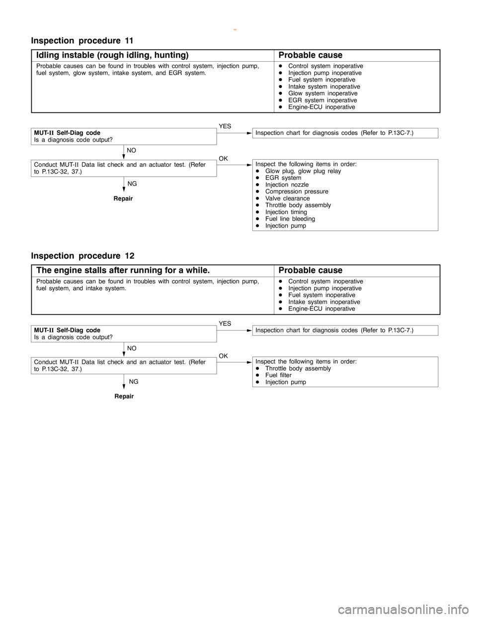
Inspection procedure 11
Idling instable (rough idling, hunting)
Probable cause
Probable causes can be found in troubles with control system, injectionpump,
fuel system, glow system, intake system, and EGR system.DControl system inoperative
DInjection pump inoperative
DFuel system inoperative
DIntake system inoperative
DGlow system inoperative
DEGR system inoperative
DEngine-ECU inoperative
NG
Repair
MUT-
IISelf-Diag code
Is a diagnosis code output?YESInspection chart for diagnosis codes (Refer to P.13C-7.)
NO
Conduct MUT-IIData list check and an actuator test. (Refer
to P.13C-32, 37.)OKInspect the following items in order:
DGlow plug, glowplugrelay
DEGR system
DInjection nozzle
DCompression pressure
DValve clearance
DThrottle body assembly
DInjection timing
DFuel line bleeding
DInjection pump
Inspection procedure 12
The engine stalls after running for a while.
Probable cause
Probable causes can be found in troubles with control system, injectionpump,
fuel system, and intake system.DControl system inoperative
DInjection pump inoperative
DFuel system inoperative
DIntake system inoperative
DEngine-ECU inoperative
NG
Repair
MUT-
IISelf-Diag code
Is a diagnosis code output?YESInspection chart for diagnosis codes (Refer to P.13C-7.)
NO
Conduct MUT-IIData list check and an actuator test. (Refer
to P.13C-32, 37.)OKInspect the following items in order:
DThrottle body assembly
DFuel filter
DInjection pump
www.WorkshopManuals.co.uk
Purchased from www.WorkshopManuals.co.uk
Page 520 of 1839
DIESEL FUEL <4M4> -Troubleshooting13C-29
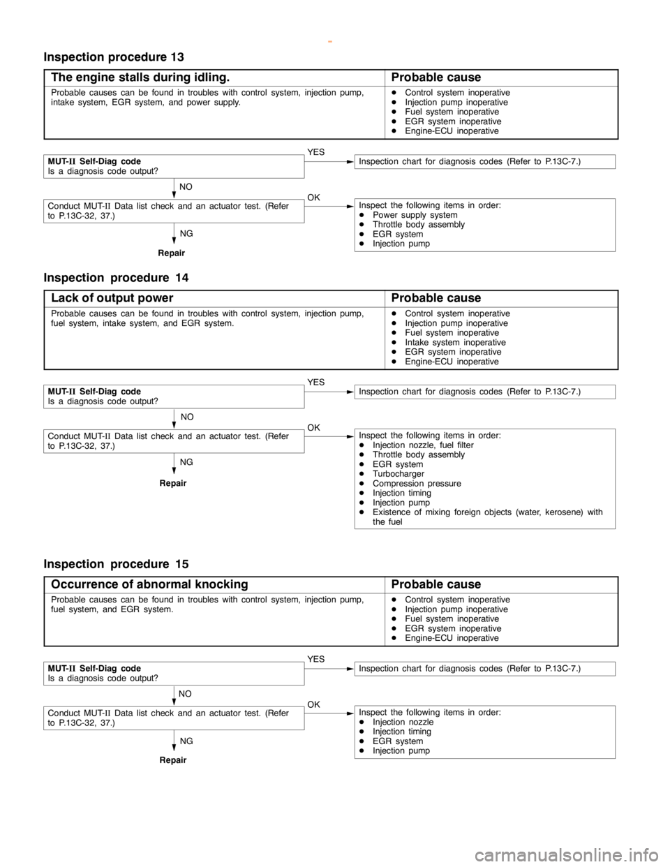
Inspection procedure 13
The engine stalls during idling.
Probable cause
Probable causes can be found in troubles with control system, injectionpump,
intake system, EGR system, and power supply.DControl system inoperative
DInjection pump inoperative
DFuel system inoperative
DEGR system inoperative
DEngine-ECU inoperative
NG
Repair
MUT-
IISelf-Diag code
Is a diagnosis code output?YESInspection chart for diagnosis codes (Refer to P.13C-7.)
NO
Conduct MUT-IIData list check and an actuator test. (Refer
to P.13C-32, 37.)OKInspect the following items in order:
DPower supply system
DThrottle body assembly
DEGR system
DInjection pump
Inspection procedure 14
Lack of output power
Probable cause
Probable causes can be found in troubles with control system, injectionpump,
fuel system, intake system, and EGR system.DControl system inoperative
DInjection pump inoperative
DFuel system inoperative
DIntake system inoperative
DEGR system inoperative
DEngine-ECU inoperative
NG
Repair
MUT-
IISelf-Diag code
Is a diagnosis code output?YESInspection chart for diagnosis codes (Refer to P.13C-7.)
NO
Conduct MUT-IIData list check and an actuator test. (Refer
to P.13C-32, 37.)OKInspect the following items in order:
DInjection nozzle, fuel filter
DThrottle body assembly
DEGR system
DTurbocharger
DCompression pressure
DInjection timing
DInjection pump
DExistence of mixing foreign objects (water, kerosene) with
the fuel
Inspection procedure 15
Occurrence of abnormal knocking
Probable cause
Probable causes can be found in troubles with control system, injectionpump,
fuel system, and EGR system.DControl system inoperative
DInjection pump inoperative
DFuel system inoperative
DEGR system inoperative
DEngine-ECU inoperative
NG
Repair
MUT-
IISelf-Diag code
Is a diagnosis code output?YESInspection chart for diagnosis codes (Refer to P.13C-7.)
NO
Conduct MUT-IIData list check and an actuator test. (Refer
to P.13C-32, 37.)OKInspect the following items in order:
DInjection nozzle
DInjection timing
DEGR system
DInjection pump
www.WorkshopManuals.co.uk
Purchased from www.WorkshopManuals.co.uk
Page 523 of 1839

DIESEL FUEL <4M4> -Troubleshooting13C-32
DATA LIST REFERENCE TABLE
Item
No.Check itemInspection conditionsValue to be
determined
as normalCode No.
or inspec-
tion proce-
dure No.Reference
page
01Boost air
temperatureIgnition switch: ON or
the engine runningWhen the intake air
temperature is - 20_C-20_CCode No.
1613C-11
sensorWhen the intake air
temperature is 0_C0_C
When the intake air
temperature is 20_C20_C
When the intake air
temperature is 40_C40_C
When the intake air
temperature is 80_C80_C
02Engine cool-
ant temper-
ature sensorIgnition switch: ON or
the engine runningWhen the engine cool-
ant temperature is
-20_C-20_CCode No.
1513C-11
When the engine cool-
ant temperature is
0_C0_C
When the engine cool-
ant temperature is
20_C20_C
When the engine cool-
ant temperature is
40_C40_C
When the engine cool-
ant temperature is
80_C80_C
03BarometricIgnition switch: ONAltitude 0 m101 kPaCode No.13C-10
pressureAltitude 600 m95 kPa13
sensorAltitude 1,200 m88 kPa
Altitude 1,800 m81 kPa
04Boost pres-DEngine coolantAltitude 0 m101 kPaCode No.13C-9
sure sensortemperature:Altitude 600 m95 kPa12
80 - 95_C
DLamps, electricalAltitude 1,200 m88 kPa
cooling fan, andAltitude 1,800 m81 kPaaccessories: OFF
DTransmission: PIdling81 - 109 kPaDTransmission: P
range
DIgnition switch: ON
When sudden racing is
doneIncreased
05Fuel tem-
peratureIgnition switch: ON or
the engine runningWhen the fuel temper-
ature is - 20_C-20_CCode No.
1413C-10
sensorWhen the fuel temper-
ature is 0_C0_C
When the fuel temper-
ature is 20_C20_C
When the fuel temper-
ature is 40_C40_C
When the fuel temper-
ature is 80_C80_C
www.WorkshopManuals.co.uk
Purchased from www.WorkshopManuals.co.uk
Page 531 of 1839

DIESEL FUEL <4M4> -Troubleshooting13C-40
Terminal
No.Normal condition: Inspection conditions (engine status) Check item
36Selector switch be-
tween A/T and M/TIgnition switch: ON0-1V
37Inhibitor switchIgnition switch: ON
(Engine stops)Set the selector lever to P
or N0-1V
Set the selector lever to D,
2, L, or RSystem voltage
39Stop lamp switchDepress the brake pedalSystem voltage
40Brake switchDepress the brake pedal0-1V
46Control relayIgnition switch: ON0-1V
Ignition switch: ON®OFF (in about 8 seconds)System voltage
51Engine speed sensor
(backup)Engine: Idling1.5 - 2.5 V
55Accelerator pedal posi-
tion sensor (sub)Ignition switch: ONAccelerator pedal: Idling
position0.9 - 1.1 V
Accelerator pedal: Fully
opened position4.1 V or higher
71Ignition switch-STEngine: Cranking8 V or higher
74Control sleeve positionIgnition switch: ON (Engine stops)2.2 - 2.7 V
73sensor2.0 - 4.0 V
752.0 - 4.0 V
76Timer piston positionIgnition switch: ON (Engine stops)2.2 - 2.7 V
77sensor2.0 - 4.0 V
782.0 - 4.0 V
80Back-up power supplyIgnition switch: OFFSystem voltage
82Ignition switch-IGIgnition switch: ONSystem voltage
83Engine coolant tem-
perature sensorIgnition switch: ONEngine coolant tempera-
ture: 0_C3.4 - 4.5 V
Engine coolant tempera-
ture: 20_C2.6 - 3.6 V
Engine coolant tempera-
ture: 40_C1.8 - 2.5 V
Engine coolant tempera-
ture: 80_C0.7 - 1.1 V
84Accelerator pedal posi-
tion sensor (main)Ignition switch: ONAccelerator pedal: Idling
position0.9 - 1.1 V
Accelerator pedal: Fully
opened position4.1 V or higher
85Boost pressure sensorIgnition switch: ON (760 mmHg)1.2 - 1.6 V
86Vehicle speed sensorDIgnition switch: ON
DMove the vehicle forward slowly0V«5 V (repeat the
change)
www.WorkshopManuals.co.uk
Purchased from www.WorkshopManuals.co.uk