MITSUBISHI MONTERO 2000 Service Repair Manual
Manufacturer: MITSUBISHI, Model Year: 2000, Model line: MONTERO, Model: MITSUBISHI MONTERO 2000Pages: 1839, PDF Size: 29.19 MB
Page 1221 of 1839
BASIC BRAKE SYSTEM -Troubleshooting35A-13
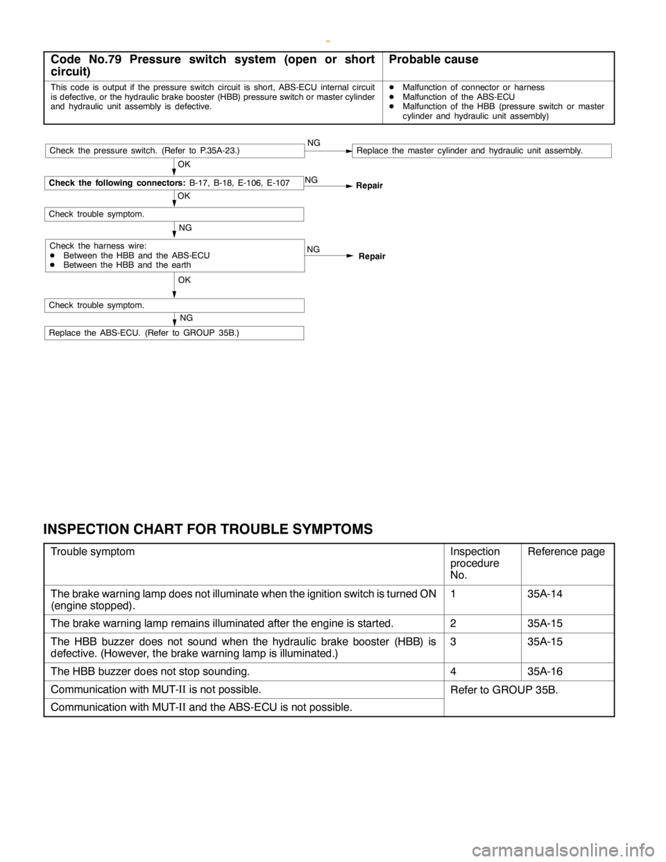
Code No.79 Pressure switch system (open or short
circuit)Probable cause
This code is output if the pressure switch circuit is short, ABS-ECU internal circuit
is defective, or the hydraulic brake booster (HBB) pressure switch or master cylinder
and hydraulic unit assembly is defective.DMalfunction of connector or harness
DMalfunction of the ABS-ECU
DMalfunction of the HBB (pressure switch or master
cylinder and hydraulic unit assembly)
NG
Repair
NG
OKRepair NG
OK
Check trouble symptom.
Check the following connectors:
B-17, B-18, E-106, E-107
Check the harness wire:
DBetween the HBB and the ABS-ECU
DBetween the HBB and the earthNG
Check trouble symptom.
Replace the ABS-ECU. (Refer to GROUP 35B.)
NG
OKCheck the pressure switch. (Refer to P.35A-23.)Replace the master cylinder and hydraulic unit assembly.
INSPECTION CHART FOR TROUBLE SYMPTOMS
Trouble symptomInspection
procedure
No.Reference page
The brake warning lamp does not illuminate when the ignition switch is turned ON
(engine stopped).135A-14
The brake warning lamp remains illuminated after the engine is started.235A-15
The HBB buzzer does not sound when the hydraulic brake booster (HBB) is
defective. (However, the brake warning lamp is illuminated.)335A-15
The HBB buzzer does not stop sounding.435A-16
Communication with MUT-II
is not possible.Refer to GROUP 35B.
Communication with MUT-II
and the ABS-ECU is not possible.
www.WorkshopManuals.co.uk
Purchased from www.WorkshopManuals.co.uk
Page 1222 of 1839
BASIC BRAKE SYSTEM -Troubleshooting35A-14
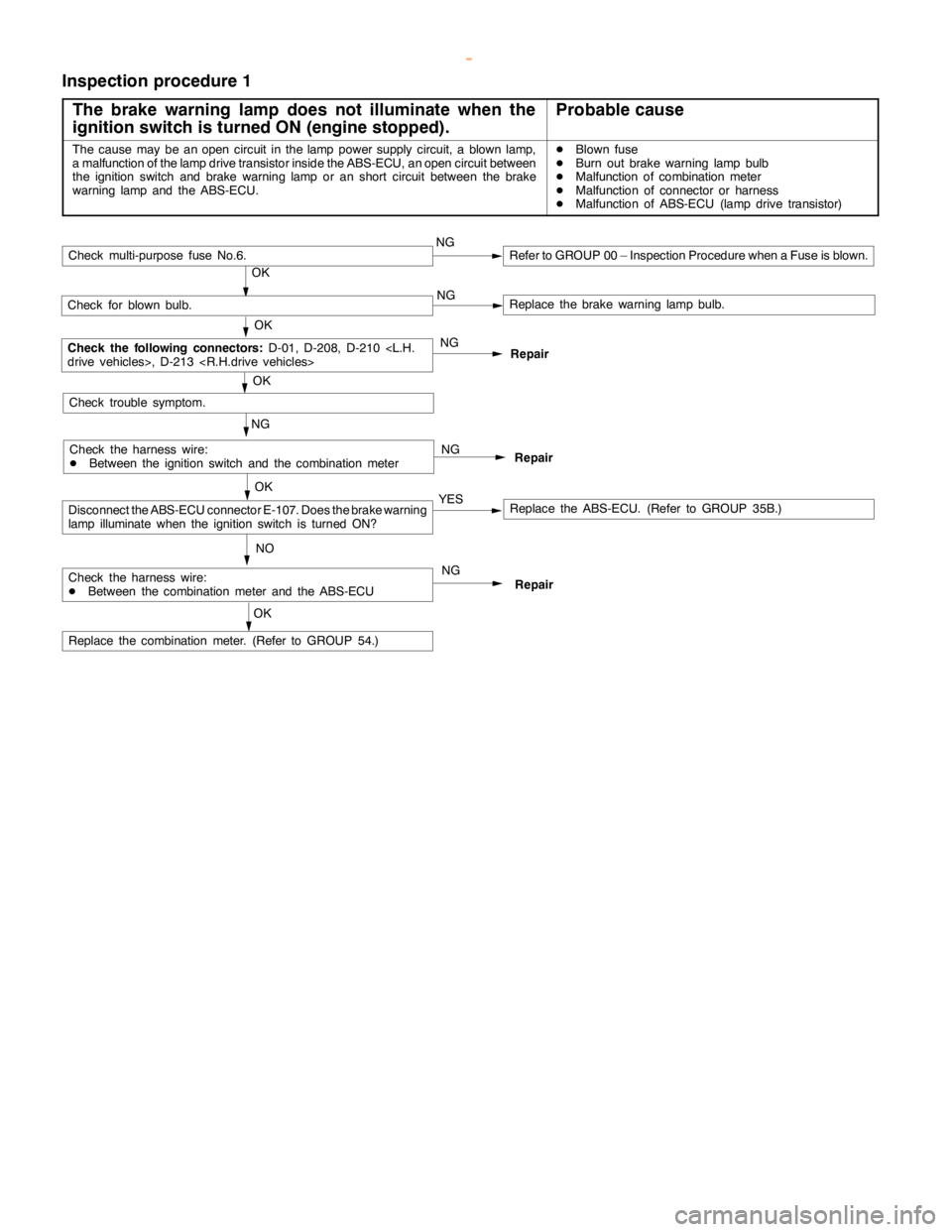
Inspection procedure 1
The brake warning lamp does not illuminate when the
ignition switch is turned ON (engine stopped).
Probable cause
The cause may be anopencircuit in thelamppower supply circuit, a blown lamp,
a malfunction of the lampdrive transistor inside the ABS-ECU, anopencircuit between
the ignition switch and brake warninglamp or anshort circuit between the brake
warning lamp and theABS-ECU.DBlown fuse
DBurn out brake warninglamp bulb
DMalfunction of combination meter
DMalfunction of connector or harness
DMalfunction of ABS-ECU (lamp drive transistor)
Repair NG NG
NO
Replace the ABS-ECU. (Refer to GROUP 35B.)
Repair
Repair
NG
OK
Check for blown bulb.Replace the brake warninglamp bulb.
OK
Check the following connectors:
D-01, D-208, D-210
NG
Replace the combination meter. (Refer to GROUP 54.)
OK
Check trouble symptom.
OK
YES
Check multi-purpose fuse No.6.NGRefer to GROUP 00 – Inspection Procedure when a Fuse is blown.
Check the harness wire:
DBetween the ignition switch and the combination meter
Check the harness wire:
DBetween the combination meter and the ABS-ECU
Disconnect the ABS-ECU connector E-107. Does the brake warning
lamp illuminatewhen the ignition switch is turned ON?
NG
OK
www.WorkshopManuals.co.uk
Purchased from www.WorkshopManuals.co.uk
Page 1223 of 1839
BASIC BRAKE SYSTEM -Troubleshooting35A-15
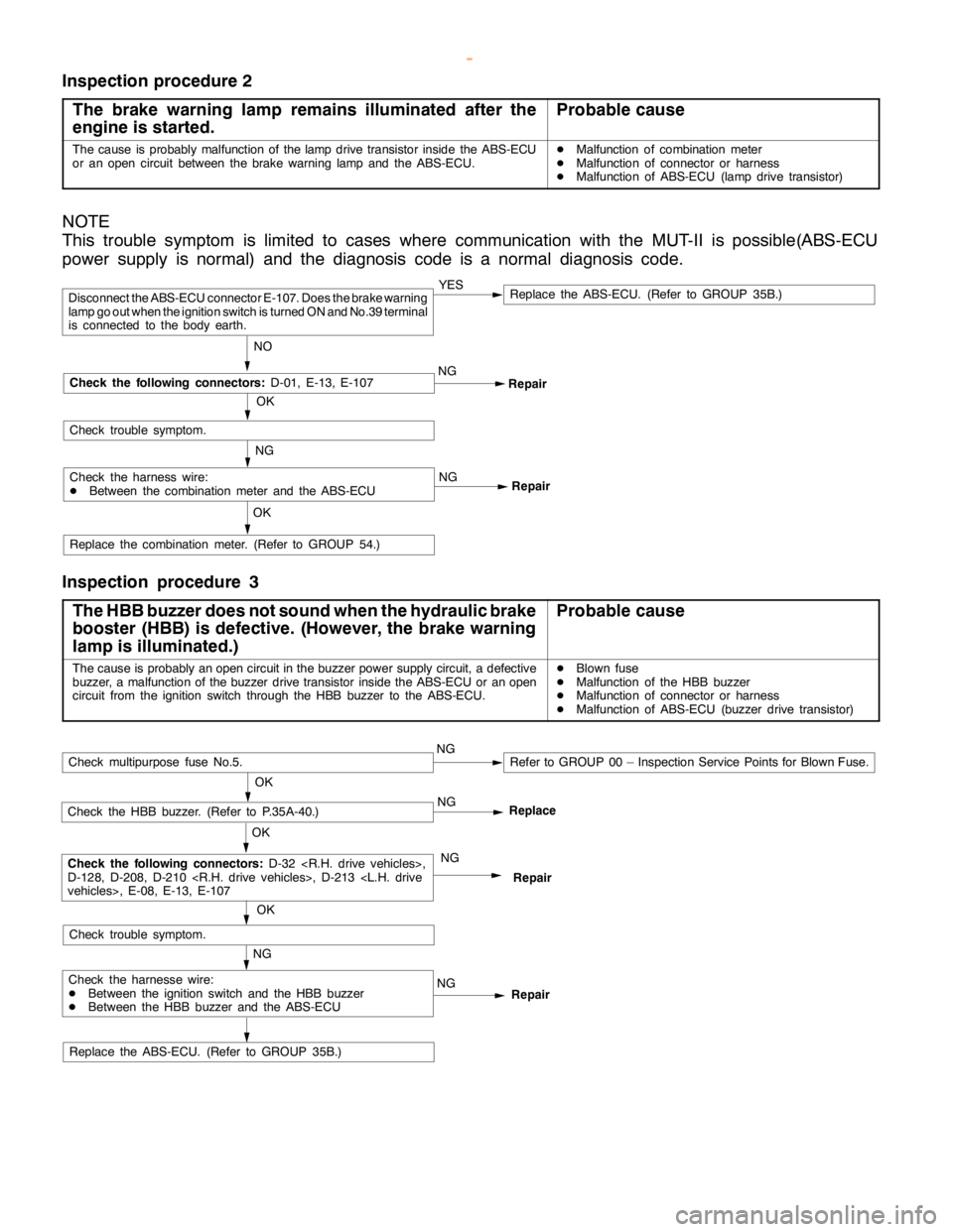
Inspection procedure 2
The brake warning lamp remains illuminated after the
engine is started.
Probable cause
The cause is probably malfunction of thelampdrive transistor inside the ABS-ECU
or an opencircuit between the brake warninglamp and theABS-ECU.DMalfunction of combination meter
DMalfunction of connector or harness
DMalfunction of ABS-ECU (lamp drive transistor)
NOTE
This trouble symptom is limited to cases where communication with the MUT-II is possible(ABS-ECU
power supply is normal) and the diagnosis code is a normal diagnosis code.
Repair NG
Repair
Replace the combination meter. (Refer to GROUP 54.)
OK
YESReplace the ABS-ECU. (Refer to GROUP 35B.)
NO
Disconnect the ABS-ECU connector E-107. Does the brake warning
lamp go outwhen the ignition switch is turned ON and No.39 terminal
is connected to the body earth.
OK
Check the following connectors:
D-01, E-13, E-107
Check trouble symptom.
Check the harness wire:
DBetween the combination meter and the ABS-ECUNG
NG
Inspection procedure 3
The HBB buzzer does not sound when the hydraulic brake
booster (HBB) is defective. (However, thebrake warning
lamp is illuminated.)
Probable cause
The cause is probably anopencircuit in the buzzer power supply circuit, a defective
buzzer, a malfunction of the buzzer drive transistor inside the ABS-ECU or anopen
circuit from the ignition switch through the HBB buzzer to the ABS-ECU.DBlown fuse
DMalfunction of the HBB buzzer
DMalfunction of connector or harness
DMalfunction of ABS-ECU (buzzer drive transistor)
Replace the ABS-ECU. (Refer to GROUP 35B.)
Repair NG
Repair
NG
OK
Check the HBB buzzer. (Refer to P.35A-40.)
OK
Check the following connectors:
D-32
D-128, D-208, D-210
NG
OK
Check trouble symptom.
Check multipurpose fuse No.5.NGRefer to GROUP 00 – Inspection Service Points for Blown Fuse.
Check the harnesse wire:
DBetween the ignition switch and the HBB buzzer
DBetween the HBB buzzer and the ABS-ECUNGReplace
www.WorkshopManuals.co.uk
Purchased from www.WorkshopManuals.co.uk
Page 1224 of 1839
BASIC BRAKE SYSTEM -Troubleshooting35A-16
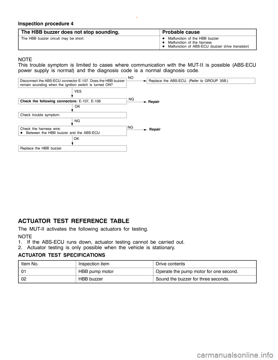
Inspection procedure 4
The HBB buzzer does not stop sounding.
Probable cause
The HBB buzzer circuit may be short.DMalfunction of the HBB buzzer
DMalfunction of the harness
DMalfunction of ABS-ECU (buzzer drive transistor)
NOTE
This trouble symptom is limited to cases where communication with the MUT-II
is possible (ABS-ECU
power supply is normal) and the diagnosis code is a normal diagnosis code.
OK
Repair NG
Repair
Replace the HBB buzzer.
OK
NG
YES
Replace the ABS-ECU. (Refer to GROUP 35B.)NODisconnect the ABS-ECU connector E-107. Does the HBB buzzer
remain sounding when the ignition switch is turned ON?
Check trouble symptom.
Check the harness wire:
DBetween the HBB buzzer and the ABS-ECUNG
Check the following connectors:
E-107, E-108
ACTUATOR TEST REFERENCE TABLE
The MUT-II activates the following actuators for testing.
NOTE
1. If the ABS-ECU runs down, actuator testing cannot be carried out.
2. Actuator testing is only possible when the vehicle is stationary.
ACTUATOR TEST SPECIFICATIONS
Item No.Inspection itemDrive contents
01HBB pump motorOperate the pump motor for one second.
02HBB buzzerSound the buzzer for three seconds.
www.WorkshopManuals.co.uk
Purchased from www.WorkshopManuals.co.uk
Page 1225 of 1839

C
heck it e m C
heck re quir e m ents N
orm alco ndit io n 3
6 M
UT-I
I S
eria l co m munic a tio n
w it h th e MUT-I
I 1
V or le ss 1
3,3 1 A
BS-E C U pow er su pply I
g nit io n sw it c h : O N S
yste m vo lt a ge I
g nit io n sw it c h : S TA R T 0
V 4
7 D
ia gnosis ch angeove r in put W
hen th e MUT-I
I
is co nnecte d 1
V or le ss W
hen th e MUT-I
I
is not co nnecte d A
ppro xim ate ly 12 V 3
9 O
utp ut to bra ke warn in g la m p I
g nit io n W
hen th e la m p is off 2
V or le ss s
w it c h :O N W
hen th e la m p is on S
yste m vo lt a ge 4
4 O
utp ut to th e HBB buzze r I
g nit io n
s w it c h :O N W
hen th e HBB buzze r
d oes notso und S
yste m vo lt a ge W
hen th e HBB buzze r
s o unds 2
V or le ss 6
, 38 O
utp ut to th e moto r re la y I
g nit io n
s w it c h :O N W
hen th e pum p moto r is
n otopera tin g S
yste m vo lt a ge W
hen th e pum p moto r is
o pera tin g 2
V or le ss 1
7 O
utp ut to th e pre ssu re sw it c h
( fo r lo w pre ssu re warn in g) I
g nit io n
s w it c h :O N W
hen th e bra ke flu id
p re ssu re is lo w
( W hen th e HBB buzze r
s o unds) A
ppro xim ate ly 9 V W
hen th e bra ke flu id
p re ssu re is norm al
( W hen th e HBB buzze r
d oes notso und) A
ppro xim ate ly 4 V
Page 1226 of 1839

4
3 O
utp ut to pre ssu re sw it c h (fo r
p um p co ntr o l) I
g nit io n
s w it c h :O N W
hen th e bra ke flu id
p re ssu re is lo w
( W hen th e pum pm oto r is
o pera tin g) A
ppro x. 6 V W
hen th e bra ke flu id
p re ssu re is hig h
( W hen th e pum pm oto r is
n ot opera tin g) 2
V or le ss 3
5 N
egativ e cu rre ntd ete ctio n in put
f r o m th e pum p moto r I
g nit io n
s w it c h :O N W
hen th e pum p moto r is
n otopera tin g 2
V or le ss W
hen th e pum p moto r is
o pera tin g 2
V or le ss 4
9 V
olt a ge dete ctio n in putfr o m th e
p um p moto r I
g nit io n
s w it c h :O N W
hen th e pum p moto r is
n otopera tin g 2
V or le ss W
hen th e pum p moto r is
o pera tin g 2
V or le ss 4
5 P
osit iv e cu rre nt dete ctio n in put
f r o m th e pum p moto r I
g nit io n
s w it c h :O N W
hen th e pum p moto r is
n otopera tin g 2
V or le ss W
hen th e pum p moto r is
o pera tin g S
yste m vo lt a ge S
ig naln am e N
orm alco ndit io n B
etw een te rm in al 12
a nd th e body earth E
arth C
ontin uit y exis ts . B
etw een te rm in al 25
a nd th e body earth E
arth B
etw een te rm in al 26
a nd th e body earth E
arth B
etw een te rm in al 42
a nd th e body earth E
arth
Page 1227 of 1839
O
N-V EH IC LE SER VIC E
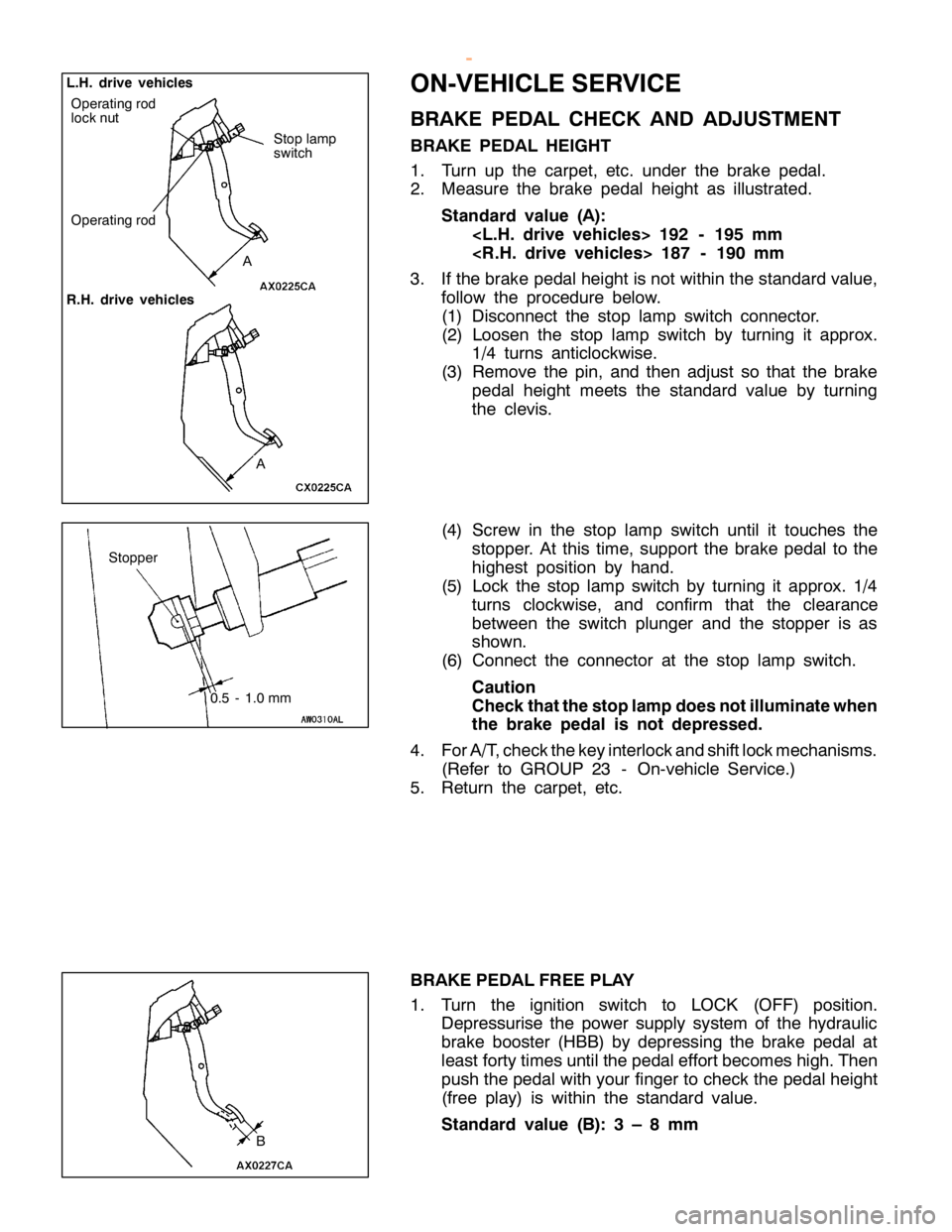
B RAKE PED AL CHEC K AND ADJU STM EN T
B RAKE PED AL HEIG HT
1 . Turn up th e ca rp et, etc . under th e bra ke pedal.
2 . Measu re th e bra ke pedal heig ht as illu str a te d.
S ta n dard valu e (A ):
< L .H . driv e veh ic le s> 192 -195 mm
< R .H . driv e veh ic le s> 187 -190 mm
3 . If th e bra ke pedalh eig ht is not w it h in th e sta ndard va lu e,
f o llo w th e pro ce dure belo w .
( 1 ) Dis co nnect th e sto p la m p sw it c h co nnecto r.
( 2 ) Loose n th e sto p la m p sw it c h by tu rn in g it appro x.
1 /4 tu rn s antic lo ckw is e .
( 3 ) Rem ove th e pin , and th en adju st so th at th e bra ke
p edal heig ht m eets th e sta ndard va lu e by tu rn in g
t h e cle vis .
( 4 ) Scre w in th e sto p la m p sw it c h until it to uch es th e
s to pper. A tth is tim e, su pport th e bra ke pedal to th e
h ig hest posit io n by hand.
( 5 ) Lock th e sto p la m p sw it c h by tu rn in g it appro x. 1/4
t u rn s clo ckw is e , and co nfir m th at th e cle ara nce
b etw een th e sw it c h plu nger and th e sto pper is as
s h ow n.
( 6 ) Connect th e co nnecto r at th e sto p la m p sw it c h .
C au tio n
C heck th atth e sto p la m pdoes notillu m in ate w hen
t h e bra ke ped al is not dep re ssed .
4 . ForA /T ,c h eck th e ke y in te rlo ck and sh if t lo ck m ech anis m s.
( R efe r to GRO UP 23 -On-v e hic le Serv ic e .)
5 . Retu rn th e ca rp et, etc .
B RAKE PED AL FR EE PLA Y
1 . Turn th e ig nit io n sw it c h to LO CK (O FF) posit io n.
D epre ssu ris e th e pow er su pply syste m of th e hyd ra ulic
b ra ke booste r (H BB) by depre ssin g th e bra ke pedal at
l e ast fo rty tim es until th e pedale ff o rt b eco m es hig h.T hen
p ush th e pedalw it h yo ur fin ger to ch eck th e pedalh eig ht
( fr e e pla y) is wit h in th e sta ndard va lu e.
S ta n dard valu e (B ): 3 –8mm A
L
.H .driv e veh ic le s
R .H .driv e veh ic le s O
pera tin g ro d S
to p la m p
s w it c h S
to pper
0.5 -1.0 mm B
w
ww.W ork sh opM an uals .c o .u k
P urc h ased f r o m w ww.W ork sh opM an uals .c o .u k
Page 1228 of 1839

Page 1229 of 1839

P
re ssu re
g auge
w
ww.W ork sh opM an uals .c o .u k
P urc h ased f r o m w ww.W ork sh opM an uals .c o .u k
Page 1230 of 1839

F
lu id pre ssu re at
f r o nt w heels M Pa F
lu id pre ssu re at
r e ar w heels M Pa 1
00 0
.6 or m ore 0
5
00 4
.5 or m ore 0
F
lu id pre ssu re at
f r o nt w heels M Pa F
lu id pre ssu re at
r e ar w heels M Pa 1
00 3
.0 -4.0 3
.3 -4.3 2
00 8
.0 -10.0 8
.0 -10.0 4
00 1
4.0 -18.0 1
4.0 -18.0 5
00 1
5.0 -19.0 1
5.0 -19.0