inspection procedure 13 MITSUBISHI MONTERO 2000 Service User Guide
[x] Cancel search | Manufacturer: MITSUBISHI, Model Year: 2000, Model line: MONTERO, Model: MITSUBISHI MONTERO 2000Pages: 1839, PDF Size: 29.19 MB
Page 273 of 1839
GDI -Troubleshooting
OK
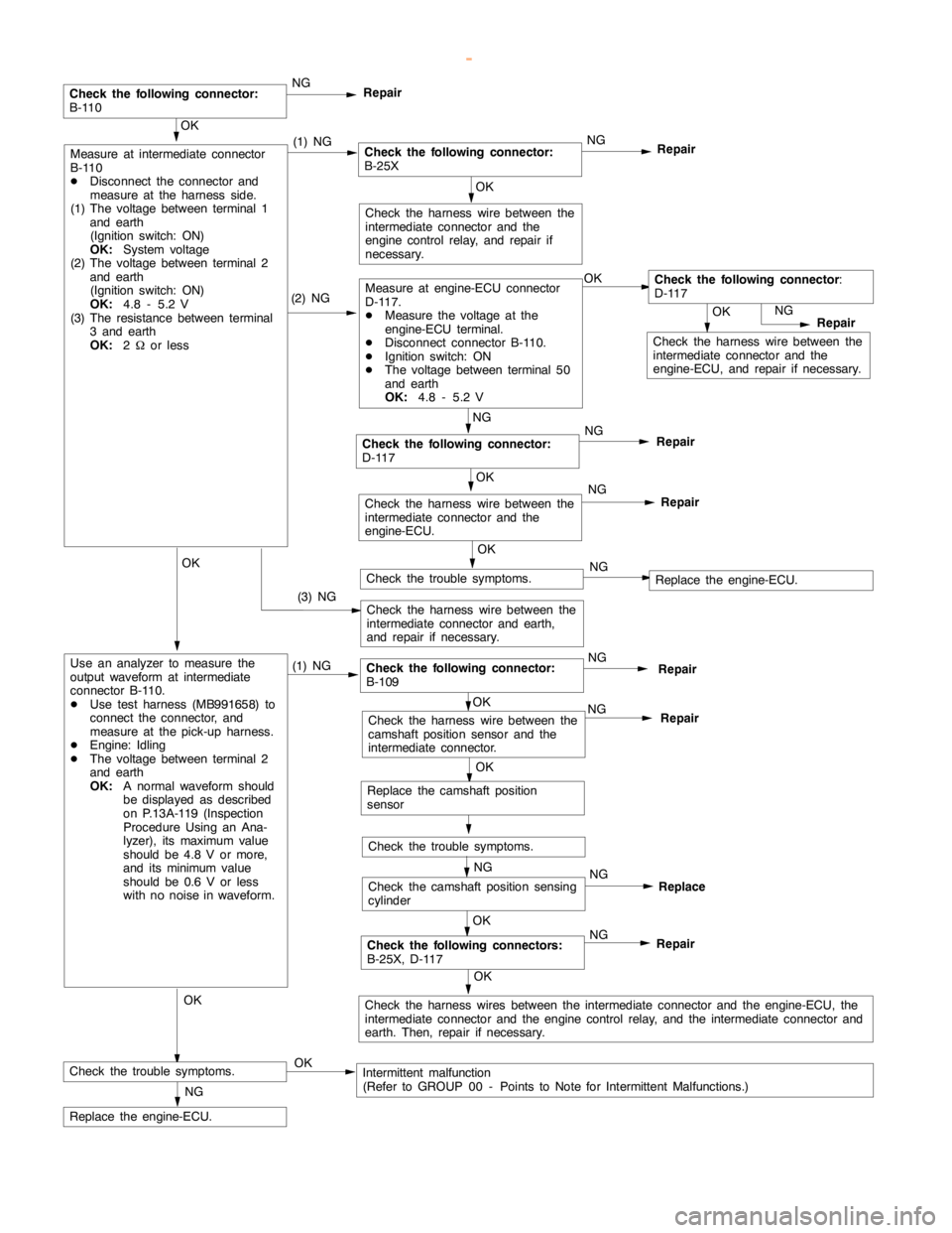
Check the harness wire between the
intermediate connector and the
engine-ECU, and repair if necessary.NG
Repair
NG
NG
Repair
NG
Repair
(2) NGMeasure at engine-ECU connector
D-117.
DMeasure the voltage at the
engine-ECU terminal.
DDisconnect connector B-110.
DIgnition switch: ON
DThe voltage between terminal 50
and earth
OK:
4.8 - 5.2 VOKCheck the following connector
:
D-117
Check the harness wire between the
intermediate connector and earth,
and repair if necessary.
OK
Check the harness wire between the
intermediate connector and the
engine controlrelay, and repair if
necessary.
(3) NG
OK
Measure at intermediate connector
B-110
DDisconnect the connector and
measure at the harness side.
(1) The voltage between terminal 1
and earth
(Ignition switch: ON)
OK:
System voltage
(2) The voltage between terminal 2
and earth
(Ignition switch: ON)
OK:
4.8 - 5.2 V
(3) The resistance between terminal
3 and earth
OK:
2Wor less(1) NGCheck the following connector:
B-25XNG
Repair
OK
Replace the camshaft position
sensor
Check the trouble symptoms.
OK
NG
Repair
OK
Check the harness wires between the intermediate connector and the engine-ECU, the
intermediate connector and theengine controlrelay, and the intermediate connector and
earth. Then, repair if necessary.
NG
Replace the engine-ECU.
OK
Check the harness wire between the
intermediate connector and the
engine-ECU.NG
Repair
OK
Use an analyzer to measure the
output waveform at intermediate
connector B-110.
DUse test harness (MB991658) to
connect the connector, and
measure at the pick-up harness.
DEngine: Idling
DThe voltage between terminal 2
and earth
OK:
A normal waveform should
be displayed as described
on P.13A-119 (Inspection
Procedure Using an Ana-
lyzer), its maximum value
should be 4.8 V or more,
and its minimumvalue
should be 0.6 V or less
with no noise in waveform.(1) NGCheck the following connector:
B-109NG
Repair
OK
Check the harness wire between the
camshaft position sensor and the
intermediate connector.NG
Repair
NG
Check the camshaft position sensing
cylinderNG
OK
Check the trouble symptoms.Intermittent malfunction
(Refer to GROUP 00 - Points to Note for Intermittent Malfunctions.)
OK
Check the trouble symptoms.NGReplace the engine-ECU.
Replace
OK
Check the following connector:
B-110
Check the following connector:
D-117
Check the following connectors:
B-25X, D-117
www.WorkshopManuals.co.uk
Purchased from www.WorkshopManuals.co.uk
Page 275 of 1839
GDI -Troubleshooting
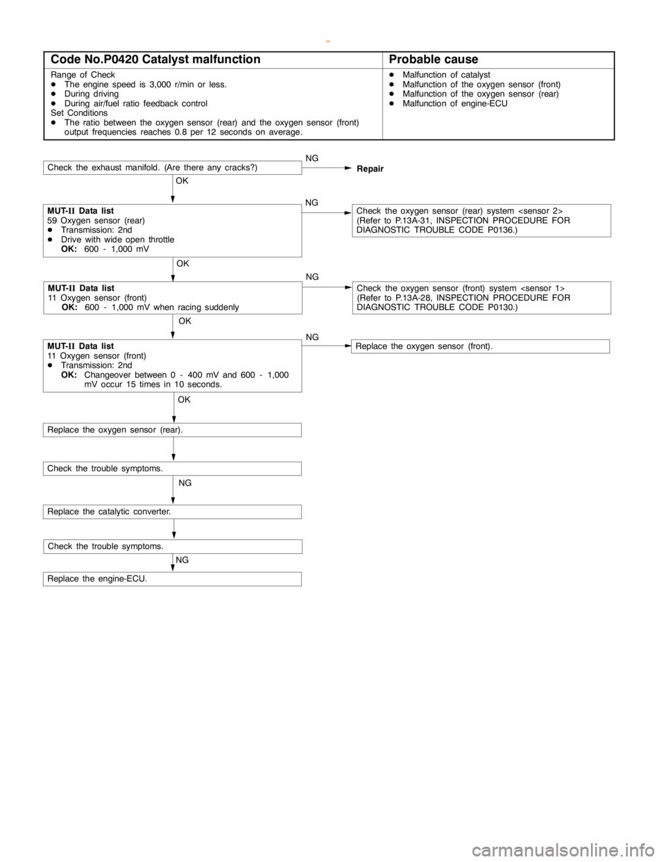
Code No.P0420 Catalyst malfunctionProbable cause
Range of Check
DThe enginespeed is 3,000 r/min or less.
DDuring driving
DDuring air/fuel ratio feedback control
Set Conditions
DThe ratio between the oxygen sensor (rear) and the oxygen sensor (front)
output frequencies reaches 0.8 per 12 seconds on average.DMalfunction of catalyst
DMalfunction of the oxygen sensor (front)
DMalfunction of the oxygen sensor (rear)
DMalfunction of engine-ECU
Check the trouble symptoms.
Check the exhaust manifold. (Are there anycracks?)NG
OK
MUT-
IIData list
59 Oxygen sensor (rear)
DTransmission: 2nd
DDrive with wideopen throttle
OK:
600 - 1,000 mVNGCheck the oxygen sensor (rear) system
(Refer to P.13A-31, INSPECTIONPROCEDURE FOR
DIAGNOSTIC TROUBLE CODE P0136.)
OK
MUT-
IIData list
11 Oxygen sensor (front)
DTransmission: 2nd
OK:
Changeover between 0 - 400 mV and 600 - 1,000
mV occur 15 times in 10 seconds.
OK
Replace the oxygen sensor (rear).
NG
Replace the catalytic converter.
Check the trouble symptoms.
NG
Replace the engine-ECU.
MUT-
IIData list
11 Oxygen sensor (front)
OK:
600 - 1,000 mV when racing suddenly
OK
NGRepair
Check the oxygen sensor (front) system
(Refer to P.13A-28, INSPECTIONPROCEDURE FOR
DIAGNOSTIC TROUBLE CODE P0130.)
Replace the oxygen sensor (front). NG
www.WorkshopManuals.co.uk
Purchased from www.WorkshopManuals.co.uk
Page 277 of 1839
GDI -Troubleshooting
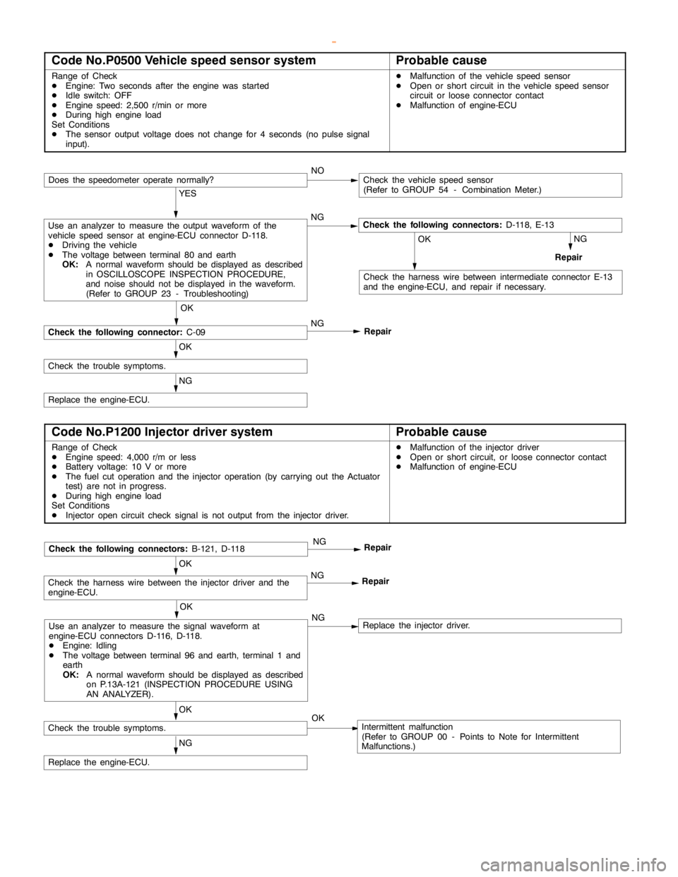
Code No.P0500 Vehicle speed sensor systemProbable cause
Range of Check
DEngine: Two seconds after theengine wasstarted
DIdle switch: OFF
DEngine speed: 2,500 r/min or more
DDuring high engine load
Set Conditions
DThe sensor output voltage does not change for 4 seconds (no pulse signal
input).DMalfunction of the vehicle speed sensor
DOpen or short circuit in the vehicle speed sensor
circuit or loose connector contact
DMalfunction of engine-ECU
NOCheck the vehicle speed sensor
(Refer to GROUP 54 - Combination Meter.)
YES
Use an analyzer to measure the output waveform of the
vehicle speed sensor at engine-ECU connector D-118.
DDriving the vehicle
DThe voltage between terminal 80 and earth
OK:
A normal waveform should be displayed as described
in OSCILLOSCOPE INSPECTION PROCEDURE,
and noise should not be displayed in the waveform.
(Refer to GROUP 23 - Troubleshooting)NGCheck the following connectors:
D-118, E-13
NG
Repair
OK
Check the harness wire between intermediate connector E-13
and the engine-ECU, and repair if necessary.
OK
Check the following connector:
C-09NG
Repair
OK
Check the trouble symptoms.
NG
Replace the engine-ECU.
Does the speedometer operate normally?
Code No.P1200 Injector driver systemProbable cause
Range of Check
DEngine speed: 4,000 r/m or less
DBattery voltage: 10 V or more
DThe fuel cut operation and the injector operation (by carrying out the Actuator
test) are not in progress.
DDuring high engine load
Set Conditions
DInjector opencircuit check signal is not output from the injector driver.DMalfunction of the injector driver
DOpen or short circuit, or loose connector contact
DMalfunction of engine-ECU
OK
Use an analyzer to measure the signal waveform at
engine-ECU connectors D-116, D-118.
DEngine: Idling
DThe voltage between terminal 96 and earth, terminal 1 and
earth
OK:
A normal waveform should be displayed as described
on P.13A-121 (INSPECTIONPROCEDURE USING
AN ANALYZER).NGReplace the injector driver.
OK
Check the harness wire between the injector driver and the
engine-ECU.NG
Repair
NG
Replace the engine-ECU.
Check the following connectors:
B-121, D-118NG
Repair
OK
Check the trouble symptoms.OKIntermittent malfunction
(Refer to GROUP 00 - Points to Note for Intermittent
Malfunctions.)
www.WorkshopManuals.co.uk
Purchased from www.WorkshopManuals.co.uk
Page 286 of 1839

GDI -Troubleshooting
INSPECTION CHART FOR TROUBLE SYMPTOMS
Trouble symptomInspection
procedure
No.Reference page
CommunicationCommunication with all systems is not possible.113A-74
with MUT-IIis
impossible.
Communication with engine-ECU only is not possible.213A-75
Engine warning
lamp andThe engine warning lamp does not illuminate right after the
ignition switch is turned to the ON position.313A-76
related parts
The engine warning lamp remains illuminating and never goes
out.413A-76
StartingNo initial combustion (starting impossible)513A-77
Initial combustion but no complete combustion
(starting impossible)613A-79
Long time to start (improper starting)
Idling stabilityUnstable idling (Rough idling, hunting)713A-81
(Improper idling)
Idling speed is high. (Improper idling speed)813A-83
Idling speed is low. (Improper idling speed)
Idling stabilityWhen the engine is cold, it stalls at idling. (Die out)913A-84
(Engine stalls)
When the engine is hot, it stalls at idling. (Die out)1013A-85
The engine stalls when starting the car. (Pass out)1113A-87
The engine stalls when decelerating.1213A-88
DrivingHesitation, sag or stumble1313A-89
Poor acceleration
Surge
The feeling of impact or vibration when accelerating1413A-90
The feeling of impact or vibration when decelerating1513A-91
Knocking1613A-91
Dieseling1713A-91
Too high CO and HC concentration when idling1813A-92
Low alternator output voltage (approx. 12.3 V)1913A-94
Engine idle speed is incorrect while the A/C is on.2013A-94
A/C condenser fan is inoperative2113A-95
Clutch switch system malfunction2213A-96
GDI ECO indi-GDI ECO indicator lamp does not illuminate.2313A-96
cator lamp sys-
tem
GDI ECO indicator lamp remains illuminated and does not go off.2413A-97
www.WorkshopManuals.co.uk
Purchased from www.WorkshopManuals.co.uk
Page 288 of 1839
GDI -Troubleshooting
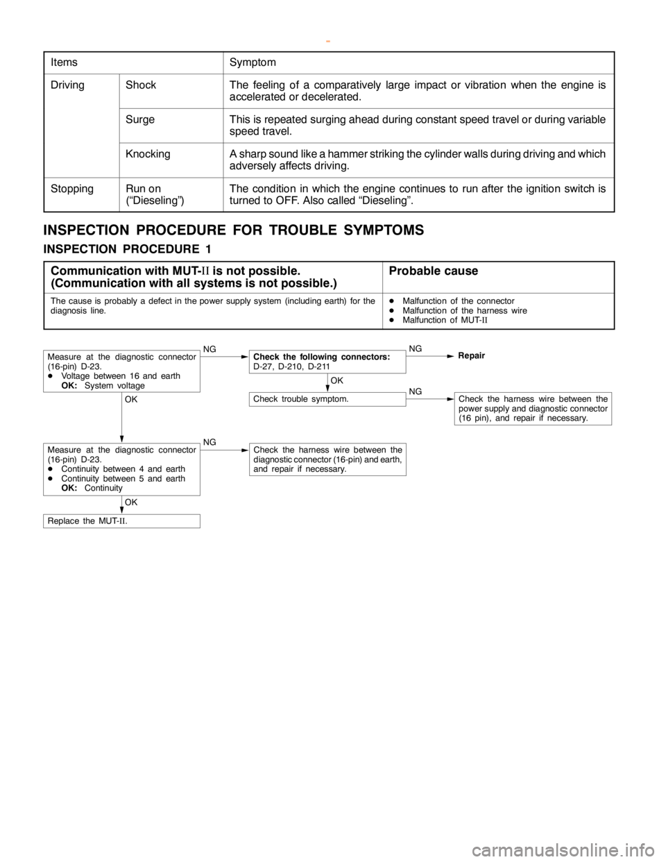
ItemsSymptom
DrivingShockThe feeling of a comparatively large impact or vibration when the engine is
accelerated or decelerated.
SurgeThis is repeated surging ahead during constant speed travel or during variable
speed travel.
KnockingA sharp sound like a hammer striking the cylinder walls during driving and which
adversely affects driving.
StoppingRun on
(“Dieseling”)The condition in which the engine continues to run after the ignition switch is
turned to OFF. Also called “Dieseling”.
INSPECTION PROCEDURE FOR TROUBLE SYMPTOMS
INSPECTION PROCEDURE 1
Communication with MUT-II
is not possible.
(Communication with all systems is not possible.)
Probable cause
The cause is probably a defect in the power supply system (including earth) for the
diagnosis line.DMalfunction of the connector
DMalfunction of the harness wire
DMalfunction of MUT-
II
Measure at the diagnostic connector
(16-pin) D-23.
DVoltage between 16 and earth
OK:System voltageNGCheck the following connectors:
D-27, D-210, D-211NG
Repair
OK
Check trouble symptom.NGCheck the harness wire between the
power supply and diagnostic connector
(16 pin), and repair if necessary.OK
Measure at the diagnostic connector
(16-pin) D-23.
DContinuity between 4 and earth
DContinuity between 5 and earth
OK:ContinuityNGCheck the harness wire between the
diagnostic connector (16-pin) and earth,
and repair if necessary.
OK
Replace the MUT-
II.
www.WorkshopManuals.co.uk
Purchased from www.WorkshopManuals.co.uk
Page 289 of 1839
GDI -Troubleshooting
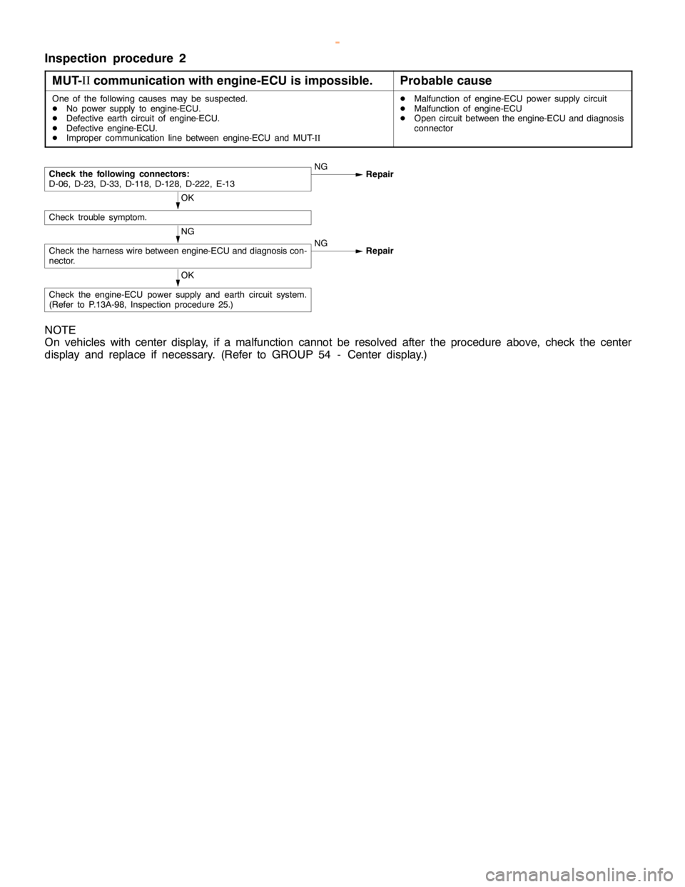
Inspection procedure 2
MUT-II
communication with engine-ECU is impossible.
Probable cause
One of the following causes may be suspected.
DNo power supply to engine-ECU.
DDefective earth circuit of engine-ECU.
DDefective engine-ECU.
DImproper communication line between engine-ECU and MUT-IIDMalfunction of engine-ECU power supply circuit
DMalfunction of engine-ECU
DOpen circuit between the engine-ECU and diagnosis
connector
NG
Check the harness wire between engine-ECU and diagnosis con-
nector.NG
Repair
OK
Check trouble symptom.
Check the following connectors:
D-06, D-23, D-33, D-118, D-128, D-222, E-13NG
Repair
OK
Check the engine-ECU power supply and earth circuit system.
(Refer to P.13A-98, Inspection procedure 25.)
NOTE
On vehicles with center display, if a malfunction cannot be resolved after the procedure above, check the center
display and replace if necessary. (Refer to GROUP 54 - Center display.)
www.WorkshopManuals.co.uk
Purchased from www.WorkshopManuals.co.uk
Page 290 of 1839
GDI -Troubleshooting
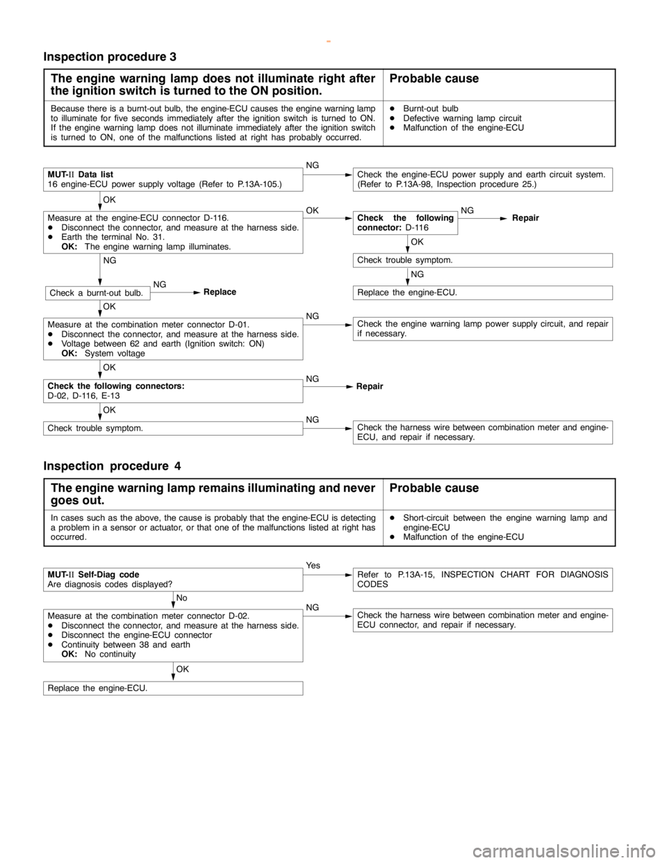
Inspection procedure 3
The engine warning lamp does not illuminate right after
the ignition switch is turned to the ON position.
Probable cause
Because there is a burnt-out bulb, the engine-ECU causes theengine warning lamp
to illuminate forfive seconds immediately after the ignition switch is turned to ON.
If the engine warning lampdoes notilluminate immediately after the ignitionswitch
is turned to ON, one of the malfunctions listed at right has probably occurred.DBurnt-out bulb
DDefective warninglampcircuit
DMalfunction of the engine-ECU
MUT-
IIData list
16 engine-ECU power supply voltage (Refer to P.13A-105.)NGCheck the engine-ECU power supply and earth circuit system.
(Refer to P.13A-98, Inspection procedure 25.)
OK
Measure at the engine-ECU connector D-116.
DDisconnect the connector, and measure at the harness side.
DEarth the terminal No. 31.
OK:
The engine warning lamp illuminates.OKCheck the following
connector:
D-116NG
Repair
OK
Check trouble symptom.
NG
Replace the engine-ECU.
NG
Check a burnt-out bulb.NG
Replace
OK
Measure at the combination meter connector D-01.
DDisconnect the connector, and measure at the harness side.
DVoltage between 62 and earth (Ignition switch: ON)
OK:
System voltageNGCheck theengine warning lamppower supply circuit, and repair
if necessary.
OK
Check the following connectors:
D-02, D-116, E-13NG
Repair
OK
Check trouble symptom.NGCheck the harness wire between combination meter and engine-
ECU, and repair if necessary.
Inspection procedure 4
The engine warning lamp remains illuminating and never
goes out.
Probable cause
In cases such as the above, the cause is probably that the engine-ECU is detecting
a problem in a sensor or actuator, or that one of the malfunctions listed at right has
occurred.DShort-circuit between the engine warning lamp and
engine-ECU
DMalfunction of the engine-ECU
MUT-
IISelf-Diag code
Are diagnosis codes displayed?Ye sRefer to P.13A-15, INSPECTION CHART FOR DIAGNOSIS
CODES
No
Measure at the combination meter connector D-02.
DDisconnect the connector, and measure at the harness side.
DDisconnect the engine-ECU connector
DContinuity between 38 and earth
OK:
No continuityNGCheck the harness wire between combination meter and engine-
ECU connector, and repair if necessary.
OK
Replace the engine-ECU.
www.WorkshopManuals.co.uk
Purchased from www.WorkshopManuals.co.uk
Page 291 of 1839
GDI -Troubleshooting
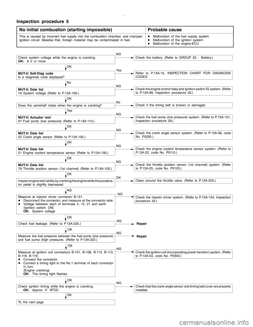
Inspection procedure 5
No initial combustion (starting impossible)
Probable cause
This is caused by incorrect fuel supply into the combustion chamber, and improper
ignition circuit. Besides that, foreign material may be contaminated in fuel.DMalfunction of the fuel supply system
DMalfunction of the ignition system
DMalfunction of the engine-ECU
Check system voltage while theengine iscranking.
OK:
8 V or moreNGCheck the battery. (Refer to GROUP 55 - Battery.)
OK
MUT-
IISelf-Diag code
Is a diagnosis code displayed?Ye sRefer to P.13A-15, INSPECTION CHART FOR DIAGNOSIS
CODES.
No
MUT-
IIData list
16 System voltage (Refer to P.13A-105.)NGCheck theengine controlrelay and ignition switch-IG system. (Refer
to P.13A-99, Inspection procedure 26.)
OK
Does the camshaft rotate when theengine is cranking?NoCheck if thetiming belt isbroken ordamaged.
Ye s
MUT-
IIActuator test
07 Fuel pump(low pressure) (Refer to P.13A-110.)NGCheck the fuelpump(low pressure) system. (Refer to P.13A-101,
Inspection procedure 29.)
OK
MUT-
IIData list
22 Crankanglesensor (Refer to P.13A-105.)NGCheck the crankanglesensor system. (Refer to P.13A-56, code
No. P0335.)
OK
MUT-
IIData list
21 Engine coolant temperature sensor (Refer to P.13A-105.)NGCheck theengine coolant temperaturesensor system. (Refer to
P.13A-22, code No. P0115.)
OK
MUT-
IIData list
79 Throttle position sensor (1st channel) (Refer to P.13A-105.)NGCheck the throttle position sensor (1st channel) system. (Refer
to P.13A-25, code No. P0120.)
OK
Inspectenginestart ability by cranking theengine while theaccelera-
tor pedal isslightly depressed.OKClean around the throttle valve. (Refer to P.13A-220.)
NG
Check fuel leakage. (Refer to P.13A-225.)NG
Repair
OK
Measure low fuel pressure between the fuelpump(low pressure)
and fuel pump (highpressure). (Refer to P.13A-222.)NG
Repair
OK
Measure at ignition coil connectors B-101, B-108, B-112, B-113,
B-116, B-119.
DConnect the connector.
DConnect atiming light to theNo.1 terminal of each connector
in turn.
(Engine cranking)
OK:
The timing lightflashes.NGCheck the ignition coil (incorporating power transitor) system. (Refer
to P.13A-53, code No. P0300.)
OK
Check ignitiontiming while the engine iscranking.
OK:
Approx. 5_BTDCNGCheck that the crankanglesensor andtiming beltcover are properly
installed.
OK
To the nextpage
Measure at injector driver connector B-121.
DDisconnect the connector, and measure at the connector side.
DVoltage between each of terminals 4, 12, 21 and earth
(Ignition switch: ON)
OK:
System voltageCheck the injector driver system. (Refer to P.13A-104, Inspection
procedure 34.) NG
OK
www.WorkshopManuals.co.uk
Purchased from www.WorkshopManuals.co.uk
Page 293 of 1839
GDI -Troubleshooting
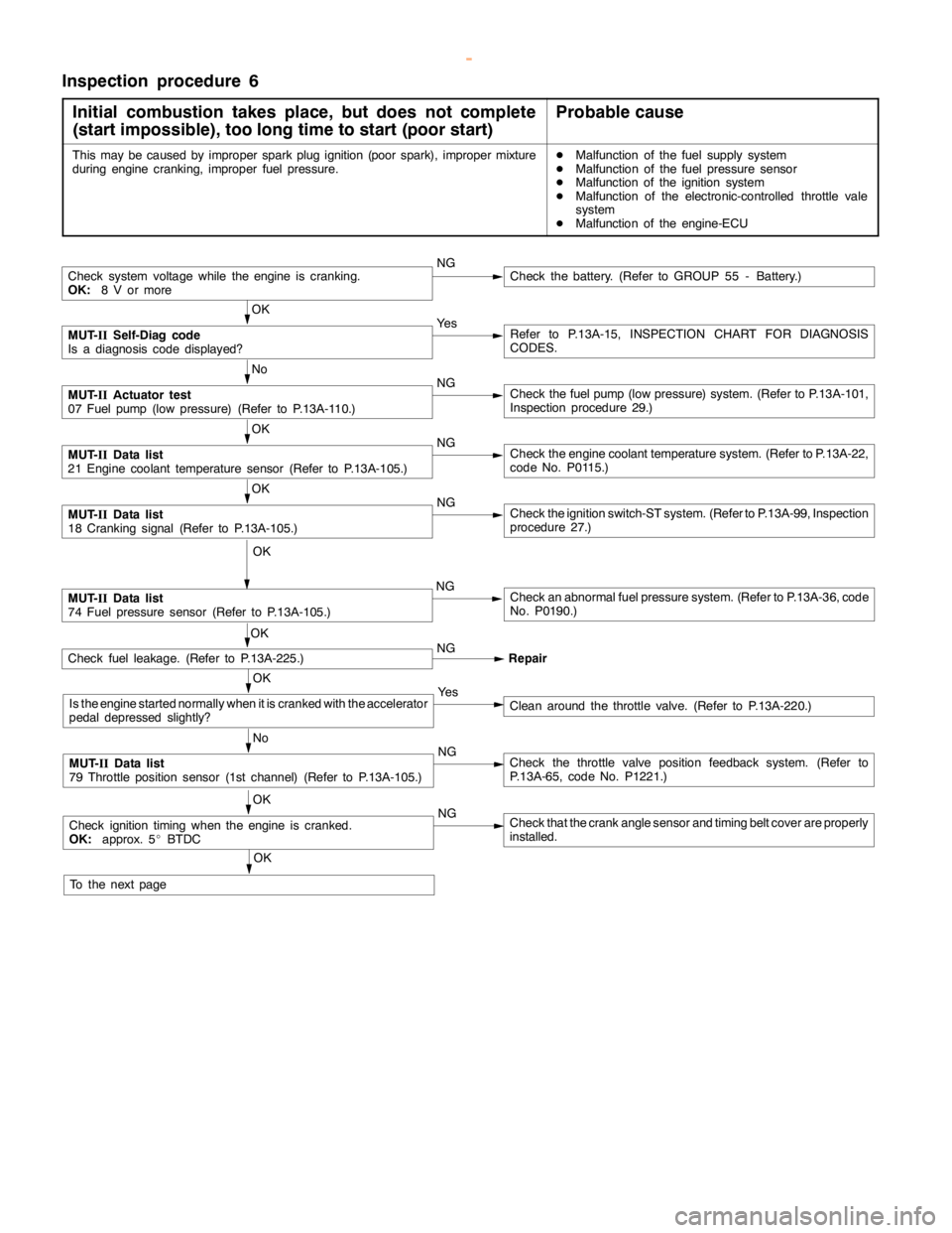
Inspection procedure 6
Initial combustion takes place, but does not complete
(start impossible), too long time to start (poor start)
Probable cause
This may be caused by improper sparkplug ignition (poorspark), improper mixture
during enginecranking, improper fuel pressure.DMalfunction of the fuel supply system
DMalfunction of the fuel pressure sensor
DMalfunction of the ignition system
DMalfunction of the electronic-controlled throttle vale
system
DMalfunction of the engine-ECU
Check system voltage while theengine iscranking.
OK:
8 V or moreNGCheck the battery. (Refer to GROUP 55 - Battery.)
OK
MUT-
IISelf-Diag code
Is a diagnosis code displayed?Ye sRefer to P.13A-15, INSPECTION CHART FOR DIAGNOSIS
CODES.
No
MUT-
IIActuator test
07 Fuel pump(low pressure) (Refer to P.13A-110.)NGCheck the fuelpump(low pressure) system. (Refer to P.13A-101,
Inspection procedure 29.)
OK
MUT-
IIData list
21 Engine coolant temperature sensor (Refer to P.13A-105.)NGCheck theengine coolant temperaturesystem. (Refer to P.13A-22,
code No. P0115.)
OK
MUT-
IIData list
18 Cranking signal (Refer to P.13A-105.)NGCheck the ignition switch-ST system. (Refer to P.13A-99, Inspection
procedure 27.)
OK
MUT-
IIData list
74 Fuel pressure sensor (Refer to P.13A-105.)NGCheck an abnormal fuel pressure system. (Refer to P.13A-36, code
No. P0190.)
Check fuel leakage. (Refer to P.13A-225.)NG
Repair
OK
Is the enginestarted normally when it is cranked with the accelerator
pedal depressed slightly?Ye sClean around the throttle valve. (Refer to P.13A-220.)
No
MUT-
IIData list
79 Throttle position sensor (1st channel) (Refer to P.13A-105.)NGCheck the throttle valve position feedback system. (Refer to
P.13A-65, code No. P1221.)
OK
Check ignitiontimingwhen theengine iscranked.
OK:
approx. 5_BTDCNGCheck that the crankanglesensor andtiming beltcover are properly
installed.
OK
To the nextpageOK
www.WorkshopManuals.co.uk
Purchased from www.WorkshopManuals.co.uk
Page 295 of 1839
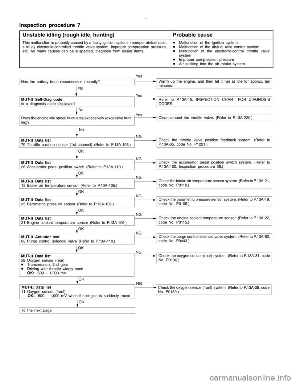
GDI -Troubleshooting
Inspection procedure 7
Unstable idling (rough idle, hunting)
Probable cause
This malfunction is probably caused by a faulty ignition system, improper air/fuel ratio,
a faulty electronic-controlled throttle valve system, improper compression pressure,
etc. As many causes can be suspected, diagnose from easier items.DMalfunction of the ignition system
DMalfunction of the air/fuel ratio control system
DMalfunction of the electronic-control throttle valve
system
DImproper compression pressure
DAir sucking into the air intake system
Has the batterybeen disconnectedrecently?Ye sWarm up the engine, and then let it run at idle for approx. ten
minutes.
No
MUT-
IISelf-Diag code
Is a diagnosis code displayed?Ye sRefer to P.13A-15, INSPECTION CHART FOR DIAGNOSIS
CODES.
No
Does theengine idlespeed fluctuates excessively (excessivehunt-
ing)?Ye sClean around the throttle valve. (Refer to P.13A-220.)
No
MUT-
IIData list
79 Throttle position sensor (1st channel) (Refer to P.13A-105.)NGCheck the throttle valve position feedback system. (Refer to
P.13A-65, code No. P1221.)
OK
MUT-
IIData list
26 Acceleratorpedal positionswitch (Refer to P.13A-110.)NGCheck the acceleratorpedal positionswitch system. (Refer to
P.13A-100, Inspection procedure 28.)
OK
MUT-
IIData list
13 Intake air temperature sensor (Refer to P.13A-105.)NGCheck the intake air temperature sensor system. (Refer to P.13A-21,
code No. P0110.)
OK
MUT-
IIData list
25 Barometric pressure sensor (Refer to P.13A-105.)NGCheck the barometric pressure sensor system. (Refer to P.13A-19,
code No. P0105.)
OK
MUT-
IIData list
21 Engine coolant temperature sensor (Refer to P.13A-105.)NGCheck theengine coolant temperaturesensor. (Refer to P.13A-22,
code No. P0115.)
OK
MUT-
IIActuator test
08 Purge control solenoid valve (Refer to P.13A-110.)NGCheck the purge control solenoid valve system. (Refer to P.13A-62,
code No. P0443.)
OK
MUT-
IIData list
11 Oxygen sensor (front)
OK:
600 - 1,000 mV when theengine is suddenlyracedNGCheck the oxygen sensor (front) system. (Refer to P.13A-28, code
No. P0130.)
OK
MUT-
IIData list
59 Oxygen sensor (rear)
DTransmission: 2nd gear
DDriving with throttle widelyopen
OK:
600 - 1,000 mVNGCheck the oxygen sensor (rear) system. (Refer to P.13A-31, code
No. P0136.)
OK
To the nextpage
www.WorkshopManuals.co.uk
Purchased from www.WorkshopManuals.co.uk