inspection procedure 13 MITSUBISHI MONTERO 2000 Service Repair Manual
[x] Cancel search | Manufacturer: MITSUBISHI, Model Year: 2000, Model line: MONTERO, Model: MITSUBISHI MONTERO 2000Pages: 1839, PDF Size: 29.19 MB
Page 2 of 1839

00-1
GENERAL
CONTENTS
HOW TO USE THIS MANUAL 2..............
Scope of Maintenance, Repair and Servicing
Explanations 2.................................
Definition of Terms 2...........................
Indication of Tightening Torque 2................
Model Indications 3............................
Explanation of Manual Contents 4...............
HOW TO USE
TROUBLESHOOTING/INSPECTION SERVICE
POINTS 6....................................
Troubleshooting Contents 6.....................
Diagnosis Function 7...........................
How to Use the Inspection Procedures 10.......
Connector Measurement Service Points 11.......
Connector Inspection 12........................
Inspection Service Points for a Blown Fuse 13...
Points to Note for Intermittent Malfunctions 13....
TREATMENT BEFORE/AFTER THE FORDING
A STREAM 14..............................
Inspection and Service before Fording a Stream
14 ............................................
Inspection and Service after Fording a Stream
15 ............................................
VEHICLE IDENTIFICATION 16...............
Vehicle Information Code Plate 16...............
Models 16.....................................
Model Code 18................................
Chassis Number 19............................
Engine Model Number 20.......................
Theft Protection
MAJOR SPECIFICATIONS 23................
PRECAUTIONS BEFORE SERVICE 29.......
SUPPLEMENTAL RESTRAINT SYSTEM
(SRS) 33....................................
SUPPORT LOCATIONS FOR LIFTING AND
JACKING 37................................
Support Positions for a Garage Jack 37.........
Support Positions for axle stands and a
Single-Post Lift or Double-Post Lift 38...........
STANDARD PARTS-TIGHTENING-TORQUE
TABLE 39..................................
www.WorkshopManuals.co.uk
Purchased from www.WorkshopManuals.co.uk
Page 3 of 1839

GENERAL -How to Use This Manual00-2
HOW TO USE THIS MANUAL
SCOPE OF MAINTENANCE, REPAIR
AND SERVICING EXPLANATIONS
This manual provides explanations, etc. concerning
procedures for the inspection, maintenance, repair
and servicing of the subject model. Note, however,
that for engine and transmission-related component
parts, this manual covers only on-vehicle
inspections, adjustments, and the removal and
installation procedures for major components.
For detailed information concerning the inspection,
checking, adjustment, disassembly and reassembly
of the engine, transmission and major components
after they have been removed from the vehicle,
please refer to separate manuals covering the
engine and the transmission.
ON-VEHICLE SERVICE
“On-vehicle Service” is procedures for performing
inspections and adjustments of particularly
important locations with regard to the construction
and for maintenance and servicing, but other
inspection (for looseness, play, cracking, damage,
etc.) must also be performed.
INSPECTION
Under this title are presented inspection and
checking procedures to be performed by using
special tools and measuring instruments and by
feeling, but, for actual maintenance and servicing
procedures, visual inspections should always be
performed as well.
DEFINITION OF TERMS
STANDARD VALUE
Indicates the value used as the standard for judging
the quality of a part or assembly on inspection
or the value to which the part or assembly is
corrected and adjusted. It is given by tolerance.
LIMIT
Shows the standard for judging the quality of a
part or assembly on inspection and means the
maximum or minimum value within which the part
or assembly must be kept functionally or in strength.
It is a value established outside the range of
standard value.
REFERENCE VALUE
Indicates the adjustment value prior to starting the
work (presented in order to facilitate assembly and
adjustment procedures, and so they can be
completed in a shorter time).
CAUTION
Indicates the presentation of information particularly
vital to the worker during the performance of
maintenance and servicing procedures in order to
avoid the possibility of injury to the worker, or
damage to component parts, or a reduction of
component or vehicle function or performance, etc.
INDICATION OF TIGHTENING TORQUE
Tightening torques (units: N×m) are set to take into
account the central value and the allowable
tolerance. The central value is the target value,
and the allowable tolerance provides the checking
range for tightening torques. If bolts and nuts are
not provided with tightening torques, refer to
P.00-39.
www.WorkshopManuals.co.uk
Purchased from www.WorkshopManuals.co.uk
Page 7 of 1839
GENERAL -How to Use Troubleshooting/Inspection Service Points00-6
HOW TO USE TROUBLESHOOTING/INSPECTION SERVICE
POINTS
Troubleshooting of electronic control systems for which the MUT-IIcan be used follows the basic outline
described below. Furthermore, even in systems for which the MUT-IIcannot be used, part of these systems
still follow this outline.
TROUBLESHOOTING CONTENTS
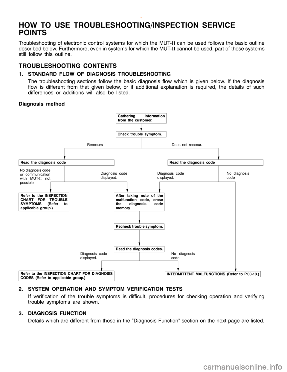
1. STANDARD FLOW OF DIAGNOSIS TROUBLESHOOTING
The troubleshooting sections follow the basic diagnosis flow which is given below. If the diagnosis
flow is different from that given below, or if additional explanation is required, the details of such
differences or additions will also be listed.
Diagnosis method
Gathering information
from the customer.
Check trouble symptom.
Reoccurs Does not reoccur.
Read the diagnosis code
No diagnosis code
or communication
with MUT-
IInot
possible
Refer to the INSPECTION
CHART FOR TROUBLE
SYMPTOMS (Refer to
applicable group.)Diagnosis code
displayed.
Read the diagnosis code
Diagnosis code
displayed.No diagnosis
code
After taking note of the
malfunction code, erase
the diagnosis code
memory
Recheck trouble symptom.
Diagnosis code
displayed.
Read the diagnosis codes.
No diagnosis
code
Refer to the INSPECTION CHART FOR DIAGNOSIS
CODES (Refer to applicable group.)INTERMITTENT MALFUNCTIONS (Refer to P.00-13.)
2. SYSTEM OPERATION AND SYMPTOM VERIFICATION TESTS
If verification of the trouble symptoms is difficult, procedures for checking operation and verifying
trouble symptoms are shown.
3. DIAGNOSIS FUNCTION
Details which are different from those in the “Diagnosis Function” section on the next page are listed.
www.WorkshopManuals.co.uk
Purchased from www.WorkshopManuals.co.uk
Page 11 of 1839
GENERAL -How to Use Troubleshooting/Inspection Service Points00-10
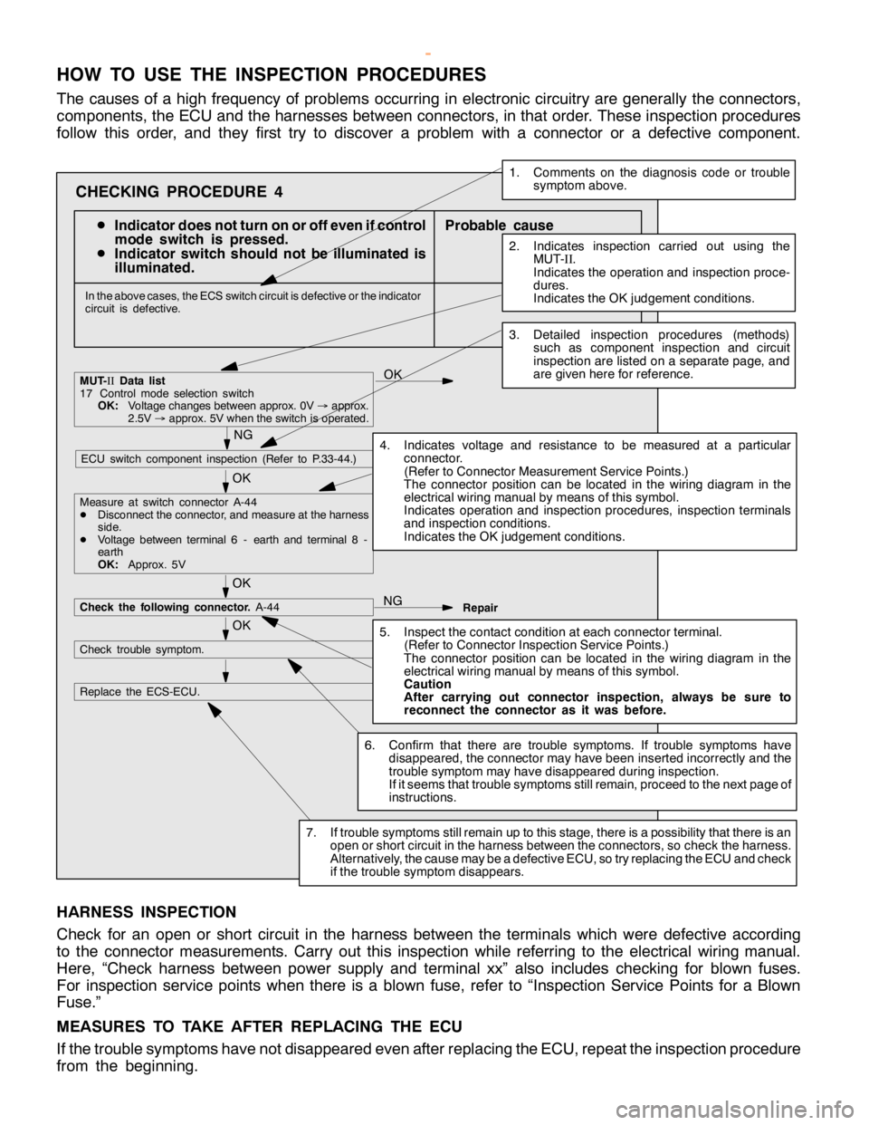
HOW TO USE THE INSPECTION PROCEDURES
The causes of a high frequency of problems occurring in electronic circuitry are generally the connectors,
components, the ECU and the harnesses between connectors, in that order. These inspection procedures
follow this order, and they first try to discover a problem with a connector or a defective component.
D
Indicator does not turn on or off even if control
mode switch is pressed.
D
Indicator switch should not be illuminated is
illuminated.Probable cause
OK
OK
OK
Measure at switch connector A-44
DDisconnect the connector, and measure at the harness
side.
DVoltage between terminal 6 - earth and terminal 8 -
earth
OK:Approx. 5V
OK
NG
Check the following connector.A-44
Repair
OK
Check trouble symptom.
Replace the ECS-ECU.
In the above cases, the ECS switch circuit is defective or the indicator
circuit is defective.
CHECKING PROCEDURE 4
2. Indicates inspection carried out using the
MUT-
II.
Indicates the operation and inspection proce-
dures.
Indicates the OK judgement conditions.
3. Detailed inspection procedures (methods)
such as component inspection andcircuit
inspection are listed on a separate page, and
are given here for reference.
5. Inspect the contact condition at each connectorterminal.
(Refer to Connector Inspection Service Points.)
The connector position can be located in the wiring diagram in the
electrical wiring manual bymeans ofthis symbol.
Caution
After carrying out connector inspection, always be sure to
reconnect the connector as it was before.
6. Confirm that there are trouble symptoms. If trouble symptomshave
disappeared, the connector may have been inserted incorrectly and the
trouble symptom mayhave disappeared during inspection.
If it seemsthat trouble symptoms still remain, proceed to the nextpage of
instructions.
7. If trouble symptoms still remain up to this stage, there is a possibility that there is an
open orshort circuit in the harness between the connectors, socheck the harness.
Alternatively, the cause may be a defectiveECU, so try replacing the ECU andcheck
if the trouble symptom disappears.
NGECU switch component inspection (Refer to P.33-44.)
NG
1. Comments on the diagnosis code ortrouble
symptom above.
MUT-II
Data list
17 Control mode selectionswitch
OK:Voltage changes between approx. 0V
®approx.
2.5V
®approx. 5V when the switch is operated.
4. Indicates voltage and resistance to be measured at a particular
connector.
(Refer to Connector Measurement Service Points.)
The connector position can be located in the wiring diagram in the
electrical wiring manual bymeans ofthis symbol.
Indicates operation and inspection procedures, inspection terminals
and inspection conditions.
Indicates the OK judgement conditions.
HARNESS INSPECTION
Check for an open or short circuit in the harness between the terminals which were defective according
to the connector measurements. Carry out this inspection while referring to the electrical wiring manual.
Here, “Check harness between power supply and terminal xx” also includes checking for blown fuses.
For inspection service points when there is a blown fuse, refer to “Inspection Service Points for a Blown
Fuse.”
MEASURES TO TAKE AFTER REPLACING THE ECU
If the trouble symptoms have not disappeared even after replacing the ECU, repeat the inspection procedure
from the beginning.
www.WorkshopManuals.co.uk
Purchased from www.WorkshopManuals.co.uk
Page 36 of 1839

GENERAL -Supplemental Restraint System (SRS)00-35
SRS-ECU
Terminal No.Destination of harnessCorrective action
1, 2, 3, 4Instrument panel wiring harness®Front wiring harness®Front
impact sensorRepair or replace each wiring
harness
7Instrument panel wiring harness®EarthRepair or replace Instrument
8Instrument panel wiring harness®Combination meter
(SRS warning lamp)
panel wiring harness
9, 10Instrument panel wiring harness®Front passenger’s air bag
module
11 , 1 2Instrument panel wiring harness®Clock spring®Driver’s air bag
module)Repair or replace the Instrument
panel wiring harness. Replace
clock spring.
13Instrument panel wiring harness®Junction block (fuse No.8)Repair or replace Instrument
16Instrument panel wiring harness®Junction block (fuse No.6)
panel wiring harness.
20Instrument panel wiring harness®Diagnosis connector
21, 22Side air bag wiring harness®Side air bag module (L.H.)Repair or replace side air bag
23, 24Side air bag wiring harness®Side air bag module (R.H.)
wiring harness.
34, 35, 36Side air bag wiring harness®Floor wiring harness®Side impact
sensor (L.H.)Repair or each wiring harness.
40, 41, 42Side air bag wiring harness®Floor wiring harness®Side impact
sensor (R.H.)
6. Inspection of the SRS-ECU harness connector should be carried out by the following procedure.
Insert the special tool (probe, MB991222, in the harness set) into the connector from harness side
(rear side), and connect the tester to this probe. If any tool than specified is used, damage to the
harness and other components will result. Furthermore, measurement should not be carried out by
touching the probe directly against the terminals from the front of the connector. The terminals are
plated to increase their conductivity, so that if they are touched directly by the probe, the plating
may break, which will cause drops in reliability.
www.WorkshopManuals.co.uk
Purchased from www.WorkshopManuals.co.uk
Page 231 of 1839
GDI -Troubleshooting
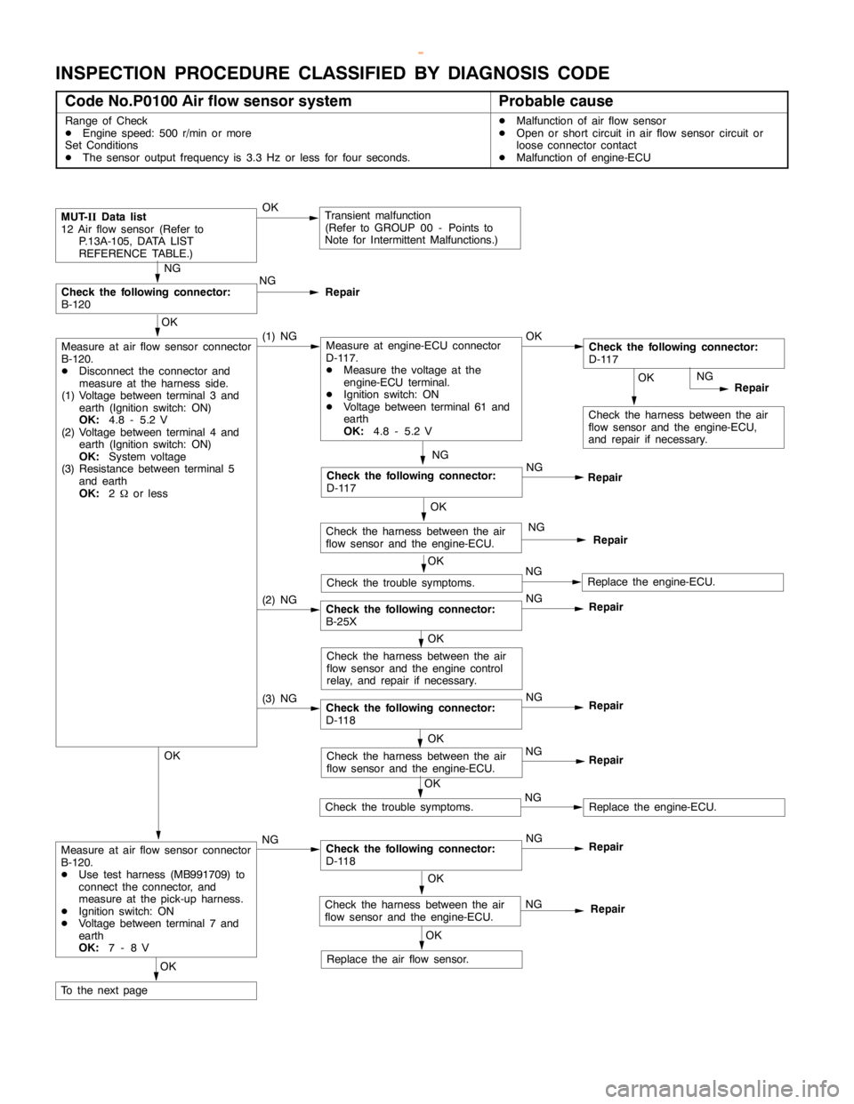
INSPECTION PROCEDURE CLASSIFIED BY DIAGNOSIS CODE
Code No.P0100 Air flow sensor systemProbable cause
Range of Check
DEngine speed: 500 r/min or more
Set Conditions
DThe sensor output frequency is 3.3 Hz or less for four seconds.DMalfunction of air flow sensor
DOpen or short circuit in air flow sensor circuit or
loose connector contact
DMalfunction of engine-ECU
(3) NGCheck the following connector:
D-118NG
Repair
(2) NGCheck the following connector:
B-25XNG
Repair
OK
Check the harness between the air
flow sensor and the engine-ECU,
and repair if necessary.
MUT-
IIData list
12 Air flow sensor (Refer to
P.13A-105, DATA LIST
REFERENCE TABLE.)OKTransient malfunction
(Refer to GROUP 00 - Points to
Note for Intermittent Malfunctions.)
NG
Check the following connector:
B-120NG
Repair
OK
Measure at air flow sensor connector
B-120.
DDisconnect the connector and
measure at the harness side.
(1) Voltage between terminal 3 and
earth (Ignition switch: ON)
OK:
4.8 - 5.2 V
(2) Voltage between terminal 4 and
earth (Ignition switch: ON)
OK:
System voltage
(3) Resistance between terminal 5
and earth
OK:
2Wor less(1) NGMeasure at engine-ECU connector
D-117.
DMeasure the voltage at the
engine-ECU terminal.
DIgnition switch: ON
DVoltage between terminal 61 and
earth
OK:
4.8 - 5.2 VOKCheck the following connector:
D-117
NG
Repair
OK
Replace the air flow sensor.
NG
Check the following connector:
D-117NG
Repair
OK
Check the harness between the air
flow sensor and the engine-ECU.NG
Repair
OK
Check the trouble symptoms.NGReplace the engine-ECU.
OK
Check the harness between the air
flow sensor and theengine control
relay, and repair if necessary.
OK
Check the harness between the air
flow sensor and the engine-ECU.NG
Repair
OK
Check the trouble symptoms.NGReplace the engine-ECU.
OK
Measure at air flow sensor connector
B-120.
DUse test harness (MB991709) to
connect the connector, and
measure at the pick-up harness.
DIgnition switch: ON
DVoltage between terminal 7 and
earth
OK:
7-8VNGCheck the following connector:
D-118NG
Repair
OK
Check the harness between the air
flow sensor and the engine-ECU.NG
Repair
OK
To the nextpage
www.WorkshopManuals.co.uk
Purchased from www.WorkshopManuals.co.uk
Page 248 of 1839
GDI -Troubleshooting
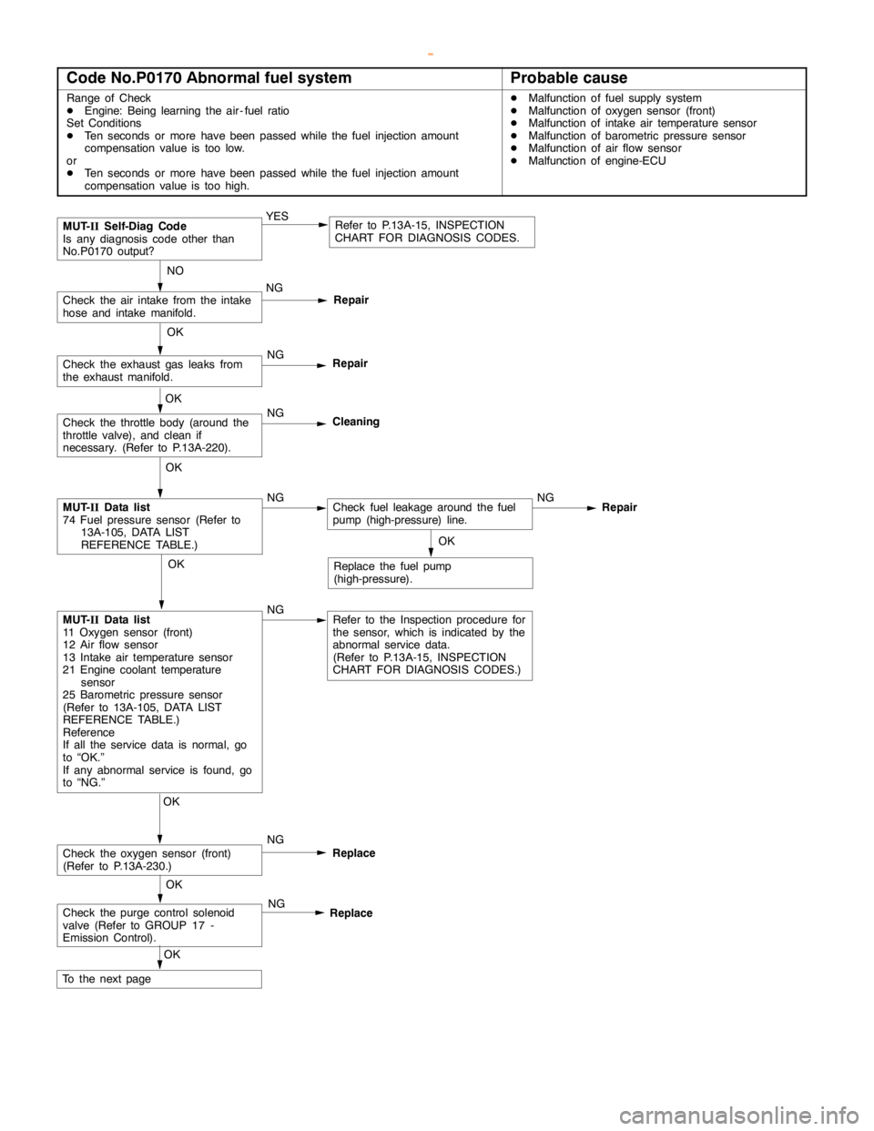
Code No.P0170 Abnormal fuel systemProbable cause
Range of Check
DEngine: Being learning the air - fuel ratio
Set Conditions
DTen seconds or more havebeenpassed while the fuel injection amount
compensation value is too low.
or
DTen seconds or more havebeenpassed while the fuel injection amount
compensation value is too high.DMalfunction of fuel supply system
DMalfunction of oxygen sensor (front)
DMalfunction of intake air temperature sensor
DMalfunction of barometric pressure sensor
DMalfunction of air flow sensor
DMalfunction of engine-ECU
Repair
OK
MUT-
IIData list
74 Fuel pressure sensor (Refer to
13A-105, DATA LIST
REFERENCE TABLE.)NGCheck fuel leakage around the fuel
pump (high-pressure) line.NG
NO
Check the air intake from the intake
hose and intake manifold.NG
Repair
OK
Check the oxygen sensor (front)
(Refer to P.13A-230.)NG
Replace
MUT-
IISelf-Diag Code
Is any diagnosis code other than
No.P0170 output?YESRefer to P.13A-15, INSPECTION
CHART FOR DIAGNOSIS CODES.
OK
Check the exhaust gas leaks from
the exhaust manifold.NG
Repair
OK
Check the throttle body (around the
throttle valve), and clean if
necessary. (Refer to P.13A-220).NG
Cleaning
OK
MUT-
IIData list
11 Oxygen sensor (front)
12 Air flow sensor
13 Intake air temperature sensor
21 Engine coolant temperature
sensor
25 Barometric pressure sensor
(Refer to 13A-105, DATA LIST
REFERENCE TABLE.)
Reference
If all the service data is normal, go
to “OK.”
If any abnormal service is found, go
to “NG.”NGRefer to the Inspection procedure for
the sensor, which is indicated by the
abnormal service data.
(Refer to P.13A-15, INSPECTION
CHART FOR DIAGNOSIS CODES.)OK
Replace the fuel pump
(high-pressure).
Check the purge control solenoid
valve (Refer to GROUP 17 -
Emission Control).NG
Replace
OK
To the nextpageOK
www.WorkshopManuals.co.uk
Purchased from www.WorkshopManuals.co.uk
Page 264 of 1839
GDI -Troubleshooting
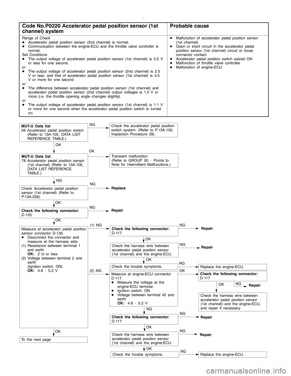
Code No.P0220 Accelerator pedal position sensor (1st
channel) systemProbable cause
Range of Check
DAcceleratorpedal positionsensor (2nd channel) is normal.
DCommunication between the engine-ECU and the throttle valve controller is
normal.
Set Conditions
DThe output voltage of accelerator pedal positionsensor (1st channel) is 0.2 V
or less for one second.
or
DThe output voltage of accelerator pedal positionsensor (2nd channel) is 2.5
V or less, and that of acceleratorpedal positionsensor (1st channel) is 4.5
V or more for one second
or
DThe difference between accelerator pedal positionsensor (1st channel) and
accelerator pedal positionsensor (2nd channel) output voltages is 1.0 V or
more (i.e. the throttle opening anglechanges slightly).
or
DThe output voltage of accelerator pedal positionsensor (1st channel) is 1.1 V
or more for one second when the acceleratorpedal positionswitch is turned
on.DMalfunction of accelerator pedal positionsensor
(1st channel)
DOpen or short circuit in the acceleratorpedal
position sensor (1st channel) circuit or loose
connector contact
DAcceleratorpedal positionswitch seized ON
DMalfunction of throttle valve controller
DMalfunction of engine-ECU
OK
Check the harness wire between
accelerator pedal positionsensor
(1st channel) and the engine-ECU,
and repair if necessary.
NG
Check Acceleratorpedal position
sensor (1st channel) (Refer to
P.13A-229).NG
Replace
OK
Check the trouble symptoms.NGReplace the engine-ECU.(2) NGMeasure at engine-ECU connector
D-117.
DMeasure the voltage at the
engine-ECU terminal.
DIgnition switch: ON
DVoltage between terminal 42 and
earth
OK:
4.8 - 5.2 VOK
OK
MUT-
IIData list
78 Acceleratorpedal positionsensor
(1st channel) (Refer to 13A-105,
DATA LIST REFERENCE
TABLE.)OKTransient malfunction
(Refer to GROUP 00 - Points to
Note for Intermittent Malfunctions.)
OK
Check the trouble symptoms.NGReplace the engine-ECU.
MUT-
IIData list
26 Acceleratorpedal positionswitch
(Refer to 13A-105, DATA LIST
REFERENCE TABLE.)NGCheck the acceleratorpedal position
switch system. (Refer to P.13A-100,
Inspection Procedure 28).
OK
Measure at accelerator pedal position
sensor connector D-135.
DDisconnect the connector and
measure at the harness side.
(1) Resistance between terminal 1
and earth
OK:
2Wor less
(2) Voltage between terminal 2 and
earth
(Ignition switch: ON)
OK:
4.8 - 5.2 V(1) NGCheck the following connector:
D-117NGRepair
NG
Repair
NG
Check the following connector:
D-117NG
Repair
OK
Check the following connector:
D-135NG
Repair
OK
Check the harness wire between
accelerator pedal positionsensor
(1st channel) and the engine-ECU.NG
Repair
OK
Check the harness wire between
accelerator pedal positionsensor
(1st channel) and the engine-ECU.NG
RepairOK
To the nextpage
Check the following connector:
D-117
OK
www.WorkshopManuals.co.uk
Purchased from www.WorkshopManuals.co.uk
Page 268 of 1839
GDI -Troubleshooting
OK
Check the harness wire between the
engine-ECU and the intermediate
connector.NG
Repair
OK
Check the following connector:
D-116NG
Repair
OK
Check the harness wire between the
ignition coil connector for a defective
cylinder and the intermediate
connector.NG
Repair
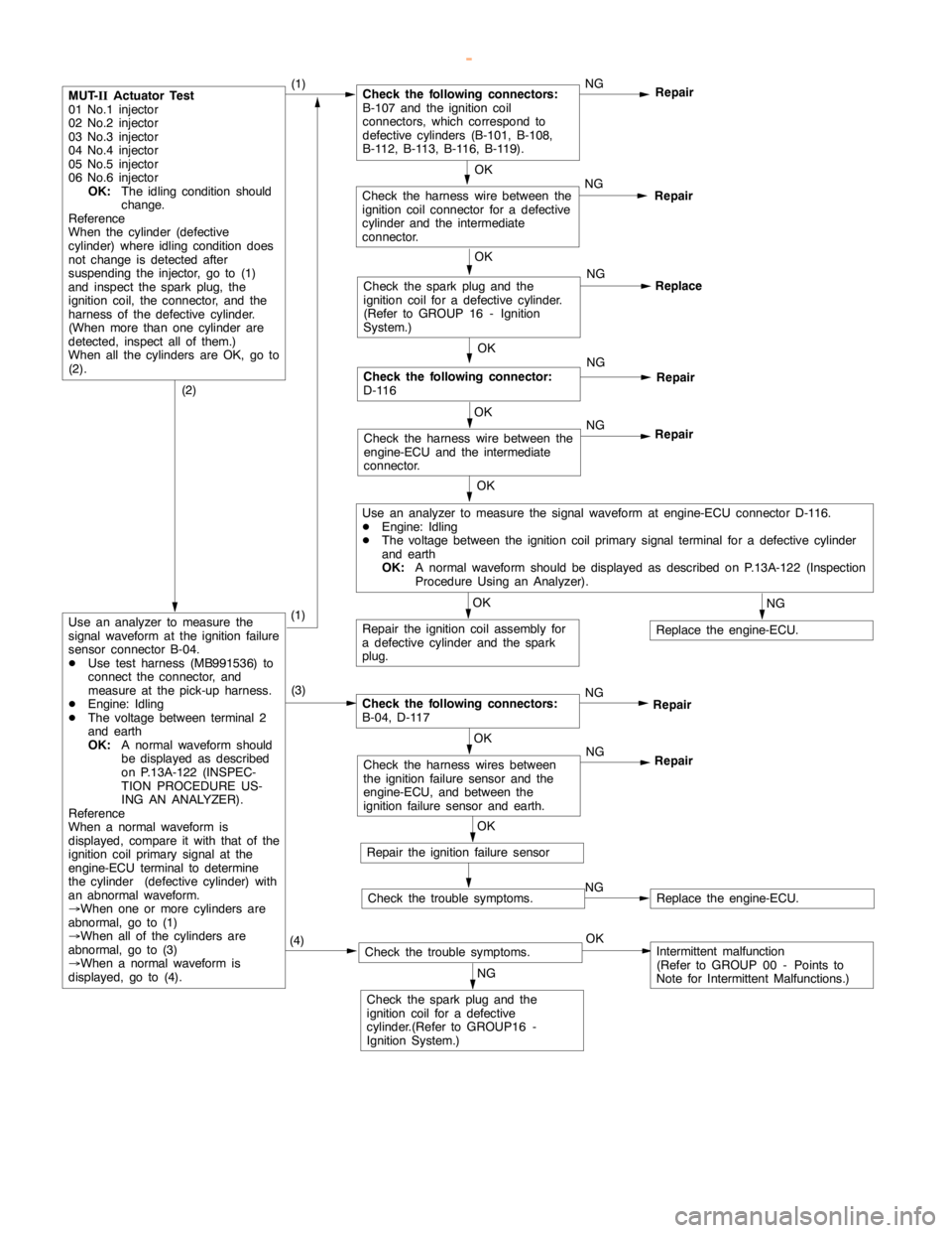
MUT-
IIActuator Test
01 No.1 injector
02 No.2 injector
03 No.3 injector
04 No.4 injector
05 No.5 injector
06 No.6 injector
OK:
The idling condition should
change.
Reference
When the cylinder (defective
cylinder) whereidling conditiondoes
not change is detected after
suspending the injector, go to (1)
and inspect the spark plug, the
ignition coil, the connector, and the
harness of the defective cylinder.
(When more than one cylinder are
detected, inspect all of them.)
When all the cylinders are OK, go to
(2).(1)Check the following connectors:
B-107 and the ignition coil
connectors, which correspond to
defective cylinders (B-101, B-108,
B-112, B-113, B-116, B-119).NG
Repair
OK
Check the sparkplug and the
ignition coil for a defective cylinder.
(Refer to GROUP 16 - Ignition
System.)NG
Replace
OK
Use an analyzer to measure the signal waveform at engine-ECU connector D-116.
DEngine: Idling
DThe voltage between the ignition coil primary signal terminal for a defective cylinder
and earth
OK:
A normal waveform should be displayed as described on P.13A-122 (Inspection
Procedure Using an Analyzer).
OK
Repair the ignition coil assembly for
a defective cylinder and the spark
plug.
NG
Replace the engine-ECU.
(2)
Use an analyzer to measure the
signal waveform at the ignition failure
sensor connector B-04.
DUse test harness (MB991536) to
connect the connector, and
measure at the pick-up harness.
DEngine: Idling
DThe voltage between terminal 2
and earth
OK:
A normal waveform should
be displayed as described
on P.13A-122 (INSPEC-
TION PROCEDURE US-
ING AN ANALYZER).
Reference
When a normal waveform is
displayed, compare it with that of the
ignition coil primary signal at the
engine-ECU terminal to determine
the cylinder (defective cylinder) with
an abnormal waveform.
®When one or more cylinders are
abnormal, go to (1)
®When all of the cylinders are
abnormal, go to (3)
®When a normal waveform is
displayed, go to (4).(3)
Check the following connectors:
B-04, D-117NG
Repair
OK
Check the harness wires between
the ignition failure sensor and the
engine-ECU, and between the
ignition failure sensor and earth.NG
Repair
OK
Repair the ignition failure sensor
Check the trouble symptoms.NGReplace the engine-ECU.
(4)Check the trouble symptoms.OKIntermittent malfunction
(Refer to GROUP 00 - Points to
Note for Intermittent Malfunctions.)
NG
Check the sparkplug and the
ignition coil for a defective
cylinder.(Refer to GROUP16 -
Ignition System.)
(1)
www.WorkshopManuals.co.uk
Purchased from www.WorkshopManuals.co.uk
Page 271 of 1839
GDI -Troubleshooting
OK
Check the harness wire between the
crankanglesensor and the
engine-ECU, and repair if necessary.
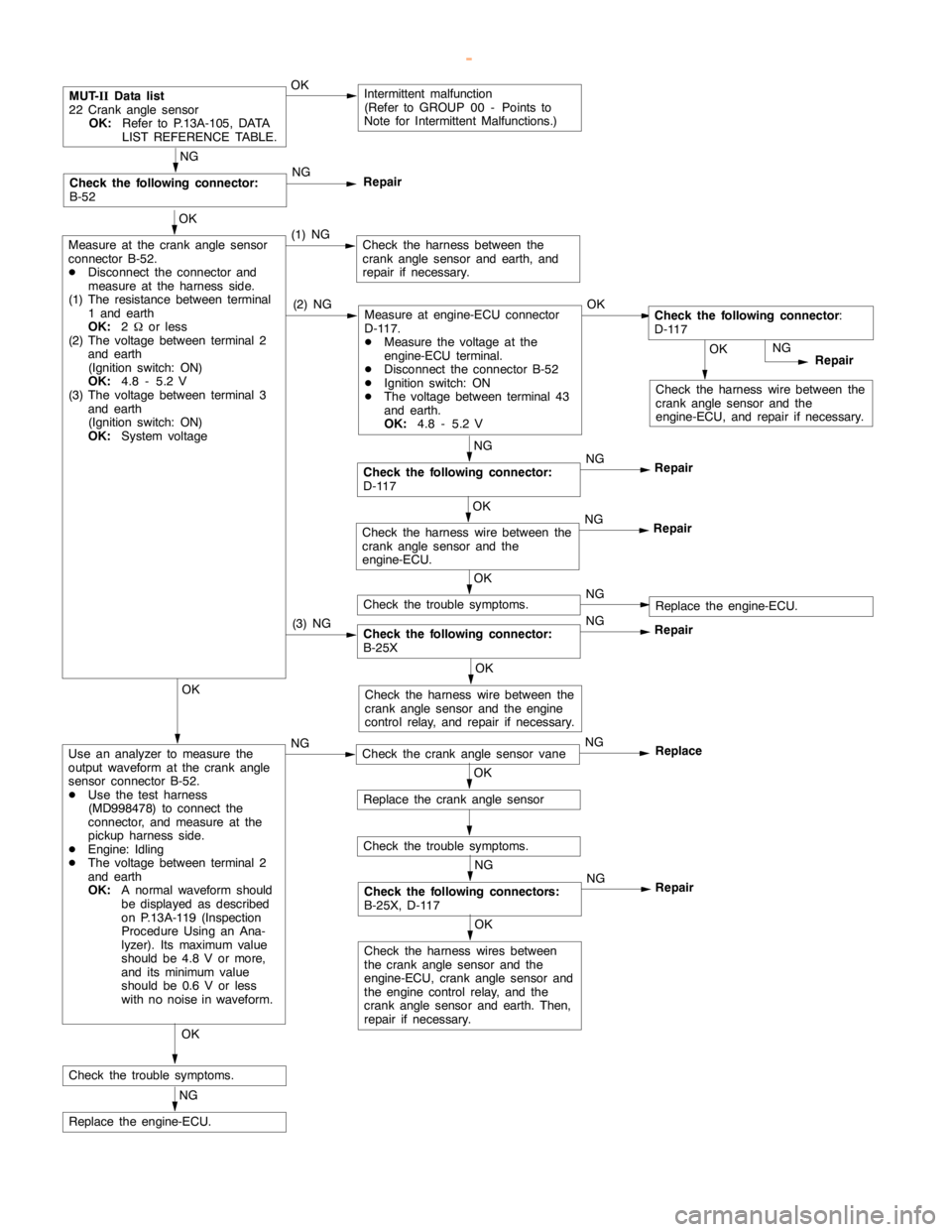
MUT-
IIData list
22 Crankanglesensor
OK:
Refer to P.13A-105, DATA
LIST REFERENCE TABLE.OKIntermittent malfunction
(Refer to GROUP 00 - Points to
Note for Intermittent Malfunctions.)
OK
Measure at the crankanglesensor
connector B-52.
DDisconnect the connector and
measure at the harness side.
(1) The resistance between terminal
1 and earth
OK:
2Wor less
(2) The voltage between terminal 2
and earth
(Ignition switch: ON)
OK:
4.8 - 5.2 V
(3) The voltage between terminal 3
and earth
(Ignition switch: ON)
OK:
System voltage(1) NGCheck the harness between the
crankanglesensor and earth, and
repair if necessary.
NG
Repair
NG
Check the following connector:
D-117NG
Repair
NG
Check the following connector:
B-52NG
Repair
(2) NGMeasure at engine-ECU connector
D-117.
DMeasure the voltage at the
engine-ECU terminal.
DDisconnect the connector B-52
DIgnition switch: ON
DThe voltage between terminal 43
and earth.
OK:
4.8 - 5.2 VOKCheck the following connector
:
D-117
Check the following connector:
B-25XNG
Repair
OK
Check the harness wire between the
crankanglesensor and the
engine-ECU.NG
Repair
OK
Check the trouble symptoms.NGReplace the engine-ECU.
(3) NG
OK
Check the harness wire between the
crankanglesensor and theengine
control relay, and repair if necessary.OK
Use an analyzer to measure the
output waveform at the crankangle
sensor connector B-52.
DUse the test harness
(MD998478) to connect the
connector, and measure at the
pickup harness side.
DEngine: Idling
DThe voltage between terminal 2
and earth
OK:
A normal waveform should
be displayed as described
on P.13A-119 (Inspection
Procedure Using an Ana-
lyzer). Its maximum value
should be 4.8 V or more,
and its minimumvalue
should be 0.6 V or less
with no noise in waveform.NGCheck the crankanglesensor vaneNG
Replace
OK
Replace the crankanglesensor
Check the trouble symptoms.
NG
Check the following connectors:
B-25X, D-117NG
Repair
OK
Check the harness wires between
the crankanglesensor and the
engine-ECU, crankanglesensor and
the engine controlrelay, and the
crankanglesensor and earth. Then,
repair if necessary.
OK
Check the trouble symptoms.
NG
Replace the engine-ECU.
www.WorkshopManuals.co.uk
Purchased from www.WorkshopManuals.co.uk