inspection procedure 13 MITSUBISHI MONTERO 2000 Service Repair Manual
[x] Cancel search | Manufacturer: MITSUBISHI, Model Year: 2000, Model line: MONTERO, Model: MITSUBISHI MONTERO 2000Pages: 1839, PDF Size: 29.19 MB
Page 1737 of 1839
SWS -Troubleshooting54B-51
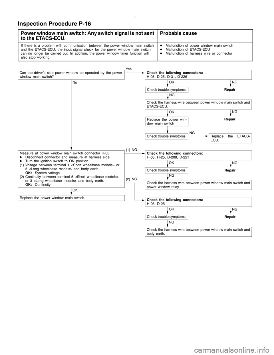
Inspection Procedure P-16
Power window main switch: Any switch signal is not sent
to the ETACS-ECU.Probable cause
If there is a problem with communication between the power windowmainswitch
and the ETACS-ECU, the input signal check for the power windowmainswitch
can no longer be carried out. In addition, the power window timer function will
also stop working.DMalfunction of power windowmainswitch
DMalfunction of ETACS-ECU
DMalfunction of harness wire or connector
Ye s
NG
Repair
NG
No
(1) NG
NG
Repair
NG
Check the harness wire between power windowmainswitch and
power window relay.
OK
Replace the power windowmainswitch.
NG
Repair
NG
Check the harness wire between power windowmainswitch and
body earth.
NG
Repair
Check trouble symptoms.NGReplace the ETACS-
ECU.
OK
Check trouble symptoms.
(2) NG
Check the following connectors:
H-05, D-25
OK
Check trouble symptoms.
Check the following connectors:
H-05, H-25, D-208, D-221Measure at power windowmainswitch connector H-05.
DDisconnect connector and measure at harness side.
DTurn the ignition switch to ON position.
(1) Voltage between terminal 1
5
OK:System voltage
(2) Continuity between terminal 5
or 3
OK:Continuity
OK
Replace the power win-
dow mainswitch
Check the harness wire between power windowmainswitch and
ETACS-ECU.
OK
Check trouble symptoms.
Check the following connectors:
H-05, D-25, D-31, D-226Can the driver’s side power window be operated by the power
window mainswitch?
www.WorkshopManuals.co.uk
Purchased from www.WorkshopManuals.co.uk
Page 1738 of 1839
SWS -Troubleshooting54B-52
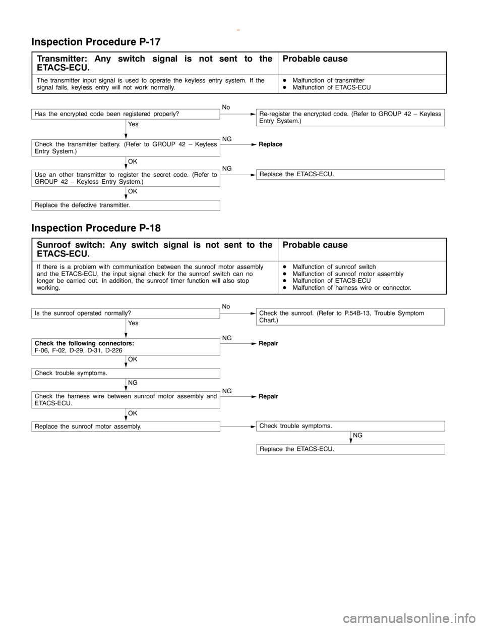
Inspection Procedure P-17
Transmitter: Any switch signal is not sent to the
ETACS-ECU.Probable cause
The transmitter input signal is used to operate the keyless entry system. If the
signal fails, keyless entry will not work normally.DMalfunction of transmitter
DMalfunction of ETACS-ECU
Ye s
NG
Replace
OK
Replace the defective transmitter.
OK
Use an other transmitter to register the secret code. (Refer to
GROUP 42 – Keyless Entry System.)NGReplace the ETACS-ECU.
Check the transmitter battery. (Refer to GROUP 42 – Keyless
Entry System.)
Has the encrypted codebeen registered properly?NoRe-register the encrypted code. (Refer to GROUP 42 – Keyless
Entry System.)
Inspection Procedure P-18
Sunroof switch: Any switch signal is not sent to the
ETACS-ECU.Probable cause
If there is a problem with communication between the sunroof motor assembly
and the ETACS-ECU, the input signal check for the sunroof switch can no
longer be carried out. In addition, the sunroof timer function will also stop
working.DMalfunction of sunroof switch
DMalfunction of sunroof motor assembly
DMalfunction of ETACS-ECU
DMalfunction of harness wire or connector.
Ye s
NG
Repair
NG
Replace the ETACS-ECU.
OK
Replace the sunroof motor assembly.Check trouble symptoms.
NG
Check the harness wire between sunroof motor assembly and
ETACS-ECU.NG
Repair
OK
Check trouble symptoms.
Check the following connectors:
F-06, F-02, D-29, D-31, D-226
Is the sunroof operated normally?NoCheck the sunroof. (Refer to P.54B-13, Trouble Symptom
Chart.)
www.WorkshopManuals.co.uk
Purchased from www.WorkshopManuals.co.uk
Page 1739 of 1839
SWS -Troubleshooting54B-53
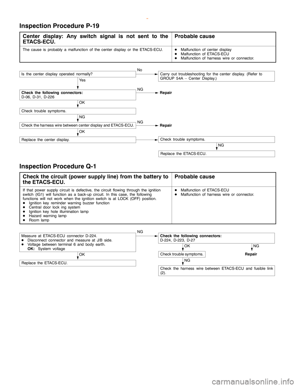
Inspection Procedure P-19
Center display: Any switch signal is not sent to the
ETACS-ECU.Probable cause
The cause is probably a malfunction of the center display or the ETACS-ECU.DMalfunction of center display
DMalfunction of ETACS-ECU
DMalfunction of harness wire or connector.
Ye s
NG
Repair
NG
Replace the ETACS-ECU.
OK
Replace the center display.Check trouble symptoms.
NG
Check the harness wire between center display and ETACS-ECU.NG
Repair
OK
Check trouble symptoms.
Check the following connectors:
D-06, D-31, D-226
Is the center display operated normally?NoCarry out troubleshooting for the center display. (Refer to
GROUP 54A – Center Display.)
Inspection Procedure Q-1
Check the circuit (power supply line) from the battery to
the ETACS-ECU.Probable cause
If that power supply circuit is defective, the circuit flowing through the ignition
switch (IG1) will function as a back-up circuit. In this case, the following
functions will not work when the ignition switch is at LOCK (OFF) position.
DIgnition key reminder warning buzzer function
DCentral door lock ing system
DIgnition key hole illumination lamp
DHazard warninglamp
DRoom lampDMalfunction of ETACS-ECU
DMalfunction of harness wire or connector.
NG
NG
Repair
NG
Check the harness wire between ETACS-ECU and fusible link
(2).
OK
Replace the ETACS-ECU.
OK
Check trouble symptoms.
Check the following connectors:
D-224, D-223, D-27Measure at ETACS-ECU connector D-224.
DDisconnect connector and measure at J/B side.
DVoltage between terminal 6 and body earth.
OK:System voltage
www.WorkshopManuals.co.uk
Purchased from www.WorkshopManuals.co.uk
Page 1807 of 1839
HEATER, AIR CONDITIONER AND VENTILATION -Troubleshooting
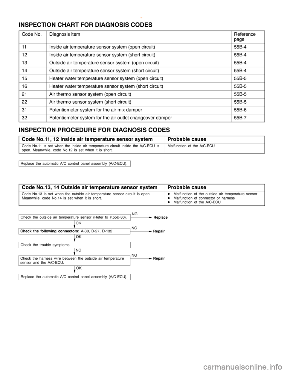
INSPECTION CHART FOR DIAGNOSIS CODES
Code No.Diagnosis itemReference
page
11Inside air temperature sensor system (open circuit)55B-4
12Inside air temperature sensor system (short circuit)55B-4
13Outside air temperature sensor system (open circuit)55B-4
14Outside air temperature sensor system (short circuit)55B-4
15Heater water temperature sensor system (open circuit)55B-5
16Heater water temperature sensor system (short circuit)55B-5
21Air thermo sensor system (open circuit)55B-5
22Air thermo sensor system (short circuit)55B-5
31Potentiometer system for the air mix damper55B-6
32Potentiometer system for the air outlet changeover damper55B-7
INSPECTION PROCEDURE FOR DIAGNOSIS CODES
Code No.11, 12 Inside air temperature sensor systemProbable cause
Code No.11 is set when the inside air temperature circuit inside the A/C-ECU is
open. Meanwhile, code No.12 is set when it is short.Malfunction of the A/C-ECU
Replace the automatic A/C control panelassembly (A/C-ECU).
Code No.13, 14 Outside air temperature sensor systemProbable cause
Code No.13 is set when the outside air temperature sensor circuit is open.
Meanwhile, code No.14 is set when it is short.DMalfunction of the outside air temperature sensor
DMalfunction of connector or harness
DMalfunction of the A/C-ECU
OK
Replace the automatic A/C control panelassembly (A/C-ECU).
NG
Check the harness wire between the outside air temperature
sensor and the A/C-ECU.NG
Repair
OK
Check the trouble symptoms.
OK
Check the following connectors:A-30, D-27, D-132NG
Repair
Check the outside air temperature sensor (Refer to P.55B-30).NG
Replace
www.WorkshopManuals.co.uk
Purchased from www.WorkshopManuals.co.uk
Page 1811 of 1839
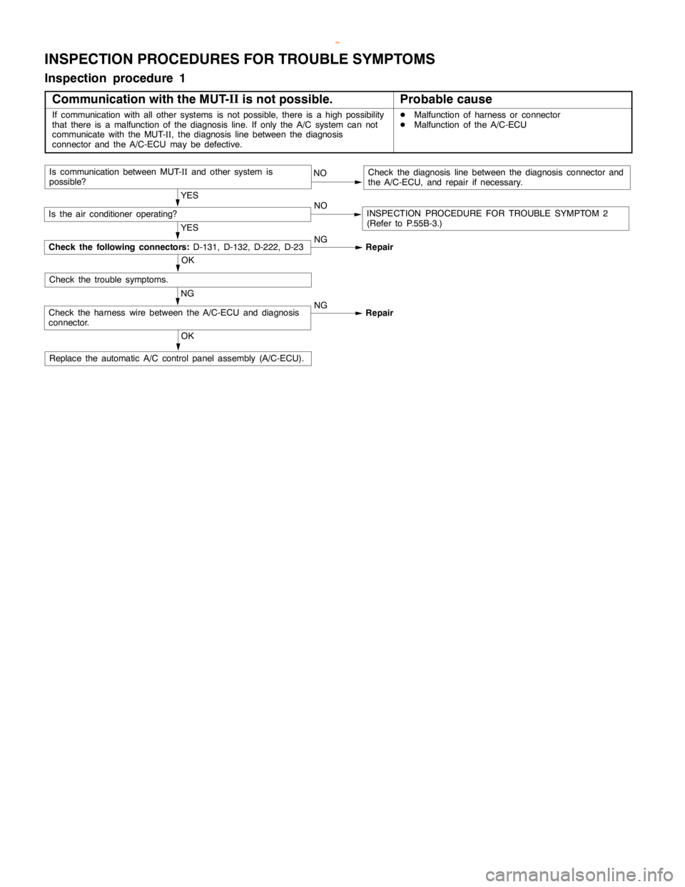
HEATER, AIR CONDITIONER AND VENTILATION -Troubleshooting
INSPECTION PROCEDURES FOR TROUBLE SYMPTOMS
Inspection procedure 1
Communication with the MUT-II
is not possible.
Probable cause
If communication with all other systems is not possible, there is ahigh possibility
that there is a malfunction of the diagnosis line. If only the A/C system can not
communicate with the MUT-
II, the diagnosis line between the diagnosis
connector and the A/C-ECU may be defective.DMalfunction of harness or connector
DMalfunction of the A/C-ECU
OK
Replace the automatic A/C control panelassembly (A/C-ECU).
NOCheck the diagnosis line between the diagnosis connector and
the A/C-ECU, and repair if necessary.
YES
NO
INSPECTION PROCEDURE FOR TROUBLE SYMPTOM 2
(Refer to P.55B-3.)
YES
NG
Repair
OK
NG
Check the harness wire between the A/C-ECU and diagnosis
connector.NG
Repair
Check the trouble symptoms.
Check the following connectors:D-131, D-132, D-222, D-23
Is the air conditioner operating?
Is communication between MUT-
IIand other system is
possible?
www.WorkshopManuals.co.uk
Purchased from www.WorkshopManuals.co.uk
Page 1812 of 1839
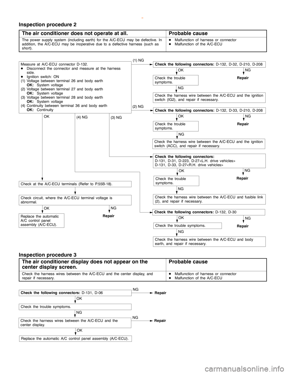
HEATER, AIR CONDITIONER AND VENTILATION -Troubleshooting
Inspection procedure 2
The air conditioner does not operate at all.
Probable cause
The power supply system (including earth) for the A/C-ECU may be defective. In
addition, the A/C-ECU may be inoperative due to a defective harness (such as
short).DMalfunction of harness or connector
DMalfunction of the A/C-ECU
NG
Repair
NG
Check the harness wire between the A/C-ECU and the ignition
switch (IG2), and repair if necessary.
NG
Repair
NG
Check the harness wire between the A/C-ECU and the ignition
switch (ACC), and repair if necessary.
NG
Repair
NG
Check the harness wire between the A/C-ECU and fusible link
(2), and repair if necessary.
NG
Repair
NG
Check the harness wire between the A/C-ECU and body
earth, and repair if necessary.
OK
Replace the automatic
A/C control panel
assembly (A/C-ECU).
NG
Repair
Check circuit, where the A/C-ECU terminal voltage is
abnormal.
OK
Check at the A/C-ECU terminals (Refer to P.55B-18).
OK
Check the trouble symptoms.
Check the following connectors:D-132, D-30
(4) NG
OK
Check the trouble
symptoms.
Check the following connectors:
D-131, D-31, D-223, D-27
D-131, D-33, D-27
(3) NGOK
Check the trouble
symptoms.
Check the following connectors:D-132, D-33, D-210, D-208(2) NG
OK
Check the trouble
symptoms.
Measure at A/C-ECU connector D-132.
DDisconnect the connector and measure at the harness
side.
DIgnition switch: ON
(1) Voltage between terminal 26 and body earth
OK:System voltage
(2) Voltage between terminal 27 and body earth
OK:System voltage
(3) Voltage between terminal 28 and body earth
OK:System voltage
(4) Continuity between terminal 36 and body earth
OK:Continuity(1) NGCheck the following connectors:D-132, D-32, D-210, D-208
Inspection procedure 3
The air conditioner display does not appear on the
center display screen.
Probable cause
Check the harness wires between the A/C-ECU and the center display, and
repair if necessary.DMalfunction of harness or connector
DMalfunction of the A/C-ECU
OK
Replace the automatic A/C control panelassembly (A/C-ECU).
NG
Check the harness wires between the A/C-ECU and the
center display.NG
Repair
OK
Check the trouble symptoms.
Check the following connectors:D-131, D-06NG
Repair
www.WorkshopManuals.co.uk
Purchased from www.WorkshopManuals.co.uk
Page 1813 of 1839
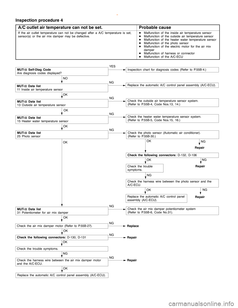
HEATER, AIR CONDITIONER AND VENTILATION -Troubleshooting
Inspection procedure 4
A/C outlet air temperature can not be set.
Probable cause
If the air outlet temperature can not be changed after a A/C temperature is set,
sensor(s) or the air mix damper may be defective.DMalfunction of the inside air temperature sensor
DMalfunction of the outside air temperature sensor
DMalfunction of the heater water temperature sensor
DMalfunction of the photo sensor
DMalfunction of the electric motor for the air mix
damper
DMalfunction of harness or connector
DMalfunction of the A/C-ECU
NG
Repair
NG
Repair
OK
Replace the automatic A/C control panelassembly (A/C-ECU).
OK
MUT-
IIData list
31 Potentiometer for air mix damperNGCheck the air mix damper potentiometer system
(Refer to P.55B-6, Code No.31).
NG
Check the harness wire between the photo sensor and the
A/C-ECU.
OK
Check the trouble
symptoms.
OK
Check the following connectors:D-132, D-106
OK
MUT-
IIData list
25 Photo sensorNGCheck the photo sensor (Automatic air conditioner).
(Refer to P.55B-30.)
OK
MUT-
IIData list
15 Heater water temperature sensorNGCheck the heater water temperature sensor system.
(Refer to P.55B-5, Code Nos.15, 16.)
OK
MUT-
IIData list
13 Outside air temperature sensorNGCheck the outside air temperature sensor system.
(Refer to P.55B-4, Code Nos.13, 14.)
NO
MUT-
IIData list
11 Inside air temperature sensorNGReplace the automatic A/C control panelassembly (A/C-ECU).
MUT-
IISelf-Diag Code
Are diagnosis codes displayed?YESInspection chart for diagnosis codes (Refer to P.55B-4.)
NG
Repair OKReplace the automatic A/C control panel
assembly (A/C-ECU).
NG
Check the harness wire between the air mix damper motor
and the A/C-ECU.NG
Repair
OK
Check the trouble symptoms.
OK
Check the following connectors:D-130, D-131NG
Repair
Check the air mix damper motor (Refer to P.55B-27).NG
Replace OK
www.WorkshopManuals.co.uk
Purchased from www.WorkshopManuals.co.uk
Page 1814 of 1839
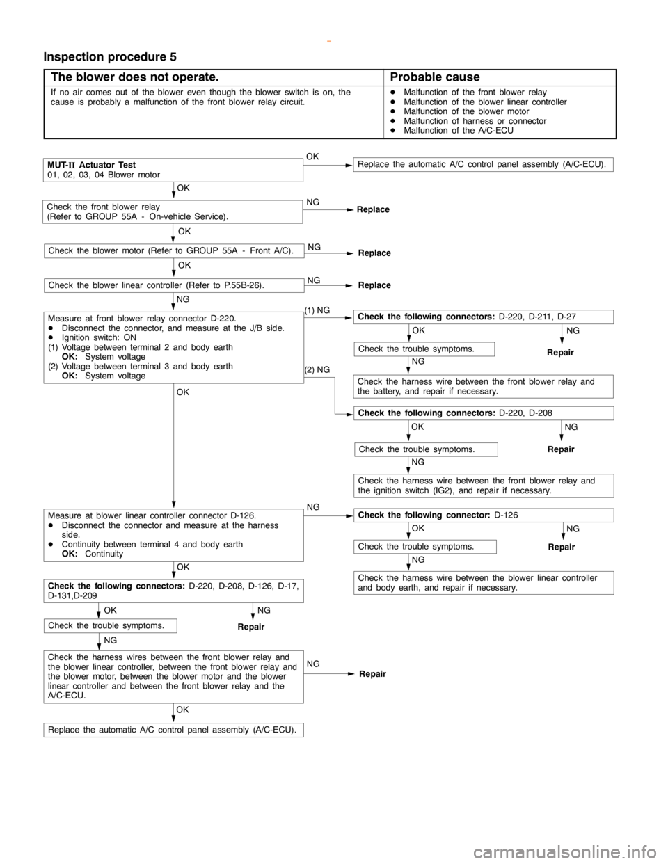
HEATER, AIR CONDITIONER AND VENTILATION -Troubleshooting
Inspection procedure 5
The blower does not operate.
Probable cause
If no air comes out of the blower even though the blower switch is on, the
cause is probably a malfunction of the front blower relay circuit.DMalfunction of the front blower relay
DMalfunction of the blower linear controller
DMalfunction of the blower motor
DMalfunction of harness or connector
DMalfunction of the A/C-ECU
NG
Repair
NG
Repair
NG
Repair
NG
Check the harness wire between the front blower relay and
the ignition switch (IG2), and repair if necessary.
NG
Check the harness wire between the front blower relay and
the battery, and repair if necessary.
NG
Repair
NG
Check the harness wire between the blower linear controller
and body earth, and repair if necessary.
OK
Replace the automatic A/C control panelassembly (A/C-ECU).
NG
Check the harness wires between the front blower relay and
the blower linear controller, between the front blower relay and
the blower motor, between the blower motor and the blower
linear controller and between the front blower relay and the
A/C-ECU.NG
Repair
OK
Check the trouble symptoms.
OK
Check the following connectors:D-220, D-208, D-126, D-17,
D-131,D-209
OK
Check the trouble symptoms.
OK
Measure at blower linear controller connector D-126.
DDisconnect the connector and measure at the harness
side.
DContinuity between terminal 4 and body earth
OK:ContinuityNGCheck the following connector:D-126
OK
Check the trouble symptoms.
Check the following connectors:D-220, D-208
(2) NG
OK
Check the trouble symptoms.
NG
Measure at front blower relay connector D-220.
DDisconnect the connector, and measure at the J/B side.
DIgnition switch: ON
(1) Voltage between terminal 2 and body earth
OK:System voltage
(2) Voltage between terminal 3 and body earth
OK:System voltage(1) NGCheck the following connectors:D-220, D-211, D-27
OK
Check the blower linear controller (Refer to P.55B-26).NG
Replace
OK
Check the blower motor (Refer to GROUP 55A - Front A/C).NG
Replace
OK
Check the front blower relay
(Refer to GROUP 55A - On-vehicle Service).NG
Replace
MUT-
IIActuator Test
01, 02, 03, 04 Blower motorOKReplace the automatic A/C control panelassembly (A/C-ECU).
www.WorkshopManuals.co.uk
Purchased from www.WorkshopManuals.co.uk
Page 1815 of 1839
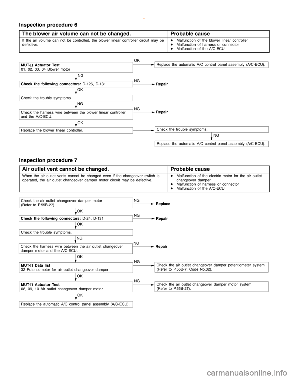
HEATER, AIR CONDITIONER AND VENTILATION -Troubleshooting
Inspection procedure 6
The blower air volume can not be changed.
Probable cause
If the air volume can not be controlled, the blower linear controller circuit may be
defective.DMalfunction of the blower linear controller
DMalfunction of harness or connector
DMalfunction of the A/C-ECU
NG
Replace the automatic A/C control panelassembly (A/C-ECU).
OK
Replace the blower linear controller.Check the trouble symptoms.
MUT-
IIActuator Test
01, 02, 03, 04 Blower motorOKReplace the automatic A/C control panelassembly (A/C-ECU).
NG
Check the following connectors:D-126, D-131NG
Repair
OK
Check the trouble symptoms.
NG
Check the harness wire between the blower linear controller
and the A/C-ECU.NG
Repair
Inspection procedure 7
Air outlet vent cannot be changed.
Probable cause
When the air outlet vents cannot be changed even if the changeover switch is
operated, the air outlet changeover damper motor circuit may be defective.DMalfunction of the electric motor for the air outlet
changeover damper
DMalfunction of harness or connector
DMalfunction of the A/C-ECU
OK
Replace the automatic A/C control panelassembly (A/C-ECU).
OK
MUT-
IIActuator Test
08, 09, 10 Air outlet changeover damper motorNGCheck the air outlet changeover damper motor system
(Refer to P.55B-27).
MUT-
IIData list
32 Potentiometer for air outlet changeover damperNGCheck the air outlet changeover damper potentiometer system
(Refer to P.55B-7, Code No.32).
OK
NG
Check the harness wire between the air outlet changeover
damper motor and the A/C-ECU.NG
Repair
OK
Check the trouble symptoms.
OK
Check the following connectors:D-24, D-131NG
Repair
Check the air outlet changeover damper motor
(Refer to P.55B-27).NG
Replace
www.WorkshopManuals.co.uk
Purchased from www.WorkshopManuals.co.uk
Page 1816 of 1839
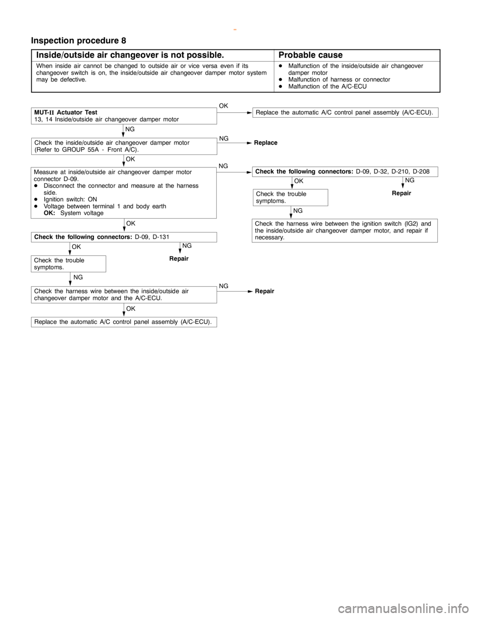
HEATER, AIR CONDITIONER AND VENTILATION -Troubleshooting
Inspection procedure 8
Inside/outside air changeover is not possible.
Probable cause
When inside air cannot be changed to outside air or vice versa even if its
changeover switch is on, the inside/outside air changeover damper motor system
may be defective.DMalfunction of the inside/outside air changeover
damper motor
DMalfunction of harness or connector
DMalfunction of the A/C-ECU
NG
Repair
NG
Check the harness wire between the ignition switch (IG2) and
the inside/outside air changeover damper motor, and repair if
necessary.
NG
Repair
OK
Replace the automatic A/C control panelassembly (A/C-ECU).
NG
Check the harness wire between the inside/outside air
changeover damper motor and the A/C-ECU.NG
Repair
OK
Check the trouble
symptoms.
OK
Check the following connectors:D-09, D-131
OK
Check the trouble
symptoms.
OK
Measure at inside/outside air changeover damper motor
connector D-09.
DDisconnect the connector and measure at the harness
side.
DIgnition switch: ON
DVoltage between terminal 1 and body earth
OK:System voltageNGCheck the following connectors:D-09, D-32, D-210, D-208
NG
Check the inside/outside air changeover damper motor
(Refer to GROUP 55A - Front A/C).NG
Replace
MUT-
IIActuator Test
13, 14 Inside/outside air changeover damper motorOKReplace the automatic A/C control panelassembly (A/C-ECU).
www.WorkshopManuals.co.uk
Purchased from www.WorkshopManuals.co.uk