MITSUBISHI MONTERO 2000 Service Repair Manual
Manufacturer: MITSUBISHI, Model Year: 2000, Model line: MONTERO, Model: MITSUBISHI MONTERO 2000Pages: 1839, PDF Size: 29.19 MB
Page 251 of 1839
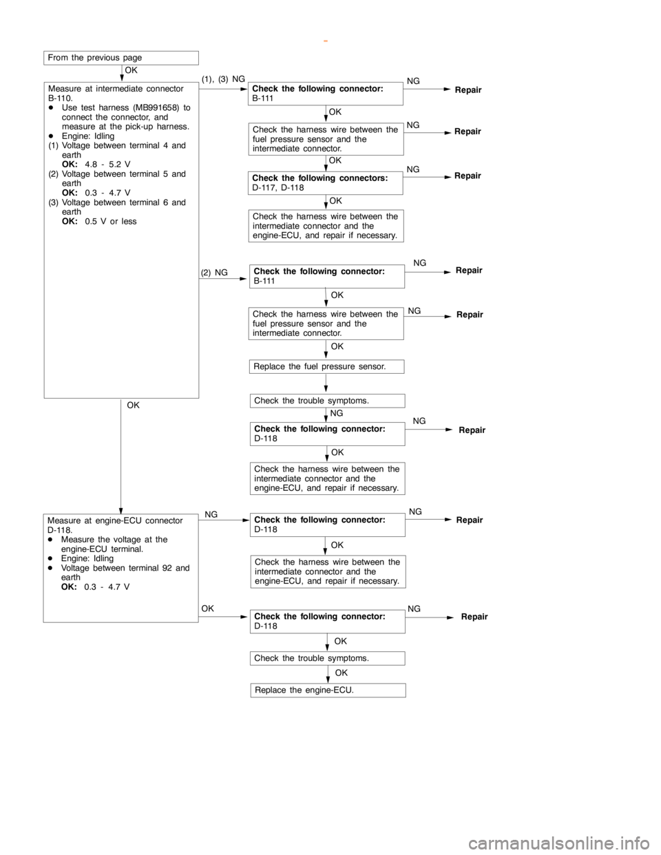
GDI -Troubleshooting
NG
(2) NGCheck the following connector:
B - 111NG
Repair
OK
Measure at intermediate connector
B-110.
DUse test harness (MB991658) to
connect the connector, and
measure at the pick-up harness.
DEngine: Idling
(1) Voltage between terminal 4 and
earth
OK:
4.8 - 5.2 V
(2) Voltage between terminal 5 and
earth
OK:
0.3 - 4.7 V
(3) Voltage between terminal 6 and
earth
OK:
0.5 V or less(1), (3) NGCheck the following connector:
B - 111
OK
Check the following connectors:
D-117, D-118NG
Repair
OK
Check the harness wire between the
fuel pressure sensor and the
intermediate connector.NG
Repair
From the previouspage
OK
Check the harness wire between the
intermediate connector and the
engine-ECU, and repair if necessary.
OK
Check the harness wire between the
fuel pressure sensor and the
intermediate connector.NG
Repair
OK
Replace the fuel pressure sensor.
Check the trouble symptoms.
Check the following connector:
D-118NG
Repair
NG
Check the harness wire between the
intermediate connector and the
engine-ECU, and repair if necessary.
OK
Measure at engine-ECU connector
D-118.
DMeasure the voltage at the
engine-ECU terminal.
DEngine: Idling
DVoltage between terminal 92 and
earth
OK:
0.3 - 4.7 VNGCheck the following connector:
D-118NG
Repair
OK
Check the harness wire between the
intermediate connector and the
engine-ECU, and repair if necessary.
OKCheck the following connector:
D-118NG
Repair
OK
Check the trouble symptoms.
OK
Replace the engine-ECU.OKRepair
www.WorkshopManuals.co.uk
Purchased from www.WorkshopManuals.co.uk
Page 252 of 1839
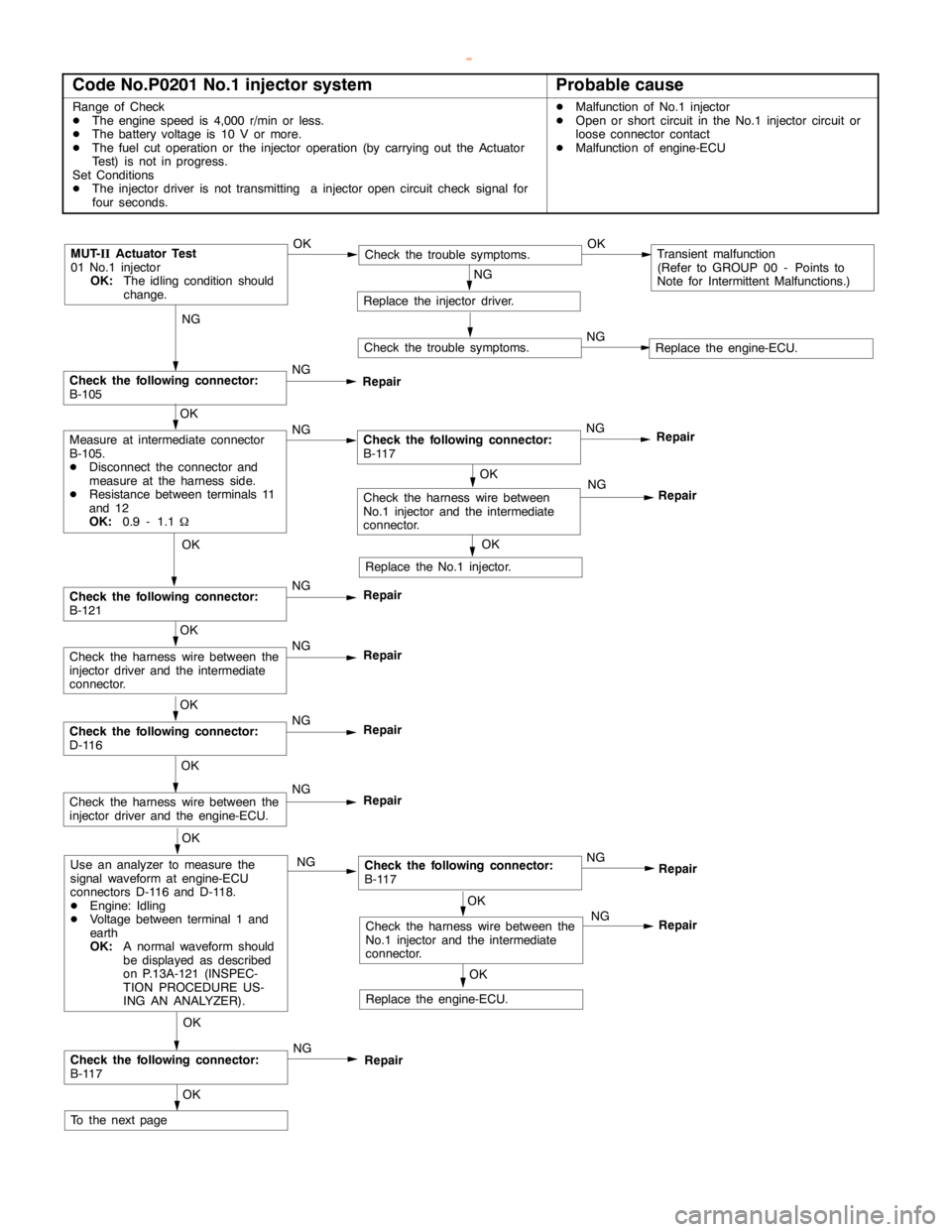
GDI -Troubleshooting
Code No.P0201 No.1 injector systemProbable cause
Range of Check
DThe enginespeed is 4,000 r/min or less.
DThe battery voltage is 10 V or more.
DThe fuel cut operation or the injector operation (by carrying out the Actuator
Test) is not in progress.
Set Conditions
DThe injector driver is not transmitting a injectoropencircuit check signal for
four seconds.DMalfunction of No.1 injector
DOpen or short circuit in the No.1 injector circuit or
loose connector contact
DMalfunction of engine-ECU
NG
Check the following connector:
B-105NG
Repair
OK
NG
Repair
MUT-
IIActuator Test
01 No.1 injector
OK:
The idling condition should
change.OKCheck the trouble symptoms.OKTransient malfunction
(Refer to GROUP 00 - Points to
Note for Intermittent Malfunctions.)
NG
Replace the injector driver.
Check the trouble symptoms.NGReplace the engine-ECU.
OK
Measure at intermediate connector
B-105.
DDisconnect the connector and
measure at the harness side.
DResistance between terminals 11
and 12
OK:
0.9 - 1.1WNGCheck the following connector:
B-117NG
Repair
OK
Replace the No.1 injector.
OK
Check the following connector:
B-121NG
Repair
OK
Check the harness wire between the
injector driver and the intermediate
connector.NG
Repair
OK
Check the following connector:
D-116NG
Repair
OK
Check the harness wire between the
injector driver and the engine-ECU.NG
Repair
OK
Use an analyzer to measure the
signal waveform at engine-ECU
connectors D-116 and D-118.
DEngine: Idling
DVoltage between terminal 1 and
earth
OK:
A normal waveform should
be displayed as described
on P.13A-121 (INSPEC-
TION PROCEDURE US-
ING AN ANALYZER).NGCheck the following connector:
B-117
OK
Check the following connector:
B-117NG
Repair
OK
To the nextpageNG
OK
OK
Check the harness wire between the
No.1 injector and the intermediate
connector.NG
Replace the engine-ECU.
Repair
Repair
Check the harness wire between
No.1 injector and the intermediate
connector.
www.WorkshopManuals.co.uk
Purchased from www.WorkshopManuals.co.uk
Page 253 of 1839

GDI -Troubleshooting
OK
Check the harness wire between
No.1 injector and the intermediate
connector.NG
Repair
From the previouspage
OK
Check the trouble symptoms.NGReplace the injector driver.
Replace the No.1 injector.
NG
www.WorkshopManuals.co.uk
Purchased from www.WorkshopManuals.co.uk
Page 254 of 1839
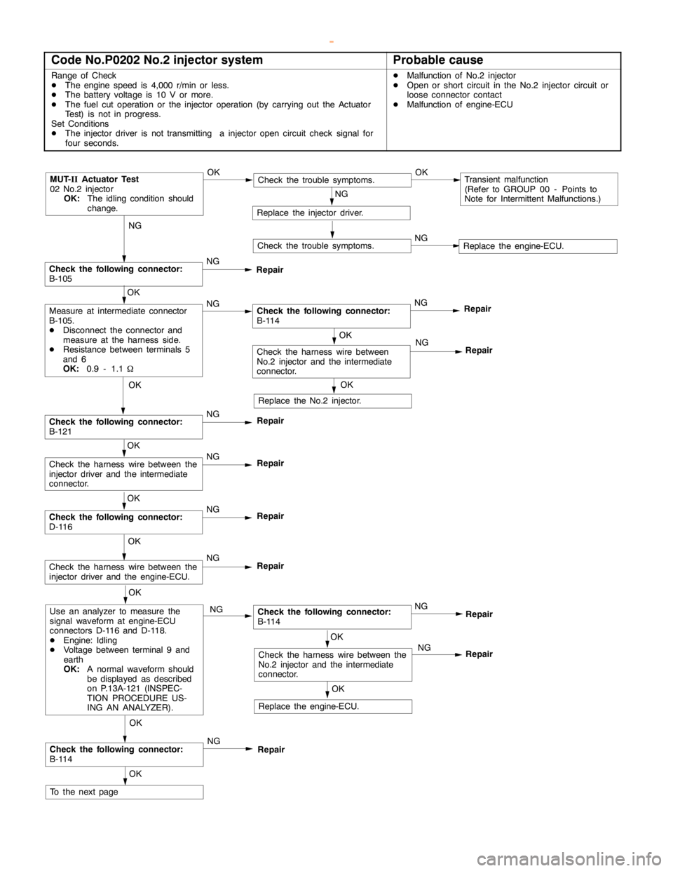
GDI -Troubleshooting
Code No.P0202 No.2 injector systemProbable cause
Range of Check
DThe enginespeed is 4,000 r/min or less.
DThe battery voltage is 10 V or more.
DThe fuel cut operation or the injector operation (by carrying out the Actuator
Test) is not in progress.
Set Conditions
DThe injector driver is not transmitting a injectoropencircuit check signal for
four seconds.DMalfunction of No.2 injector
DOpen or short circuit in the No.2 injector circuit or
loose connector contact
DMalfunction of engine-ECU
NG
Check the following connector:
B-105NG
Repair
OK
NG
Repair
MUT-
IIActuator Test
02 No.2 injector
OK:
The idling condition should
change.OKCheck the trouble symptoms.OKTransient malfunction
(Refer to GROUP 00 - Points to
Note for Intermittent Malfunctions.)
NG
Replace the injector driver.
Check the trouble symptoms.NGReplace the engine-ECU.
OK
Measure at intermediate connector
B-105.
DDisconnect the connector and
measure at the harness side.
DResistance between terminals 5
and 6
OK:
0.9 - 1.1WNGCheck the following connector:
B-114NG
Repair
OK
Replace the No.2 injector.
OK
Check the following connector:
B-121NG
Repair
OK
Check the harness wire between the
injector driver and the intermediate
connector.NG
Repair
OK
Check the following connector:
D-116NG
Repair
OK
Check the harness wire between the
injector driver and the engine-ECU.NG
Repair
OK
Use an analyzer to measure the
signal waveform at engine-ECU
connectors D-116 and D-118.
DEngine: Idling
DVoltage between terminal 9 and
earth
OK:
A normal waveform should
be displayed as described
on P.13A-121 (INSPEC-
TION PROCEDURE US-
ING AN ANALYZER).NGCheck the following connector:
B-114
OK
Check the following connector:
B-114NG
Repair
OK
To the nextpageNG
OK
OK
Check the harness wire between the
No.2 injector and the intermediate
connector.NG
Replace the engine-ECU.
Repair
Repair
Check the harness wire between
No.2 injector and the intermediate
connector.
www.WorkshopManuals.co.uk
Purchased from www.WorkshopManuals.co.uk
Page 255 of 1839

GDI -Troubleshooting
OK
Check the harness wire between
No.2 injector and the intermediate
connector.NG
Repair
From the previouspage
OK
Check the trouble symptoms.NGReplace the injector driver.
Replace the No.2 injector.
www.WorkshopManuals.co.uk
Purchased from www.WorkshopManuals.co.uk
Page 256 of 1839
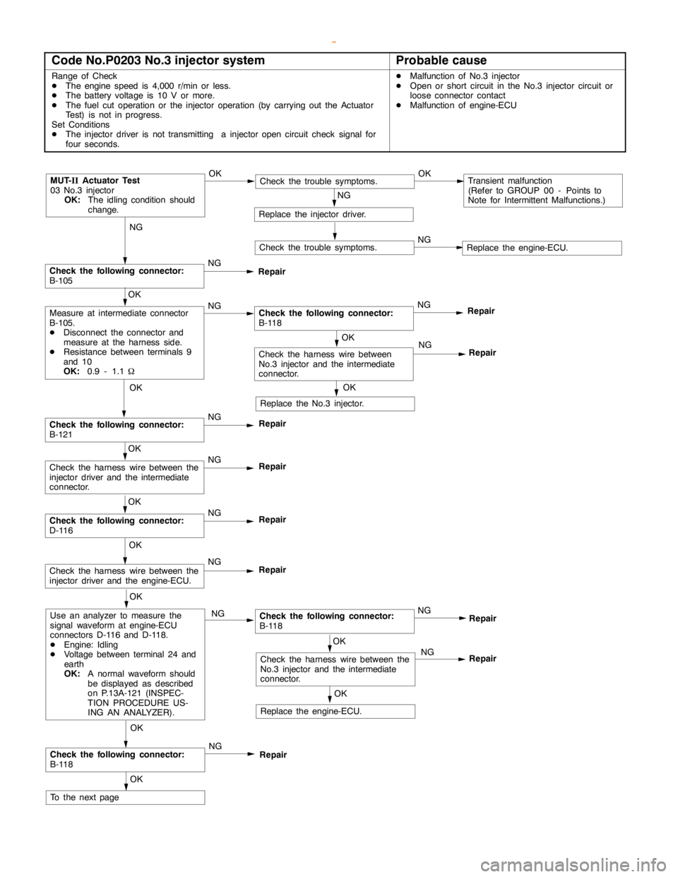
GDI -Troubleshooting
Code No.P0203 No.3 injector systemProbable cause
Range of Check
DThe enginespeed is 4,000 r/min or less.
DThe battery voltage is 10 V or more.
DThe fuel cut operation or the injector operation (by carrying out the Actuator
Test) is not in progress.
Set Conditions
DThe injector driver is not transmitting a injectoropencircuit check signal for
four seconds.DMalfunction of No.3 injector
DOpen or short circuit in the No.3 injector circuit or
loose connector contact
DMalfunction of engine-ECU
NG
Check the following connector:
B-105NG
Repair
OK
NG
Repair
MUT-
IIActuator Test
03 No.3 injector
OK:
The idling condition should
change.OKCheck the trouble symptoms.OKTransient malfunction
(Refer to GROUP 00 - Points to
Note for Intermittent Malfunctions.)
NG
Replace the injector driver.
Check the trouble symptoms.NGReplace the engine-ECU.
OK
Measure at intermediate connector
B-105.
DDisconnect the connector and
measure at the harness side.
DResistance between terminals 9
and 10
OK:
0.9 - 1.1WNGCheck the following connector:
B-118NG
Repair
OK
Replace the No.3 injector.
OK
Check the following connector:
B-121NG
Repair
OK
Check the harness wire between the
injector driver and the intermediate
connector.NG
Repair
OK
Check the following connector:
D-116NG
Repair
OK
Check the harness wire between the
injector driver and the engine-ECU.NG
Repair
OK
Use an analyzer to measure the
signal waveform at engine-ECU
connectors D-116 and D-118.
DEngine: Idling
DVoltage between terminal 24 and
earth
OK:
A normal waveform should
be displayed as described
on P.13A-121 (INSPEC-
TION PROCEDURE US-
ING AN ANALYZER).NGCheck the following connector:
B-118
OK
Check the following connector:
B-118NG
Repair
OK
To the nextpageNG
OK
OK
Check the harness wire between the
No.3 injector and the intermediate
connector.NG
Replace the engine-ECU.
Repair
Repair
Check the harness wire between
No.3 injector and the intermediate
connector.
www.WorkshopManuals.co.uk
Purchased from www.WorkshopManuals.co.uk
Page 257 of 1839

GDI -Troubleshooting
OK
Check the harness wire between
No.3 injector and the intermediate
connector.NG
Repair
From the previouspage
OK
Check the trouble symptoms.NGReplace the injector driver.
Replace the No.3 injector.
www.WorkshopManuals.co.uk
Purchased from www.WorkshopManuals.co.uk
Page 258 of 1839
GDI -Troubleshooting
Code No.P0204 No.4 injector systemProbable cause
Range of Check
DThe enginespeed is 4,000 r/min or less.
DThe battery voltage is 10 V or more.
DThe fuel cut operation or the injector operation (by carrying out the Actuator
Test) is not in progress.
Set Conditions
DThe injector driver is not transmitting a injectoropencircuit check signal for
four seconds.DMalfunction of No.4 injector
DOpen or short circuit in the No.4 injector circuit or
loose connector contact
DMalfunction of engine-ECU
NG
Check the following connector:
B-105NG
Repair
OK
NG
Repair
MUT-
IIActuator Test
04 No.4 injector
OK:
The idling condition should
change.OKCheck the trouble symptoms.OKTransient malfunction
(Refer to GROUP 00 - Points to
Note for Intermittent Malfunctions.)
NG
Replace the injector driver.
Check the trouble symptoms.NGReplace the engine-ECU.
OK
Measure at intermediate connector
B-105.
DDisconnect the connector and
measure at the harness side.
DResistance between terminals 3
and 4
OK:
0.9 - 1.1WNGCheck the following connector:
B-115NG
Repair
OK
Replace the No.4 injector.
OK
Check the following connector:
B-121NG
Repair
OK
Check the harness wire between the
injector driver and the intermediate
connector.NG
Repair
OK
Check the following connector:
D-116NG
Repair
OK
Check the harness wire between the
injector driver and the engine-ECU.NG
Repair
OK
Use an analyzer to measure the
signal waveform at engine-ECU
connectors D-116 and D-118.
DEngine: Idling
DVoltage between terminal 2 and
earth
OK:
A normal waveform should
be displayed as described
on P.13A-121 (INSPEC-
TION PROCEDURE US-
ING AN ANALYZER).NGCheck the following connector:
B-115
OK
Check the following connector:
B-115NG
Repair
OK
To the nextpageNG
OK
OK
Check the harness wire between the
No.4 injector and the intermediate
connector.NG
Replace the engine-ECU.
Repair
Repair
Check the harness wire between
No.4 injector and the intermediate
connector.
www.WorkshopManuals.co.uk
Purchased from www.WorkshopManuals.co.uk
Page 259 of 1839

GDI -Troubleshooting
OK
Check the harness wire between
No.4 injector and the intermediate
connector.NG
Repair
From the previouspage
OK
Check the trouble symptoms.NGReplace the injector driver.
Replace the No.4 injector.
www.WorkshopManuals.co.uk
Purchased from www.WorkshopManuals.co.uk
Page 260 of 1839
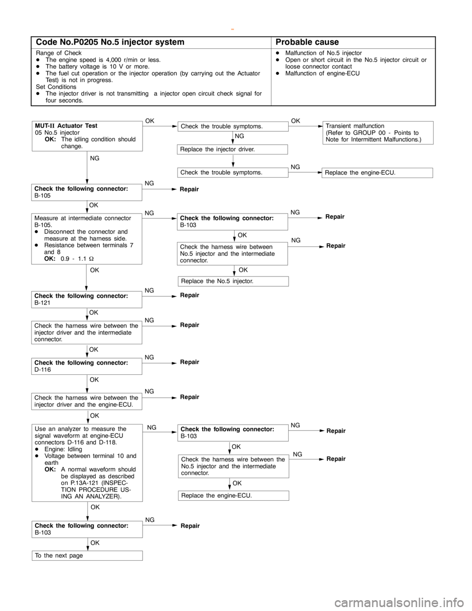
GDI -Troubleshooting
Code No.P0205 No.5 injector systemProbable cause
Range of Check
DThe enginespeed is 4,000 r/min or less.
DThe battery voltage is 10 V or more.
DThe fuel cut operation or the injector operation (by carrying out the Actuator
Test) is not in progress.
Set Conditions
DThe injector driver is not transmitting a injectoropencircuit check signal for
four seconds.DMalfunction of No.5 injector
DOpen or short circuit in the No.5 injector circuit or
loose connector contact
DMalfunction of engine-ECU
NG
Check the following connector:
B-105NG
Repair
OK
NG
Repair
MUT-
IIActuator Test
05 No.5 injector
OK:
The idling condition should
change.OKCheck the trouble symptoms.OKTransient malfunction
(Refer to GROUP 00 - Points to
Note for Intermittent Malfunctions.)
NG
Replace the injector driver.
Check the trouble symptoms.NGReplace the engine-ECU.
OK
Measure at intermediate connector
B-105.
DDisconnect the connector and
measure at the harness side.
DResistance between terminals 7
and 8
OK:
0.9 - 1.1WNGCheck the following connector:
B-103NG
Repair
OK
Replace the No.5 injector.
OK
Check the following connector:
B-121NG
Repair
OK
Check the harness wire between the
injector driver and the intermediate
connector.NG
Repair
OK
Check the following connector:
D-116NG
Repair
OK
Check the harness wire between the
injector driver and the engine-ECU.NG
Repair
OK
Use an analyzer to measure the
signal waveform at engine-ECU
connectors D-116 and D-118.
DEngine: Idling
DVoltage between terminal 10 and
earth
OK:
A normal waveform should
be displayed as described
on P.13A-121 (INSPEC-
TION PROCEDURE US-
ING AN ANALYZER).NGCheck the following connector:
B-103
OK
Check the following connector:
B-103NG
Repair
OK
To the nextpageNG
OK
OK
Check the harness wire between the
No.5 injector and the intermediate
connector.NG
Replace the engine-ECU.
Repair
Repair
Check the harness wire between
No.5 injector and the intermediate
connector.
www.WorkshopManuals.co.uk
Purchased from www.WorkshopManuals.co.uk