key MITSUBISHI MONTERO 2000 Service Repair Manual
[x] Cancel search | Manufacturer: MITSUBISHI, Model Year: 2000, Model line: MONTERO, Model: MITSUBISHI MONTERO 2000Pages: 1839, PDF Size: 29.19 MB
Page 285 of 1839
GDI -Troubleshooting
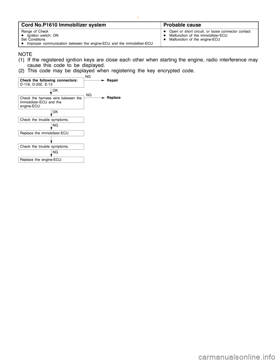
Cord No.P1610 Immobilizer systemProbable cause
Range of Check
DIgnition switch: ON
Set Conditions
DImproper communication between the engine-ECU and the immobilizer-ECUDOpen or short circuit, or loose connector contact
DMalfunction of the immobilizer-ECU
DMalfunction of the engine-ECU
NOTE
(1) If the registered ignition keys are close each other when starting the engine, radio interference may
cause this code to be displayed.
(2) This code may be displayed when registering the key encrypted code.
NG
Replace the engine-ECU.
Check the trouble symptoms.
NG
Replace the immobilizer-ECU
OK
Check the trouble symptoms.
OK
Check the harness wire between the
immobilizer-ECU and the
engine-ECU.NG
Replace
Check the following connectors:
D-118, D-202, E-13NG
Repair
www.WorkshopManuals.co.uk
Purchased from www.WorkshopManuals.co.uk
Page 364 of 1839
Page 513 of 1839
DIESEL FUEL <4M4> -TroubleshootingDIESEL FUEL <4M4> -Troubleshooting13C-22
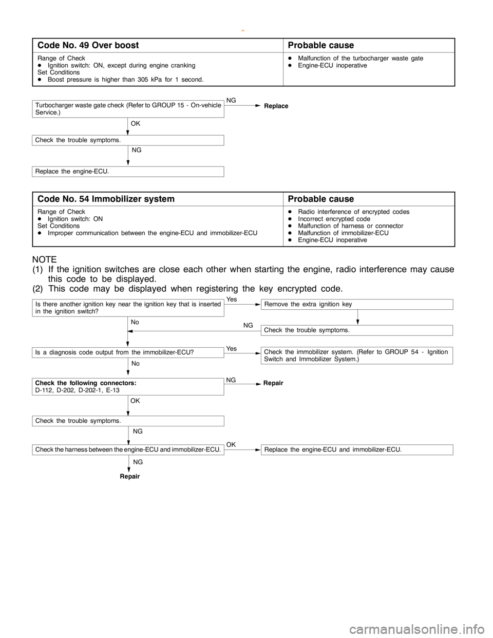
Code No. 49 Over boostProbable cause
Range of Check
DIgnition switch: ON, except duringenginecranking
Set Conditions
DBoost pressure is higher than 305 kPa for 1 second.DMalfunction of the turbocharger waste gate
DEngine-ECU inoperative
Turbocharger waste gate check (Refer to GROUP 15 - On-vehicle
Service.)NG
OK
Check the trouble symptoms.
NG
Replace the engine-ECU.Replace
Code No. 54 Immobilizer systemProbable cause
Range of Check
DIgnition switch: ON
Set Conditions
DImproper communication between the engine-ECU and immobilizer-ECUDRadio interference of encrypted codes
DIncorrect encrypted code
DMalfunction of harness or connector
DMalfunction of immobilizer-ECU
DEngine-ECU inoperative
NOTE
(1) If the ignition switches are close each other when starting the engine, radio interference may cause
this code to be displayed.
(2) This code may be displayed when registering the key encrypted code.
Is there another ignition key near the ignition key that is inserted
in the ignition switch?Ye sRemove the extra ignition key
No
Check the following connectors:
D-112, D-202, D-202-1, E-13NG
Repair
No
Is a diagnosis code output from the immobilizer-ECU?Ye sCheck the immobilizer system. (Refer to GROUP 54 - Ignition
Switch and Immobilizer System.)
NG OK
Check the trouble symptoms.
Check the harness between the engine-ECU and immobilizer-ECU.OKReplace the engine-ECU and immobilizer-ECU.
Check the trouble symptoms. NG
RepairNG
www.WorkshopManuals.co.uk
Purchased from www.WorkshopManuals.co.uk
Page 601 of 1839
MITSUBISHI SC-Troubleshooting13E-12
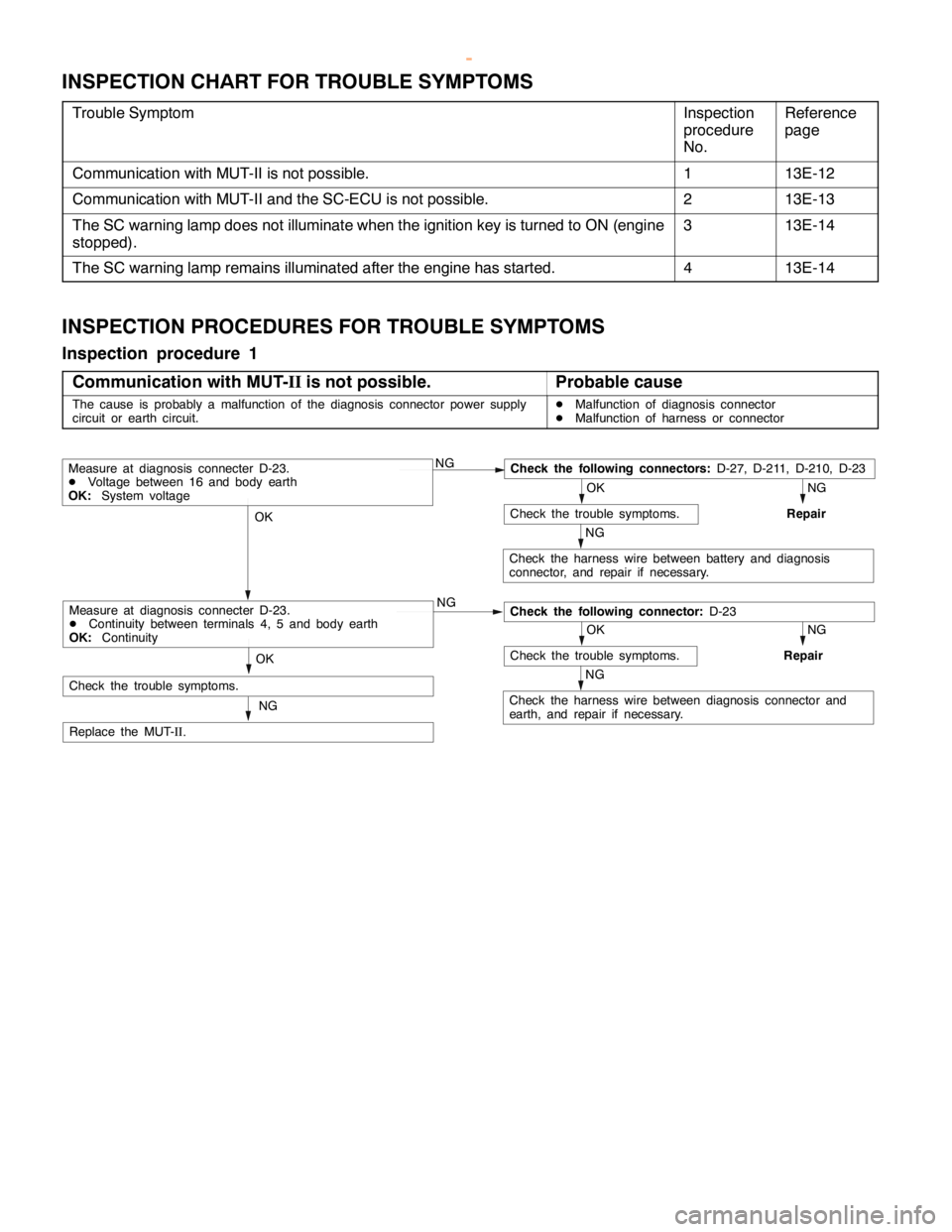
INSPECTION CHART FOR TROUBLE SYMPTOMS
Trouble SymptomInspection
procedure
No.Reference
page
Communication with MUT-II is not possible.113E-12
Communication with MUT-II and the SC-ECU is not possible.213E-13
The SC warning lamp does not illuminate when the ignition key is turned to ON (engine
stopped).313E-14
The SC warning lamp remains illuminated after the engine has started.413E-14
INSPECTION PROCEDURES FOR TROUBLE SYMPTOMS
Inspection procedure 1
Communication with MUT-
IIis not possible.
Probable cause
The cause is probably a malfunction of the diagnosis connector power supply
circuit or earth circuit.DMalfunction of diagnosis connector
DMalfunction of harness or connector
NGCheck the following connectors:
D-27, D-211, D-210, D-23
NG
Repair
OK
Check the trouble symptoms.
NG
Check the harness wire between battery and diagnosis
connector, and repair if necessary.
OK
NG
NG
Repair
OK
Check the trouble symptoms.
NG
Check the harness wire between diagnosis connector and
earth, and repair if necessary.
OK
NG
Replace the MUT-
II.
Measure at diagnosis connecter D-23.
DVoltage between 16 and body earth
OK:
System voltage
Check the following connector:
D-23Measure at diagnosis connecter D-23.
DContinuity between terminals 4, 5 and body earth
OK:
Continuity
Check the trouble symptoms.
www.WorkshopManuals.co.uk
Purchased from www.WorkshopManuals.co.uk
Page 603 of 1839
MITSUBISHI SC-Troubleshooting13E-14
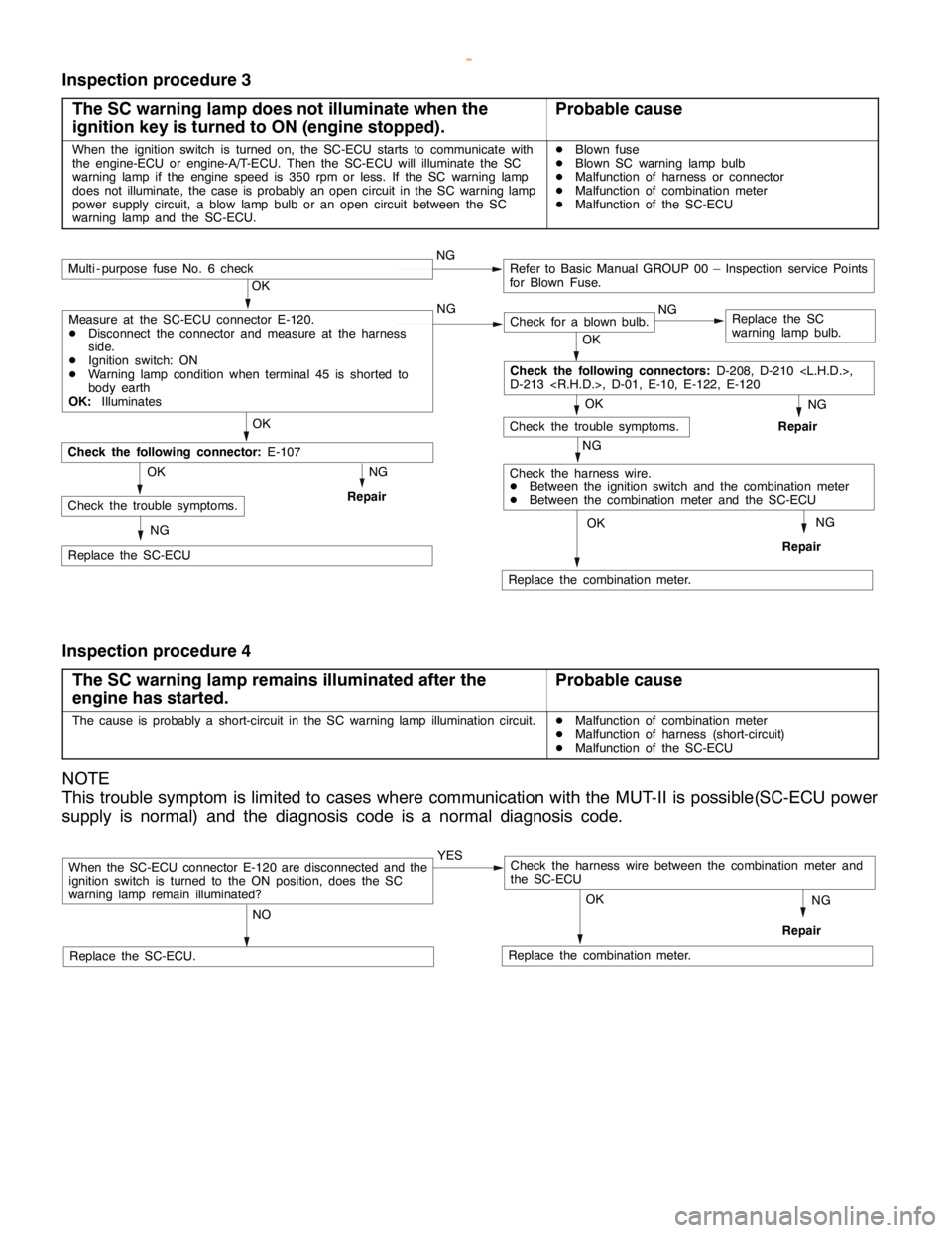
Inspection procedure 3
The SC warning lamp does not illuminate when the
ignition key is turned to ON (engine stopped).
Probable cause
When the ignition switch is turned on, the SC-ECU starts to communicate with
the engine-ECU or engine-A/T-ECU. Then the SC-ECU will illuminate the SC
warning lamp if the engine speed is 350 rpm or less. If the SC warning lamp
does not illuminate, the case is probably an open circuit in the SC warning lamp
power supply circuit, a blow lamp bulb or an open circuit between the SC
warning lamp and the SC-ECU.DBlown fuse
DBlown SC warning lamp bulb
DMalfunction of harness or connector
DMalfunction of combination meter
DMalfunction of the SC-ECU
NG
Replace the combination meter.
NG
Repair
OK
NG
Check for a blown bulb.Replace the SC
warning lamp bulb.
OK
NG
Repair
OK
Check the trouble symptoms.
Multi - purpose fuse No. 6 checkNGRefer to Basic Manual GROUP 00 – Inspection service Points
for Blown Fuse.
NG
Check the harness wire.
DBetween the ignition switch and the combination meter
DBetween the combination meter and the SC-ECU
OK
OK
Replace the SC-ECU
Check the following connector:
E-107
NG
RepairCheck the trouble symptoms.OK
NG
Check the following connectors:
D-208, D-210
D-213
Measure at the SC-ECU connector E-120.
DDisconnect the connector and measure at the harness
side.
DIgnition switch: ON
DWarning lamp condition when terminal 45 is shorted to
body earth
OK:
Illuminates
Inspection procedure 4
The SC warning lamp remains illuminated after the
engine has started.
Probable cause
The cause is probably a short-circuit in the SC warning lamp illumination circuit.DMalfunction of combination meter
DMalfunction of harness (short-circuit)
DMalfunction of the SC-ECU
NOTE
This trouble symptom is limited to cases where communication with the MUT-II is possible(SC-ECU power
supply is normal) and the diagnosis code is a normal diagnosis code.
When the SC-ECU connector E-120 are disconnected and the
ignition switch is turned to the ON position, does the SC
warning lamp remain illuminated?YES
NO
Replace the SC-ECU.Replace the combination meter.
NG
Repair
OK
Check the harness wire between the combination meter and
the SC-ECU
www.WorkshopManuals.co.uk
Purchased from www.WorkshopManuals.co.uk
Page 637 of 1839
DIESEL FUEL <4D5-stepIII>-Troubleshooting13E-27
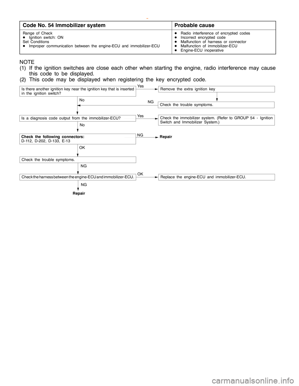
Code No. 54 Immobilizer systemProbable cause
Range of Check
DIgnition switch: ON
Set Conditions
DImproper communication between the engine-ECU and immobilizer-ECUDRadio interference of encrypted codes
DIncorrect encrypted code
DMalfunction of harness or connector
DMalfunction of immobilizer-ECU
DEngine-ECU inoperative
NOTE
(1) If the ignition switches are close each other when starting the engine, radio interference may cause
this code to be displayed.
(2) This code may be displayed when registering the key encrypted code.
Is there another ignition key near the ignition key that is inserted
in the ignition switch?Ye sRemove the extra ignition key
No
Check the following connectors:
D-112, D-202, D-133, E-13NG
Repair
No
Is a diagnosis code output from the immobilizer-ECU?Ye sCheck the immobilizer system. (Refer to GROUP 54 - Ignition
Switch and Immobilizer System.)
NG OK
Check the trouble symptoms.
Check the harness between the engine-ECU and immobilizer-ECU.OKReplace the engine-ECU and immobilizer-ECU.
Check the trouble symptoms. NG
RepairNG
www.WorkshopManuals.co.uk
Purchased from www.WorkshopManuals.co.uk
Page 902 of 1839

Page 993 of 1839

AUTOMATIC TRANSMISSION -
Troubleshooting
TROUBLESHOOTING
DIAGNOSIS FUNCTION
Input signal check procedure
Connect the MUT-II
or a voltage meter to the diagnosis connector, and check the inhibitor switch (reverse)
input signal.
(Refer to GROUP 00 - Guide to Troubleshooting and Inspection Procedures.)
INSPECTION CHART CLASSIFIED BY TROUBLE SYMPTOMS
Trouble SymptomInspection
procedure
No.Reference
page
When the ignition switch is at a position other than the LOCK position, the selector lever
can be moved from the P to the R position even though the brake pedal is not depressed.123-92
When the ignition switch is at a position other than the LOCK position, the selector lever
cannot be moved from the P to the R position even though the brake pedal is being
depressed.223-92
The ignition switch is at the LOCK position, but the selector lever can be moved from the
P to the R position when the brake pedal is depressed.323-93
The selector lever cannot be easily moved from the P to the R position.423-93
The selector lever cannot be moved from the R to the P position.523-93
The ignition key cannot be turned to the LOCK position when the selector lever is at the P
position.623-93
The ignition key can be turned to the LOCK position even when the selector lever is at a
position other than the P position.723-93
INSPECTION PROCEDURES FOR TROUBLE SYMPTOM
Inspection procedure 1
When the ignition switch is at a position other than the
LOCK position, the selector lever can be moved from the
P to the R position even though the brake pedal is not
depressed.
Probable cause
The cause is probably a malfunction of the selector lever assembly lock cam or
of the shift lock cable unit.DMalfunction of lock cam
DMalfunction of shift lock cable unit
Check by referring to the probable causes.
Inspection procedure 2
When the ignition switch is at a position other than the
LOCK position, the selector lever cannot be moved from
the P to the R position even though the brake pedal is
being depressed.
Probable cause
The cause is probably a malfunction of the selector lever assembly, transmission
control cable, shift lock cable unit or the ignition key cylinder lock bar.DMalfunction of selector lever assembly
DMalfunction of transmission control cable
DMalfunction of shift lock cable unit
DMalfunction of lock bar
Check by referring to the probable causes.
www.WorkshopManuals.co.uk
Purchased from www.WorkshopManuals.co.uk
Page 994 of 1839

AUTOMATIC TRANSMISSION -Troubleshooting
Inspection procedure 3
The ignition switch is at the LOCK position, but the
selector lever can be moved from the P to the R position
when the brake pedal is depressed.
Probable cause
The cause is probably a malfunction of the shift lock cable unit or of the ignition
key cylinder lock bar.DMalfunction of shift lock cable unit
DMalfunction of lock bar
Check by referring to the probable causes.
Inspection procedure 4
The selector lever cannot be easily moved from the P to
the R position.
Probable cause
The cause is probably a malfunction of the selector lever assembly, transmission
control cable, shift lock cable unit or the ignition key cylinder lock bar.DMalfunction of selector lever assembly
DMalfunction of transmission control cable
DMalfunction of shift lock cable unit
DMalfunction of lock bar
Check by referring to the probable causes.
Inspection procedure 5
The selector lever cannot be moved from the R to the P
position.
Probable cause
The cause is probably a malfunction of the selector lever assembly or of the
transmission control cable.DMalfunction of selector lever assembly
DMalfunction of transmission control cable
Check by referring to the probable causes.
Inspection procedure 6
The ignition key cannot be turned to the LOCK position
when the selector lever is at the P position.
Probable cause
The cause is probably a malfunction of the selector lever assembly, shift lock
cable unit or the ignition key cylinder lock bar.DMalfunction of selector lever assembly
DMalfunction of shift lock cable unit
DMalfunction of lock bar
Check by referring to the probable causes.
Inspection procedure 7
The ignition key can be turned to the LOCK position even
when the selector lever is at a position other than the P
position.
Probable cause
The cause is probably a malfunction of the shift lock cable unit or of the ignition
key cylinder lock bar.DMalfunction of shift lock cable unit
DMalfunction of lock bar
Check by referring to the probable causes.
www.WorkshopManuals.co.uk
Purchased from www.WorkshopManuals.co.uk
Page 1021 of 1839

S
H IF T LO CK AND KEY IN TE R LO CK MEC HANIS M S
R EM OVA L AND IN STA LLA TIO N
N O TE
W hen re m ovin g and in sta llin g th e tr a nsm is sio n co ntr o l ca ble and sh if t lo ck ca ble unit , be ca re fu l not
t o hit th em again st th e SR S-E C U. V
ie w A
3
2
:T a b posit io n
A
R em oval ste p s
D Fro nt flo or co nso le (R efe r to GRO UP
5 2A .)
D Sw it c h panela nd lo w er co lu m n co ve r
( R efe r to GRO UP 52A -In str u m ent
P anel. )
" AA
1. S hif t lo ck ca ble unit co nnectio n A
A"
2. K ey in te rlo ck ca ble co nnectio n
3 . C ove r
4 . Lock bar
5 . S hif t lo ck ca ble co nnectio n
6 . S hif t lo ck ca ble unit
w
ww.W ork sh opM an uals .c o .u k
P urc h ased f r o m w ww.W ork sh opM an uals .c o .u k