wheel size MITSUBISHI OUTLANDER 2014 3.G Owners Manual
[x] Cancel search | Manufacturer: MITSUBISHI, Model Year: 2014, Model line: OUTLANDER, Model: MITSUBISHI OUTLANDER 2014 3.GPages: 451, PDF Size: 49.08 MB
Page 9 of 451
Outside (Rear) 1-7 Overview
1
N00100602405
Outside (Rear)
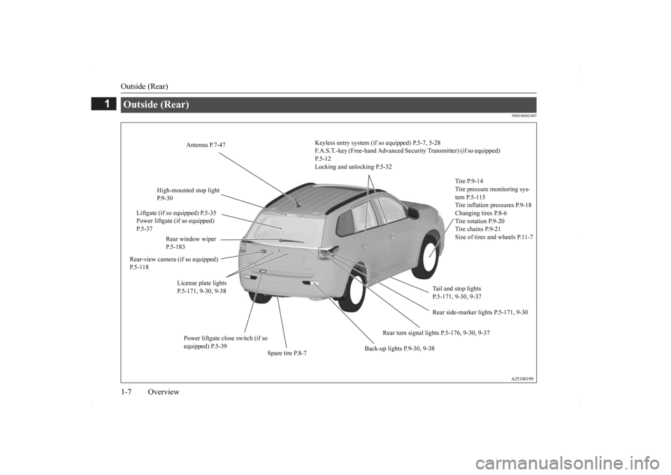
Keyless entry system (if so equipped) P.5-7, 5-28 F.A.S.T.-key (Free-hand Advanced Se
curity Transmitter)
(if so equipped)
P.5-12Locking and unlocking P.5-32
Tire P.9-14 Tire pressure monitoring sys- tem P.5-115Tire inflation pressures P.9-18Changing tires P.8-6 Tire rotation P.9-20 Tire chains P.9-21Size of tires and wheels P.11-7
Tail and stop lights P.5-171, 9-30, 9-37
Rear turn signal lights P.5-176, 9-30, 9-37
Spare tire P.8-7
Back-up lights P.9-30, 9-38
License plate lights P.5-171, 9-30, 9-38
Rear-view camera (if so equipped) P. 5 - 1 1 8
Rear window wiper P.5-183
High-mounted stop light P.9-30
Antenna P.7-47
Liftgate (if so equipped) P.5-35 Power liftgate (if so equipped) P.5-37
Power liftgate close switch (if so equipped) P.5-39
Rear side-marker lights P.5-171, 9-30
BK0200500US.book 7 ページ 2013年2月12日 火曜日 午前9時46分
Page 24 of 451
Modifications to and racing of your vehicle
General information 3-5
3
4. Fueling correctly depends mainly on cor- rect handling of the fuel filler nozzle. Donot tilt the nozzle. Insert the nozzle in the fuel tank filler port as far as it goes. 5. When the nozzle stops automatically, do not add more fuel. 6. To re-install, turn the fuel tank filler pipe cap slowly clockwise
until you hear click-
ing sounds, then gently push the fuel tank filler door closed.
N00301600152
This vehicle should not be modified withnon-Mitsubishi Motors
genuine parts. Mit-
subishi Motors designs and manufactureshigh quality vehicles
with an emphasis on
safety and durability.
Modifications using
non-Mitsubishi Motors genuine parts mayaffect the performance, safety and/or durabil-
ity of your vehicle, a
nd may violate applica-
ble state and/or fe
deral regulations.
DAMAGE OR PERFORMANCE PROB- LEMS RESULTING FROM MODIFICA- TIONS TO OR RACING OF YOUR VEHICLE ARE NOT COVERED UNDERWA R R A N T Y. Examples of modifications to your vehicle that can cause damage or performance prob- lems include the following: Failure to use Mits
ubishi Motors genuine
parts Failure to use required fuel and fluids Failure to use proper
size tires and wheels
Modification of the fu
el, intake, exhaust,
emission, suspension,
engine, drive train
or electrical wiring systems Modification of any onboard com- puter/control module, including repro-gramming, or replac
ing/adding chips to
any onboard computer/control module
Review the Warranty
and Maintenance Man-
ual for further details
regarding warranty cov-
erage.
CAUTION Your vehicle can only be operated using unleaded gasoline. Seri
ous engine and cata-
lytic converter damage will result if leaded gasoline is filled into these vehicles, and consequently, this must
never be attempted.
CAUTIONTo avoid fuel spillage
and overfilling, do not
“top-off” the fuel tank. Spilled fuel could discolor, stain, or cr
ack the vehicle’s paint-
work. If fuel spills on the paintwork, wipe it off with a soft cloth.WA R N I N G Make sure the fuel tank filler cap is securely closed. If the fuel cap were loose, fuel could leak, resulting in a fire.
CAUTION If you need to replace th
e fuel tank filler cap,
use only the cap specified for your modelvehicle.NOTE
If the fuel tank filler cap is not tight while driving, the engine
malfunction indicator
(“SERVICE ENGINE SOON” or “Checkengine light”) may come on when the onboard diagnostic (OBD) system performs a self check.Always tighten the fu
el tank filler cap until
you hear at least 3 clicks. The indicator will go of
f after several driving
cycles. If the indicato
r does not go off, con-
tact your authorized
Mitsubishi Motors
dealer or a repair faci
lity of your choice as
soon as possible.
Modifications to and racing of your vehicle
BK0200500US.book 5 ページ 2013年2月12日 火曜日 午前9時46分
Page 25 of 451
Genuine Mitsubishi Motors parts 3-6 General information
3
N00301701219
The installation of accessories, optional parts, etc., should only be performedwithin the limits prescribed by law, and in accordance with the guidelines and warn- ings contained within the documentsaccompanying this vehicle. Only Mitsubishi Moto
rs approved acces-
sories should be fitt
ed to your vehicle.
Improper installation of
electrical parts
could cause a fire. Refer to the “Modifica- tion/alterations to the electrical or fuelsystems” section with
in this owner’s man-
ual. Using a cellular phone
or radio set inside
the vehicle without an external antenna may cause electrical system interference, which could lead to unsafe vehicle opera-tion. Tires and wheels which do not meet spec- ifications must not be used.Refer to the “Specifi
cations” section for
information regarding wheel and tire sizes.
Due to the large number of accessory and replacement parts provided by different man- ufacturers in the market, it is not always pos-sible for an authorized Mitsubishi Motors dealer to check whether the attachment or installation of a non-Mi
tsubishi Motors genu-
ine parts affects the driving safety of your Mitsubishi-vehicle.
N00301800141
Mitsubishi Motors manufactures high quality vehicles with an emphasis on safety. It isimportant to consult an
authorized Mitsubishi
Motors dealer before installation of any
accessory which may in
volve modification of
the electrical or fuel systems.
N00301400219
Mitsubishi Motors Genuine Parts aredesigned and manufactured to meet high stan- dards of performance, and are recommended for all of your maintenance needs. Also avail-able from your Mitsubishi Motors dealer are a wide variety of acce
ssories to personalize
your new vehicle. Each Mitsubishi Motorsvehicle has a selection of Mitsubishi Motors authorized accessories to choose from to tai- lor your new vehicle to your own personalpreference. Your Mitsubishi Motors dealer’s Parts Manager has information on various audio systems,
protection items,
as well as
interior and exterior ac
cessories available for
your specific model.
Installation of accessories
CAUTION Before any electrical or electronic accesso- ries are installed, cons
ult an authorized Mit-
subishi Motors dealer.
WA R N I N G While driving, do not use a cellular phone in a way that hinder
s safe driving. Any-
thing, including cell
ular phone usage, that
distracts you from the safe operation of your vehicle incr
eases your risk of an acci-
dent.Refer to and follow al
l state and local laws
in your area regardi
ng cellular phone
usage while driving.
Important point! Modification/alterations to the electrical or fuel systems
CAUTION Please consult an authorized Mitsubishi Motors dealer concer
ning any such acces-
sory fitment or modification. If the wires interfere
with the vehicle body or
improper installation me
thods are used (pro-
tective fuses not included, etc.), electronic devices may be adversel
y affected, resulting
in a fire, vehicle dama
ge, or other accident.
Genuine Mitsubishi Motors parts
BK0200500US.book 6 ページ 2013年2月12日 火曜日 午前9時46分
Page 158 of 451
S-AWC (Super-All Wheel Control) (if so equipped) 5-80 Features and controls
5
Warning display Warning display
N00542501058
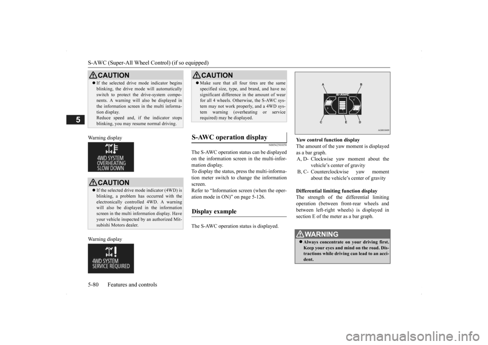
The S-AWC operation status can be displayed on the information screen in the multi-infor- mation display. To display the status, press the multi-informa-tion meter switch to change the information screen. Refer to “Information screen (when the oper-ation mode in ON)” on page 5-126. The S-AWC operation status is displayed.
CAUTION If the selected drive mode indicator begins blinking, the drive m
ode will automatically
switch to protect the drive-system compo-nents. A warning will
also be displayed in
the information screen in the multi informa- tion display.Reduce speed and, if the indicator stops blinking, you may resume normal driving.CAUTION If the selected drive mode indicator (4WD) is blinking, a problem has occurred with theelectronically controll
ed 4WD. A warning
will also be displayed in the information screen in the multi information display. Haveyour vehicle inspected by an authorized Mit- subishi Motors dealer.
CAUTION Make sure that all four tires are the same specified size, type, a
nd brand, and have no
significant difference in the amount of wearfor all 4 wheels. Otherwise, the S-AWC sys- tem may not work properly, and a 4WD sys- tem warning (overh
eating or service
required) may
be displayed.
S-AWC operation display
Display example
Yaw control function display The amount of the yaw moment is displayed as a bar graph. A, D- Clockwise yaw moment about the
vehicle’s center of gravity
B, C- Counterclockwise yaw moment
about the vehicle’s
center of gravity
Differential limiting
function display
The strength of the differential limitingoperation (between front-rear wheels and between left-right whee
ls) is displayed in
section E of the me
ter as a bar graph.
WA R N I N GAlways concentrate on
your driving first.
Keep your eyes and mi
nd on the road. Dis-
tractions while driving
can lead to an acci-
dent.
BK0200500US.book 80 ページ 2013年2月12日 火曜日 午前9時46分
Page 162 of 451
Service brake 5-84 Features and controls
5
vehicle when operating in 4-wheel drive is greatly affected by the condition of the tires. Pay close attention to the tires. Install only the specified tires on all wheels. Refer to “Tires and wheels” on page 11-7. Be sure all four tires and wheels are the same size and type. When it is necessary to replace any of the tires or wheels, replace all four. All tires should be ro
tated before the wear
difference between the front and rear tiresis recognizable.
Good vehicle performance cannot be expected if there is a difference in wear between tires. Refer to “Tire rotation” onpage 9-20. Check the tire inflation pressure regularly.
N00517500275
Overuse of the brake can cause weakening, resulting in poor brake response and prema- ture wear of the brake pads. When driving down a long or steep hill, useengine braking by downshifting.
CAUTION Always use tires of th
e same size, type, and
brand that have no wear differences. Using tires of different size, type, brands or degree of wear, will increase the differential oil tem-perature and result in possible damage to the driving system. Further, the drive train will be subject to excessi
ve loading, possibly
leading to oil leakage,
component seizure, or
other serious failures.
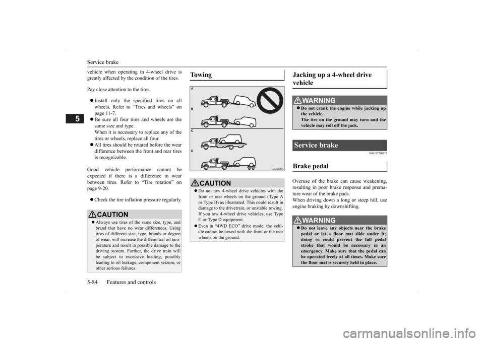
To w i n g
CAUTION Do not tow 4-wheel drive vehicles with the front or rear wheels on the ground (Type A or Type B) as illustrated. This could result in damage to the drivetra
in, or unstable towing.
If you tow 4-wheel drive vehicles, use TypeC or Type D equipment. Even in “4WD ECO” drive mode, the vehi- cle cannot be towed with the front or the rear wheels on the ground.
Jacking up a 4-wheel drive vehicle
WA R N I N G Do not crank the engine while jacking up the vehicle. The tire on the ground may turn and thevehicle may roll off the jack.
Service brake Brake pedal
WA R N I N G Do not leave any obje
cts near the brake
pedal or let a floor
mat slide under it;
doing so could prevent the full pedal stroke that would be necessary in an emergency. Make sure that the pedal canbe operated freely at
all times. Make sure
the floor mat is securely held in place.
BK0200500US.book 84 ページ 2013年2月12日 火曜日 午前9時46分
Page 165 of 451
Anti-lock braking system
Features and controls 5-87
5
N00517900240
The anti-lock braking
system helps prevent
the wheels from locking up when braking. This helps maintain vehicle drivability andsteering wheel handling.
When using the anti-lock brakes (sudden braking), steering is slightly different from normal driving conditions. Use the steering wheel carefully. Always keep a safe distance from the vehicle in front of you. Even if your vehi- cle is equipped with
the anti-lock braking
system, leave a greater braking distance when: • Driving on gravel or snow-covered roads. • Driving on uneven road surfaces. Operation of anti-lock braking system is not restricted
situations where brakes are
applied suddenly. This system may alsoprevent the wheels from locking when you drive over manholes, steel roadwork plates, road markings
, or any uneven road
surface. When the anti-lock braking system is in use, you may feel the brake pedal vibrat-ing and hear a unique
sound. It may also
feel as if the pedal
resists being pressed.
In this situation, simply hold the brakepedal down firmly. Do not pump the brake, which will result in reduced braking performance.
N00531601684
Warning light Warning display
When the brake assist system is in use while driving, you may feel as if the depressedbrake pedal is soft, the pedal moves in smallmotions in conjunction with the operation noise, or the vehicle body and the steering wheel vibrate. This occurs when the brakeassist system is ope
rating normally and does
not indicate faulty
operation. Continue to
depress the brake pedal. You may hear an operation noise when the brake pedal is suddenl
y or fully depressed
while stationary. This does not indicate a malfunction and the brake assist system is operating normally. When the anti-lock brake system warning light or only active st
ability control warning
light illuminate, the brake assist system in not functioning.
Anti-lock braking system
NOTE
Driving hints
CAUTION The anti-lock braking system cannot prevent accidents. It is your
responsibility to take
safety precautions a
nd to drive carefully.
To prevent failure of the anti-lock braking system, be sure all 4 wheels and tires are thesame size and the same type.NOTE
A whining sound is emitted from the engine compartment when driving immediately after starting the engine. These are the nor-mal sounds the anti-lock braking system makes when performing a self-check. It does not indicate
a malfunction.
The anti-lock braking system can be used after the vehicle has
reached a speed over
approximately 6 mph (10 km/h). It stops working when the vehicle slows below 3 mph (5 km/h).
Anti-lock braking system warn- ing light / display
BK0200500US.book 87 ページ 2013年2月12日 火曜日 午前9時46分
Page 168 of 451
Active stability control (ASC) 5-90 Features and controls
5
If there is a malfunction in the system, the warning light will come on and the warningdisplay will appear on the information screen in the multi information display. Under normal conditions, the warning lightcome on when the ignition switch is turned to the “ON” position or the operation mode is put in ON, and goes off after the engine hasstarted.
N00559100147
The Active stability
control (ASC) takes
overall control of the
anti-lock braking sys-
tem, traction control function and skid control function to help maintain the vehicle’s controland traction. Please read
this section in con-
junction with the page on the anti-lock brak- ing system, traction control function and skidcontrol function. Anti-lock braking system
P.5-87
Traction control function
P.5-90
Skid control function
P.5-90
N00559200021
On slippery surfaces, the traction control function prevents the drive wheels from spin- ning excessive, thus helping the vehicle tostart moving from a stopp
ed condition.
It also
provides sufficient driv
ing force and steering
performance as the vehicle turns while press-ing the acceleration pedal.
N00559300019
The skid control function is designed to helpthe driver maintain control of the vehicle on slippery roads or during rapid steering
CAUTION If the warning display appears while the engine is running, have
the vehicle inspected
by an authorized Mitsubishi Motors dealer or a repair facility of
your choice as soon as
possible. It may become harder to turn thesteering wheel.
Active stability control (ASC)
CAUTION Do not over-rely on the ASC. Even the ASC cannot prevent the natural laws of physics from acting on the vehicle. This system, like any other system, has
limits and cannot help
you to maintain traction and control of the vehicle in all circumstances. Reckless driv- ing can lead to accident
s. It is the driver’s
responsibillty to drive carefully, This means taking into account the traffic, road and envi- ronmental conditions. Be sure to use the same specified type and size of tire on all four
wheels. Otherwise, the
ASC may not work properly. Do not install any aftermarket limited slip differential (LSD) on your vehicle. The ASC may stop functioning properly.NOTE
An operation noise may be emitted from the engine compartment in the following situa-tions. The sound is associated with checkingthe operations of the ASC. At this time, you may feel a shock from the brake pedal if you depress it. These do not
indicate a malfunc-
tion. • When the ignition switch is set to the “ON” position. • When the vehicle is driven for a while after the engine is turned on.
When the ASC is acti
vated, you may feel a
vibration in the vehicl
e body or hear a whin-
ing sound from the engine compartment.This indicates that th
e system is operating
normally. It does not i
ndicate a malfunction.
When the anti-lock braking system warning light is illuminated, the ASC is not active.
Traction control function
CAUTION When driving a vehicle on a snowy or icy road, be sure to install snow tires and drive the vehicle at moderate speeds.
Skid control function
NOTE
BK0200500US.book 90 ページ 2013年2月12日 火曜日 午前9時46分
Page 194 of 451

Tire pressure monitoring system 5-116 Features and controls
5
Each tire, including the spare (if provided), should be checked monthly when cold andinflated to the inflation pressure recom- mended by the vehicle manufacturer on the vehicle placard or tire
inflation pressure label.
(If your vehicle has tires of a different size than the size indicated on the vehicle placard or tire inflation pressure label, you shoulddetermine the proper ti
re inflation pressure
for those tires.) As an added safety feature, your vehicle hasbeen equipped with a tire pressure monitoring system (TPMS) that illuminates a low tire pressure telltale when
one or more of your
tires is significant
ly under-inflated.
Accordingly, when the low tire pressure tell-tale illuminates, you should stop and check your tires as soon as possible, and inflate them to the proper pressure. Driving on a sig-nificantly under-inflated
tire causes the tire to
overheat and can lead
to tire failure.
Under-inflation also reduces fuel efficiency and tire tread life, and may affect the vehi-cle’s handling and stoppi
ng ability. Please
note that the TPMS is
not a substitute for
proper tire maintenance,
and it is the driver’s
responsibility to
maintain corre
ct tire pres-
sure, even if under-inflation has not reached the level to trigger illumination of the TPMSlow tire pressure telltale. Your vehicle has also
been equipped with a
TPMS malfunction indica
tor to indicate when
the system is not operating properly. The TPMS malfunction indicator is combined with the low tire pressure telltale.When the system detects a malfunction, the telltale will flash for approximately one min- ute and then remain c
ontinuously illuminated.
This sequence will c
ontinue upon subsequent
vehicle start-ups as long as the malfunction exists.When the malfunction indicator is illumi- nated, the system may not
be able to detect or
signal low tire pr
essure as intended.
TPMS malfunctions may
occur for a variety
of reasons, including the installation of replacement or alternate tires or wheels on thevehicle that prevent the TPMS from function- ing properly. Always
check the TPMS mal-
function telltale after replacing one or moretires or wheels on your vehicle to ensure that the replacement or alternate tires and wheels
allow the TPMS to continue to function prop- erly.
N00532801511
1. If the tire pressure monitoring systemwarning light illuminates, avoiding hard braking, sharp steering maneuvers and high speeds. You should stop and adjust the tires to the proper inflation pressure as soon as possible. Adjust the spare tire atthe same time. Refer to “Tires” on page 9-14.
NOTE
In addition, the warni
ng display is displayed
on the information screen in the multi-infor-mation display.
If the warning light / display illuminates while driving
NOTE
In addition, the warni
ng display is displayed
on the information screen in the multi-infor- mation display. When inspecting or adjusting the tire pres- sure, do not apply excessive force to the valve stem to
avoid breakage.
After inspecting or adjusting the tire pres- sure, always reinstall the valve cap on thevalve stem. Without the valve cap, di
rt or moisture could
get into the valve, resulting in damage to thetire inflation pressure sensor. Do not use metal valve caps, which may cause a metal reaction,
resulting in corrosion
and damage of the tire
inflation pressure sen-
sors.
BK0200500US.book 116 ページ 2013年2月12日 火曜日 午前9時46分
Page 262 of 451
Electric rear window defogger switch 5-184 Features and controls
5
N00523701413
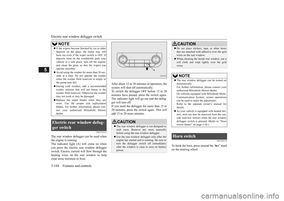
The rear window defogger can be used when the engine is running. The indicator light (A) will come on whenyou press the electric rear window defogger switch. Electric current will flow through the heating wires on the rear window to helpclear away moisture or frost.
After about 15 to 20 minutes of operation, the system will shut off automatically.To switch the defogger OFF before 15 to 20 minutes have passed, pr
ess the switch again.
The indicator light will go out and the defog-ger will turn off. If you need the defogger for more than 15 to 20 minutes, press the switch again. This willadd 15 to 20 more minutes.
N00523801195
To honk the horn, press around the “ ” markon the steering wheel.
If the wipers become bl
ocked by ice or other
deposits on the glass, the motor may stillburn out even if the wiper switch is OFF. Ifdeposits form on the windshield, park your vehicle in a safe place, turn off the engine, and clean the glass so that the wipers canoperate smoothly. Avoid using the washer for more than 20 sec- onds at a time. Do not
operate the washer
when the washer fluid reservoir is empty or the pump may fail. During cold weather, add a recommended washer solution that will not freeze in thewasher fluid reservoir. Otherwise the washer may not work or may be damaged. Replace the wiper blades when they are worn. Use the proper size replacement blades. For further info
rmation, please con-
tact your authorized
Mitsubishi Motors
dealer.
Electric rear window defog- ger switch
NOTE
CAUTION The rear window defogge
r is not designed to
melt snow. Remove
any snow manually
before using the rear window defogger. Use the rear window de
fogger only after the
engine has started and
is running. Be sure to
turn the defogger switch off immediatelyafter the window is cl
ear to save on battery
power.
Do not place stickers
, tape, or other items
that are attached with
adhesive over the grid
wires on the rear window. When cleaning the insi
de rear window, use a
soft cloth and wipe
lightly over the grid
wires.NOTE
The rear window defogger can be turned on automatically. For further information, please contact your authorized Mitsubishi Motors dealer.On vehicles e
quipped with Mitsubishi Multi-
Communication System, screen operations can be used to ma
ke the adjustment.
Refer to the separate
owner’s manual for
details. As your vehicle is equi
pped with heated mir-
rors, mist can also be removed from the out- side rearview mirrors
when the rear window
defogger switch is pre
ssed. (Refer to “Door
mirror heater” on page 5-56.)
Horn switch
CAUTION
BK0200500US.book 184 ページ 2013年2月12日 火曜日 午前9時46分
Page 378 of 451
How to change a tire 8-12 For emergencies
8
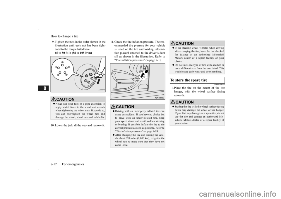
9. Tighten the nuts in the order shown in the illustration until each
nut has been tight-
ened to the torque listed here. 65 to 80 ft-lb (88 to 108 N•m)
10. Lower the jack all th
e way and remove it.
11. Check the tire inflation pressure. The rec-
ommended tire pressure for your vehicleis listed on the tire and loading informa- tion placard attached to the driver’s door sill as shown in the illustration. Refer to“Tire inflation pressures” on page 9-18.
N00832300020
1. Place the tire on the center of the tirehanger, with the wheel surface facing upwards.
CAUTION Never use your foot or a pipe extension to apply added force to the wheel nut wrench when tightening the wheel nuts. If you do so,you can over-tighten the wheel nuts and damage the wheel, wheel nuts and hub bolts.
CAUTION Driving with an improperly inflated tire can cause an accident. If
you have no choice but
to drive with an under-inflated tire, keep your speed down and avoid sudden steering or braking, if possible. Inflate the tire to thecorrect pressure as s
oon as possible. Refer to
“Tire inflation pressures” on page 9-18. After changing the tire
and driving the vehi-
cle about 620 miles (1,000 km), retighten the wheel nuts to make sure that they have notcome loose.
If the steering wheel vibrates when driving after changing th
e tire, have the tire checked
for balance at an authorized MitsubishiMotors dealer or a repair facility of your choice. Do not mix one type of
tire with another or
use a different size from the one listed. This would cause early we
ar and poor handling.
To store the spare tire
CAUTIONStoring the tire with the wheel surface facing down may damage the wheel or tire hanger. If you find any damage
on a spare tire, do not
use the tire and contact an authorized Mit-subishi Motors dealer or a repair facility of your choice.CAUTION
BK0200500US.book 12 ページ 2013年2月12日 火曜日 午前9時46分